

Page 1
INSTRUCCIONES DE INSTALACIÓN
NAPDH11L
NAPDH11
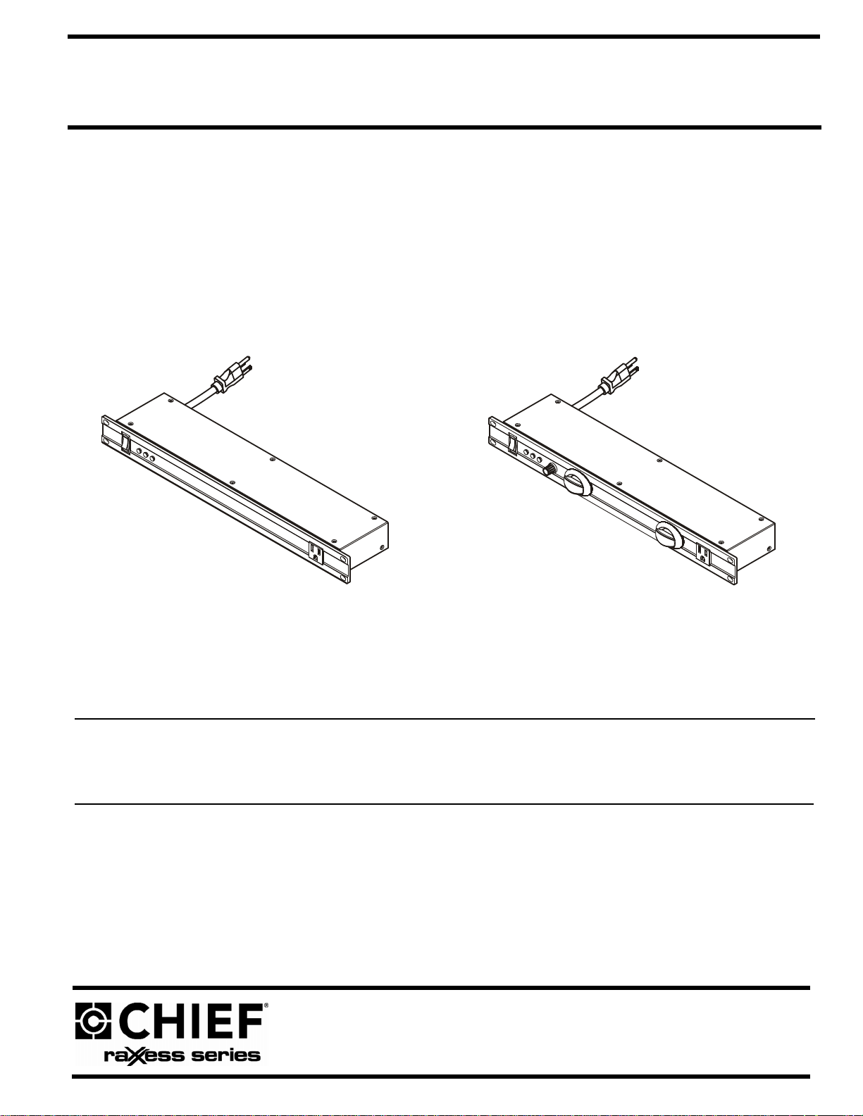
Surge Arresters
Descargadores de sobretensión
NAPDH11/NAPDH11L
INSTALLATION INSTRUCTIONS
INSTRUCCIONES DE INSTALACIÓN
Page 2
NAPDH11/NAPDH11L Installation Instructions
DISCLAIMER
Milestone AV Technologies and its affiliated corporations and
subsidiaries (collectively "Milestone"), intend to make this
manual accurate and complete. However, Milestone makes no
claim that the information contained herein covers all details,
conditions or variations, nor does it provide for every possible
contingency in connection with the installation or use of this
product. The information contained in this document is subject
to change without notice or obligation of any kind. Milestone
makes no representation of warranty, expressed or implied,
regarding the information contained herein. Milestone assumes
no responsibility for accuracy, completeness or sufficiency of
the information contained in this document.
Chief® is a registered trademark of Milestone AV T echnologies.
All rights reserved.
IMPORTANT SAFETY INSTRUCTIONS
WARNING alerts you to the possibility of
serious injury or death if you do not follow the instructions.
CAUTION
damage or destruction of equipment if you do not follow the
corresponding instructions.
WARNING
FOLLOW THE FOLLOWING INSTRUCTIONS CAN RESULT
IN SERIOUS PERSONAL INJURY, DAMAGE TO EQUIPMENT
OR VOIDING OF FACTORY WARRANTY. It is the installer’s
responsibility to make sure all components are properly
assembled and installed using the instructions provided.
alerts you to the possibility of
:
FAILURE TO READ AND
4. Do not install this device if there is not at least 10 meters
(30 ft) or more of wire between the electrical outlet and the
electrical service panel.
5. The input plug of this power tap is intended to serve as the
disconnect device, it shall be easily accessible and
withdrawn.
6. This surge arrester does not contain internal Circuit Breaker
protection; INSTALLER MUST ensure that the input of this
surge arrester is connected individually to an electrical
service panel that is protect ed with a UL Listed 20A
(Minimum) Circuit Breaker for overload protection of the
surge arrester.
7. All doors and accessories must be grounded.
CAUTION Avoid potential personal injuries
and property damage!
1. Elevated Operating Ambient - If installed in a closed or
multi-unit rack assembly, the operating ambient
temperature of the rack environment may be greater than
room ambient. Therefore, consideration should be given to
installing the equipment in an environment compatible with
the maximum ambient temperature (0-40°C/32-104°F)
specified by the manufacturer.
2. Reduced Air Flow - Installation of the equipment in a rack
should be such that the amount of air flow required for safe
operation of the equipment is not compromised.
3. Circuit Overloading - Consideration should be given to the
connection of the equipment to the supply circuit and the
effect that overloading of the circuits might have on
overcurrent protection and supply wiring. Appropriate
consideration of equipment nameplate ratings should be
used when addressing this concern.
4. Reliable Earthing - Reliable earthing of rack-mounted
equipment should be maintained. Particular attention
should be given to supply connections other than direct
connections to the branch circuit (e.g. use of power strips).
NOTE:
This system has no user serviceable parts.
--SAVE THESE INSTRUCTIONS--
READ ALL INSTRUCTIONS BEFORE USING THIS
PRODUCT!!!!
DANGER: TO REDUCE THE RISK OF
ELECTRIC SHOCK:
1. Use only in dry locations indoors.
2. Do not plug into another relocatable power tap.
3. This device features an internal protection that will
disconnect the surge protective component at the end of its
useful life but will maintain power to the load - now
unprotected. If this situation is undesirable for the
application, follow the manufacturer’s instructions for
replacing the device.
2
Page 3
Installation Instructions NAPDH11/NAPDH11L
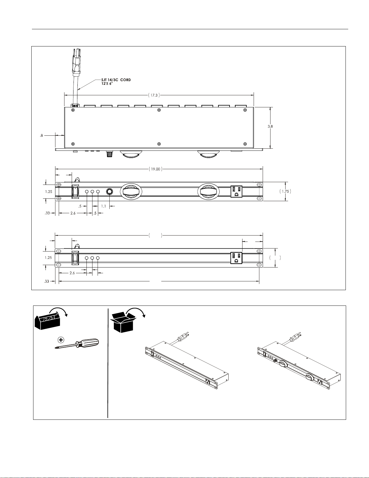
19.00
1.75
1.5
1.9
.5
.5
18.34
2X
2X
1.5
NAPDH11
NAPDH11L
A (1)
[Surge arrester]
Hardware required,
(4) 10-32 x 3/4" screws
not included:
OR
Cable tie(s)
DIMENSIONS
TOOLS / HARDWARE / PARTS
3
Page 4
NAPDH11/NAPDH11L Installation Instructions
1
2
3
4
5
4
5
6
NAPDH11L
NAPDH11
(back view)
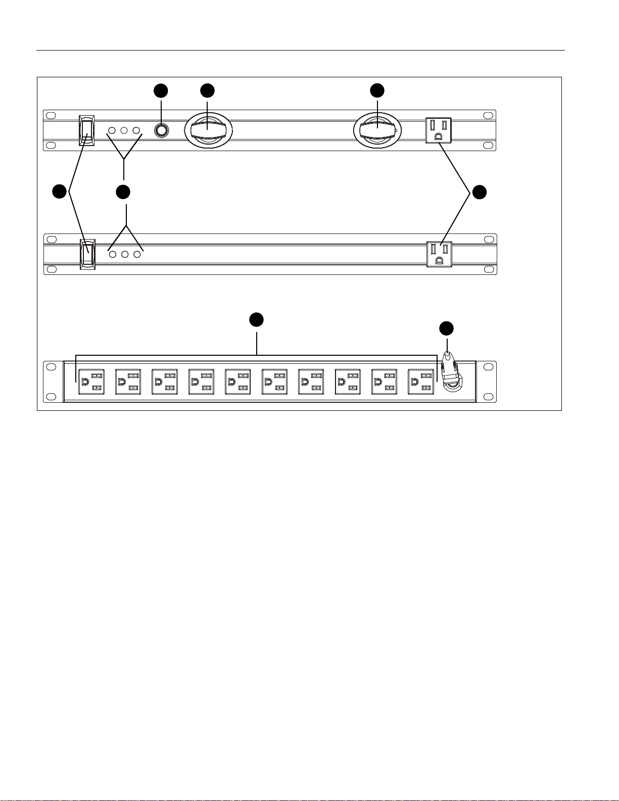
NAPDH11/NAPDH11L FEATURES
FEATURES
1. Reset/Off Switch: Resettable fuse and power off switch.
2. LED Indicators (POWER / PROTECTED / GROUNDED:
Indicators illuminate to indicate that the surge arrester is
working. If the lights FAIL to illuminate see the LED
Indicators section.
3. Dimmer: Controls brightness of pull-out lights.
4. Pull-Out Lights: Pull out and rotate to direct light as
needed.
5. Protected Outlets: 11 x NEMA-15R receptacles, 10 outlets
on back, 1 outlet on front.
6. Power Input Connection: NEMA5-15P plug (5-15P
straight plug)
SPECIFICATIONS
Clamping Response Time: <1ns
UL Electrical Rating: 12A Max/125Vac/60Hz/1500W
Voltage Protection Rating: 400V(L-N) 400V(L-G) 400V(N-G)
EMI/RFI Noise Filtration: 30dB (100KHz - 1 MHz)
Joule Rating: 2,400 Joules
Power Input Connection: NEMA5-15P plug (5-15P straight plug)
Protected Outlets: 11 x NEMA-15R Receptacles
LED Indicators: Power (yellow)/Protected (red )/Grounded (gre en)
Dimmable Pull Out Rack Lights
4
Page 5

Installation Instructions NAPDH11/NAPDH11L
1
x 4
(A)
(NAPDH11L shown in NE1F2023 rack
-- back view)
INSTALLATION
The NAPDH11/NAPDH1 1L surge arresters are designed for use
with 19" wide equipment racks. See the specific installation
instructions provided with the rack for additional installation
information.
1. Attach the surge arrester (A) within the rack, using four
10-32 x 3/4" screws (not included). (See Figure 1)
LED INDICATORS
The
POWER / PROTECTED / GROUNDED
under normal working conditions.
IMPORTANT ! : If any of the lights fail to illuminate after
going through the following steps, replace the surge
arrester.
Power (Yellow)
1. If the
2. If the
3. If the
Power
plugged into a working outlet and that the RESET / OFF
switch is not in the OFF position.
surge protected outlets and press RESET on the RESET /
OFF switch.
replaced.
light is off, verify that the surge arrester is
Power
light is still off, unplug all accessories from the
Power
light remains off, the surge arrester should be
Protected (Red)
1. If the
Protected
lights are on, the surge arrester should be replaced.
light is off but the
Grounded (Green)
1. If the
2. If the
Grounded
lights are on, verify that you are using a properly grounded
outlet.
Grounded
replaced.
light is off but the
light is still off, the surge arrester should be
lights illuminate
Power
and
Power
and
Grounded
Protected
Figure 1
5
Page 6

NAPDH11/NAPDH11L Installation Instructions
6
Page 7

INSTRUCCIONES DE INSTALACIÓN
NAPDH11L
NAPDH11
Descargadores de sobretensión
NAPDH11/NAPDH11L
INSTRUCCIONES DE INSTALACIÓN
Page 8

NAPDH11/NAPDH11L Installation Instructions
DESCARGO DE RESPONSABILIDAD
Milestone AV Technologies y sus filiales y compañías asociadas
(conjuntamente, "Milestone") procuran que este manual sea
preciso y esté completo. No obstante, Milestone no garantiza que
la información aquí incluida proporcione todos los detalles, las
condiciones o las variaciones existentes, ni contemple todas las
posibles contingencias relacionadas con la instalación o el uso
de este producto. La información brindada en este manual
puede sufrir modificaciones sin previo aviso, sin que ello genere
obligaciones de ningún tipo. Milestone no otorga garantía alguna,
ni expresa ni implícita, respecto de la información aquí incluida.
Milestone no se responsabiliza de que la información contenida en
este documento sea precisa o suficiente, ni de que esté completa.
Chief® es una marca comercial registrada de Milestone AV
Technologies. Reservados todos los derechos.
INSTRUCCIONES DE SEGURIDAD
IMPORTANTES
ADVERTENCIA:
la posibilidad de sufrir lesiones graves o incluso la muerte si no
sigue las instrucciones.
PRECAUCIÓN:
posibilidad de que el equipo se dañe o resulte destruido si no
sigue las instrucciones.
ADVERTENCIA:
LAS INSTRUCCIONES QUE SIGUEN PUEDE CAUSAR
LESIONES GRAVES, OCASIONAR DAÑOS AL EQUIPO
O DEJAR SIN EFECTO LA GARANTÍA DEL F ABRICANTE.
Es responsabilidad del instalador asegurarse de que todos los
componentes estén correctamente ensamblados e instalados
de acuerdo con las instrucciones proporcionadas.
Alerta al usuario sobre
Alerta al usuario sobre la
NO LEER Y RESPET AR
4. No instale este dispositivo si no hay al menos 10 metros
(30 pies) o más de cable entre el tomacorriente y el
tablero eléctrico.
5. El enchufe de este tomacorriente múltiple constituye su
mecanismo de desconexión, por lo cual deberá ubicarse en
un lugar al que pueda accederse fácilmente para retirarlo.
6. Este descargador de sobretensión no cuenta con un
interruptor automático para protección interna, por lo cual
el INSTALADOR DEBE cerciorar que el enchufe de este
descargador de sobretensión se conecte individualmente a
un tablero eléctrico protegido por un interruptor automático
de 20A (como mínimo) y aceptado por UL a fin de proveer
protección contra sobrecargas para el descargador de
sobretensión.
7. Todas las puertas y todos los accesorios deben estar
conectados a tierra.
PRECAUCIÓN:
materiales.
1. Temperatura de funcionamiento eleva da – Si se lo instala en
un bastidor cerrado o con múltiples unidades, la temperatura
ambiente en funcionamiento puede ser mayor a la temperatura
de la habitación. Por lo ta nto, debe tenerse en consideración
que el equipo se debe instalar en una habitación comp atible
con la temperatura ambiente máxima (0-40°C/32-104°F) que
especifica el fabricante.
2. Flujo de aire reducido – La instalación del equipo en un
bastidor debe realizarse respetando el monto de flujo de
aire requerido para el manejo seguro del equipo.
3. Sobrecarga del circuito – La conexión del equipo al circuito
de alimentación debe realizarse teniendo en consideración
el efecto que podría ocasionar la sobrecarga de los circuitos
sobre la protección contra sobretensión y el cableado
eléctrico. Por lo tanto, deben tenerse en cuenta los valores
indicados en la placa de identificación del equipo.
4. Conexión a tierra confiable – Los equipos instalados en un
bastidor siempre deben contar con una conexión a tierra
confiable. Se debe prestar especial atención a todas las
conexiones eléctricas que no son conexiones directas al circuito
derivado (por ej. cuando se usan tomacorrientes múltiples).
NOTA:
Esta unidad no contiene piezas que el usuario
pueda reparar.
Evite lesiones y daños
LEA TODAS LAS INSTRUCCIONES ANTES DE UTILIZAR
ESTE PRODUCTO.
PELIGRO:
DESCARGA ELÉCTRICA:
1. Utilice este producto únicamente en lugares techados y secos.
2. No lo conecte a otro tomacorriente múltiple móvil.
3. Este dispositivo cuenta con un sistema de protección interna
que desconectará el componente de protección contra
sobretensión cuando finalice su vida útil pero seguirá
suministrando corriente, aunque sin protección. Si esta
situación no es conveniente para la aplicación, siga las
instrucciones del fabricante para reemplazar el dispositivo.
PARA REDUCIR EL RIESGO DE
8
CONSERVE ESTE MANUAL
DE INSTRUCCIONES
Page 9

Installation Instructions NAPDH11/NAPDH11L
19.00
1.75
1.5
1.9
.5
.5
18.34
2X
2X
1.5
NAPDH11
NAPDH11L
A (1)
[Descargador
Elementos requeridos,
(4) tornillos 10-32 x 3/4"
no incluidos:
O
de sobretensión]
Sujetacable(s)
DIMENSIONES
HERRAMIENTAS / ELEMENTOS / PIEZAS
9
Page 10

NAPDH11/NAPDH11L Installation Instructions
1
2
3
4
5
4
5
6
NAPDH11L
NAPDH11
(vista
posterior)
CARACTERÍSTICAS DE NAPDH11/NAPDH11L
CARACTERÍSTICAS
1.
Interruptor Reset/Off:
y apagado.
2.
Indicadores luminosos LED (POW ER / PROTECTED /
GROUNDED):
de sobretensión está funcionando. Si las luces NO encienden
consulte la sección
3.
Atenuador:
4.
Luces extraíbles:
sea necesario.
T omacorrientes protegidos:
5.
10 en la parte posterior y 1 en la parte frontal.
6.
Conector de alimentación:
(enchufe plano 5-15P)
controla el brillo de las luces extraíbles.
interruptor de fusible restaurable
los indicadores se iluminan si el descargador
Indicadores LED
extraiga y rote para dirigir la luz según
.
1 1 tomacorrientes NEMA-15R:
enchufe NEMA 5-15P
ESPECIFICACIONES
Tiempo de respuesta de sujeción: <1 ns
Valores eléctricos de UL: 12A Máx / 125V/CA / 60Hz / 1500W
Capacidad de protección contra sobretensión: 400 V (L-N),
400 V (L-G), 400 V (N-G)
Filtración de ruido EMI/RFI: 30dB (100KHz - 1 MHz)
Joules: 2400
Conector de alimentación: enchufe NEMA 5-15 P (en chufe
plano 5-15P)
Tomacorrientes protegidos: 11 tomacorrientes NEMA-15R
Indicadores luminosos LED: Power (amarillo) / Protected (rojo) /
Grounded (verde)
Luces extraíbles y regulables para bastidor
10
Page 11

Installation Instructions NAPDH11/NAPDH11L
1
x 4
(A)
(Se muestra el NAPDH11L en un
bastidor NE1F2023 -- vista posterior)
INSTALACIÓN
Los descargadores de sobretensión NAPDH11/NAPDH11L
fueron ideados para su uso con bastidores para equipos de
19 pulgadas de ancho. Consulte las instrucciones de instalación
específicas incluidas con el bastidor para obtener información
adicional sobre de la instalación.
1. Fije el descargador de sobretensión (A) dentro del bastidor,
usando cuatro tornillos tipo 10-32 x 3/4" (no incluidos).
(See Figure 1)
INDICADORES LED
Las luces
Protegido / Conectado a tierra) se iluminan en condiciones de
funcionamiento normal.
¡IMPORTANTE!: Si alguna de estas luces no enciende
luego de completar los siguientes pasos, reemplace el
descargador de sobretensión.
Power (Amarillo)
1. Si la luz
2. Si la luz
3. Si la luz
Protected (Rojo)
1. Si la luz
POWER / PROTECTED / GROUNDED
Power
(Encendido) no enciende, compruebe
que el descargador de sobretensión esté enchufado en
un tomacorriente que funcione correctamente y que el
interruptor RESET / OFF no se encuentre en la posición
OFF (Apagado).
Power
sigue sin encender, desenchufe todos los
accesorios de los tomacorrientes protegidos y presione
RESET (Restaurar) en el interruptor RESET / OFF.
Power
aún no enciende, se debe reemplazar el
descargador de sobretensión.
Protected
Power
(Encendido) y
hacen, se debe reemplazar el descargador de
(Protegido) no enciende pero las luces
Grounded
(Conectado a tierra) sí lo
(Encendido /
sobretensión.
Figura 1
Grounded (Verde)
1. Si la luz
las luces
encendidas, verifique si está utilizando un tomacorriente
debidamente conectado a tierra.
Si la luz
debe reemplazar el descargador de sobretensión.
Grounded
Power
Grounded
(Conectado a tierra) está apagada pero
(Encendido) y
(Conectado a tierra) aún no enciende, se
Protected
(Protegido) están
11
Page 12

NAPDH11/NAPDH11L Installation Instructions
Chief Manufacturing, a products division
of Milestone AV Technologies
8821-002025 Rev01
©
2011 Milestone AV Technologies, a
Duchossois Group Company
www.chiefmfg.com
01/11
USA/International A
EUA/Internacional P
F
Europe A
Europa P
F
Asia Pacific A
Asia y el Pacífico
P
F
8401 Eagle Creek Parkway, Savage, MN 55378
800.582.6480 / 952.894.6280
877.894.6918 / 952.894.6918
Fellenoord 130 5611 ZB EINDHOVEN, The Netherlands
+31 (0)40 2668620
+31 (0)40 2668615
Office No. 1 on 12/F, Shatin Galleria
18-24 Shan Mei Street
Fotan, Shatin, Hong Kong
852 2145 4099
852 2145 4477
 Loading...