

Page 1
I N S T R U C T I O N M A N U A L
PART #MSP-DUK9000
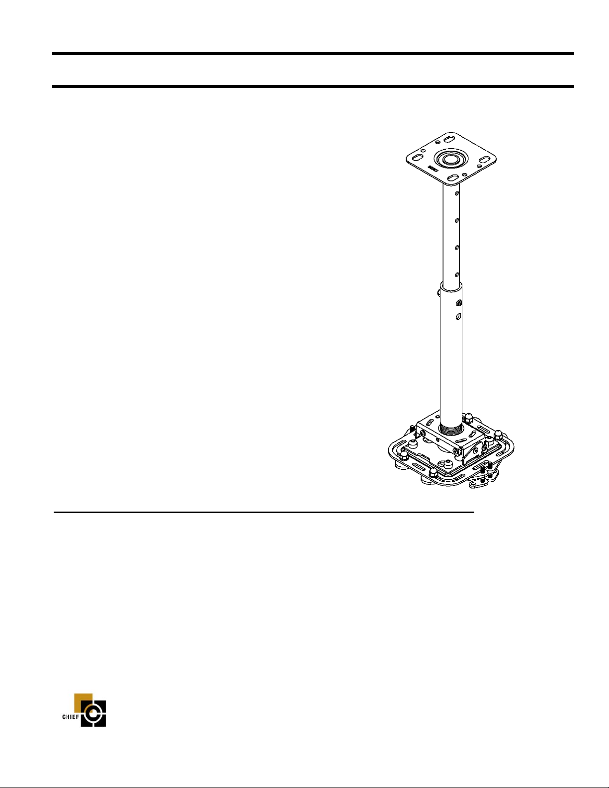
Universal
Ceiling Projector Mount Kit
The Universal Ceiling Projector Mount provides a unique, simplified method of ceiling mounting your inverted projector. This
low profile design offers three easy mounting methods (adjustable column, flush or threaded rod); roll, pitch and yaw adjustment; a cable management system; and a universal bracket that
allows quick projector disconnect without loss of registration.
The Universal Ceiling Projector Mount is constructed of heavy
gauge steel and designed to ensure proper projector ventilation.
Fast and precise image registration is achieved through the easy
roll, pitch and yaw adjustments built into the Universal Ceiling
Projector Mount.
BEFORE YOU BEGIN
• CAUTION: T o pr event damage to the Universal Ceiling Mount, which could affect or void the Factory wa rranty, thoroughly study all instructions and illustrations before you begin to install the Universal Ceiling Mount. Pay particular
attention to the “Important Precautions” on Page 1.
CHIEF MANUFACTURING INC.
1-800-582-6480 952-894-6280 FAX 952-894-6918 EUROPE 49 7031/76 91 41
8401 EAGLE CREEK PARKWAY chiefeurope@chiefmfg.com
SAVAGE, MINNESOTA 55378 USA
8832-000048 Rev. A00
©2004 Chief Manufacturing
www.chiefmfg.com
Printed in USA 09/04
Page 2

Instruction Manual MSP-DUK9000
IMPORT ANT WARNINGS AND CAUTIONS!
WARNING: A WARNING alerts you to the possibility of serious injury or death if you do not follow the instructions.
CAUTION: A CAUTION alerts you to the possibility of damage or destruction of equipment if you do not follow the cor-
responding instructions.
• WARNING: Improper installation can result in serious personal in jury! Make sure that the ceiling struc-
tural members can support a redundant weight factor five times
ceiling can not support this weight, reinforce the ceiling before installing the Universal Ceiling Projector
Mount.
• CAUTION: Inspect the unit for shipping damage. See “PARTS & DIMENSIONS” on page 2
the total weight of the equipment. If the
TOOLS REQUIRED FOR INSTALLATION
• Wire Cutter
• Socket Set
• Wrenches
•Scissors
• Allen Wrench (provided)
• Phillips screwdrivers, No. 1 and No. 2
NOTE: Other tools may be required depending on the
method of installation.
CONTENTS
PARTS & DIMENSIONS ................................... 2
INSPECT THE UNIT BEFORE
INSTALLING ...................................................... 4
PREPARE THE CEILING .................................. 4
General Guidelines .............................................. 4
UNIVERSAL CEILING PROJECTOR MOUNT
INSTALLATION PROCEDURES ..................... 5
Adjustable Column .............................................. 5
Standard Fasteners Secured to
a Wood Framing Member .................................... 6
Threaded Rod ....................................................... 6
PROJECTOR INTERFACE PLATE
ATTACHMENT PROCEDURES ....................... 7
PROJECTOR INTERFACE PLATE
INSTALLATION PROCEDURES ..................... 8
CABLE MANAGEMENT PROCEDURES ....... 8
SECURITY INSTALLATION (Optional) .............. 9
PROJECTOR ALIGMNMENT
INSTRUCTIONS ................................................. 10
Pitch/Roll/Yaw ..................................................... 10
1
Page 3

Instruction Manual MSP-DUK9000
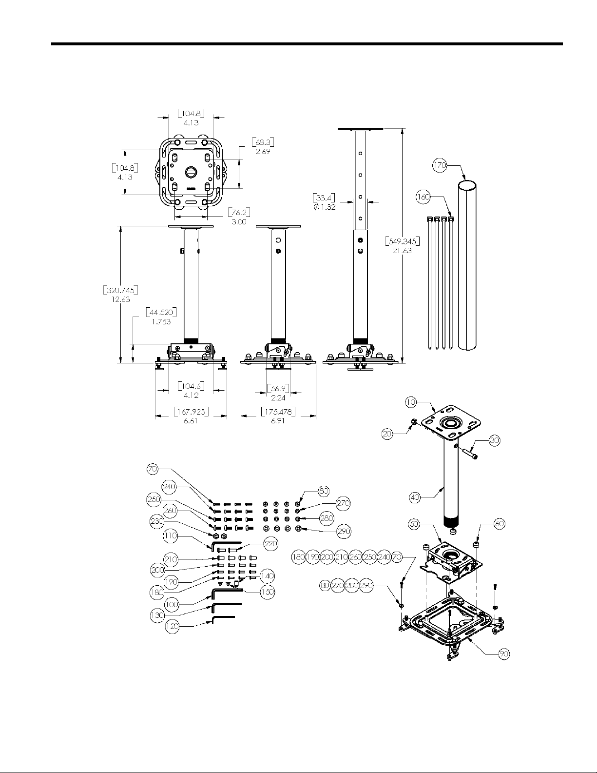
PARTS & DIMENSIONS
Table 1:
ITEM
10 Ceiling Column
20 1/4”-20 Locking Nut
30 1/4”-20 x 1 1/2” Security Bolt
40 1” NPT Column
50 Universal Projector Mount
60 Thumb Nut
70 M3 X 12mm Phillips Pan Head Screw
80 M3 Flat Washer (Standard)
90 Universal Mini SLB Assembly 1 240
100 3/16” Security Hex Key 1 250
110 5/32” Security Hex Key 1 260
120 3/32” Security Hex Key 1 270
130 5/32” Security Hex Key (Standard) 1 280
140 5/16-18 X .50” Security Set Screw 1 290
Nomenclature Qty
1
1
1
1190
1200
4210
4220
4230
ITEM
160 Cable Tie
170 Cable Wrap
180
Nomenclature Qty
M3 X 12mm Button Head Security Screw
M4 X 12mm Button Head Security Screw
M5 X 12mm Button Head Security Screw
M6 X 12mm Button Head Security Screw
1/4”-20 x .625” Button Head Security Screw
1/4”-20 NyLock Locknut
M4 X 12mm Phillips Pan Head Screw
M5 X 12mm Phillips Pan Head Screw
M6 X 12mm Phillips Pan Head Screw
M4 Flat Washer (Standard)
M5 Flat Washer (Standard)
M6 Flat Washer (Standard)
4
1
4
4
4
4
4
2
4
4
4
4
4
4
150 #10-24 X .25” Security Flat Head Screw 1
2
Page 4
Instruction Manual MSP-DUK9000
Acrobat Document
3
Page 5

Instruction Manual MSP-DUK9000
INSPECT THE UNIT BEFORE INSTALLING
1. Carefully inspect the Universal Ceiling Projector Mount for
shipping damage. If any damage is apparent, call your carrier
claims agent and do not continue with the installation until the
carrier has reviewed the damage.
NOTE: Read all instructions before starting installation.
2. Lay out components to ensure you have all the required parts
before proceeding (see “PAR TS & DIMENSIONS” on page 2).
PREPARE THE CEILING
Because of the wide variety of possible mounting situations,
Dukane Corporation can only provide general guidelines for installation. Study the following information carefully, and adapt it as
necessary to fit your specific installation.
WARNING: Be especially aware of the weight of the equipment, and the potential for personal injury or of damage to the
equipment if it is not adequately mounted.
The “General Guidelines” below and the information on the following pages cover the most common mounting situations:
• Suspended from an adjustable column secured to a structural cross brace in the ceiling.
• Standard fasteners secured to a wood framing member.
• Suspended from threaded rods that are secured to the structural cross brace
General Guidelines
• Carefully determine the position of the Universal Ceiling Projector Mount, and its distance from the screen. This will require
knowing the lens to screen distance (see projector specifications for set-up).
WARNING: Improper installation can result in serious personal injury! To avoid such injury, make sur e that the ceiling structural members can support a redundant weight factor five times the total weight of the equipment you intend
to support overhead. If they cannot, the ceiling must be reinforced before you install the Universal Ceiling Projector
Mount.
4
Page 6

Instruction Manual MSP-DUK9000
UNIVERSAL CEILING PROJECTOR MOUNT
INSTALLATION PROCEDURES
There are three common methods for installing the Universal Ceiling Projector Mount Series ceiling mount. The Universal Ceiling
Projector Mount can be suspended from an adjustable column, standard fasteners secured to a wood framing member, or threaded rods.
Joist
WARNING: Improper installation can cause serious personal
injury! Make sure that the ceiling structural members can
support a redundant weight factor five times the total
weight of the equipment you intend to support overhead.
The ceiling must be reinforced before you install the Universal Ceiling Projector Mount if the ceiling cannot support
a redundant weight factor five times the total weight of the
equipment.
Adjustable Column
Installation using an adjustable column, or 1” diameter schedule 40
steel pipe section with 1” NPT threads, requires securing the adjustable column or pipe to the building structure. W e suggest the use of
a backing block or Unistrut to secure the adjustable column or pipe
to a structural member (see Figure 2). Install the Universal Ceiling
Projector Mount on the adjustable column or pipe as follows:
1. Thread the Universal Ceiling Projector Mount onto the pipe a
minimum of 1/2” to allow for final yaw adjust men t.
2. Using Allen wrench provided, tighten the set screw to lock the
Universal Ceiling Projector Mount in position (see Figure 3).
3. Proceed to “PROJECTOR INTERFACE PLATE ATTACH-
MENT PROCEDURES” on page 7.
(4) 3/8" Nut
Backing Block
(4) 3/8" Washer
(4) 3/8" x 3"
Grade 5 Bolt
Adjustable Column
(4) 3/8" Nut
Unistrut
(1 5/8" x 1 5/8", 12 GA.)
Figure 2. Examples Using Adjustable Column
Tighten
YAW ADJUSTMENT SCREW
(+/- 180 DEGREES)
(8) 3/8" Washer
(4) 3/8" X 3" Grade 5 Bolt
Adjustable Column
Figure 3. Tighten Set Screw
5
Page 7

Instruction Manual MSP-DUK9000
Standard Fasteners Secured to a Wood Framing Member
The Universal Ceiling Projector Mount can be secured to a wood
framing member through four slotted holes in the Universal Ceiling
Projector Mount using four 1/4” diameter lag screws or, if the area
is accessible from above, four 1/4” diameter machine bolts, nuts,
and washers. Install the Universal Ceiling Projector Mount as follows:
1. Secure the Universal Ceiling Projector Mount to the wood
framing member.
Joist
Backing Block
(4) 1/4" Hex Nut
2. Proceed to “PROJECTOR INTERFACE PLATE ATTACHMENT PROCEDURES” on page 7.
Threaded Rod
Using four 1/4” diameter threaded rods, the Universal Ceiling Projector Mount can be secured to a typical unistrut, angle or channel
assembly at the overhead structural members (trusses or I-beams)
(see Figure 4). Install the Universal Ceiling Projector Mount as follows:
1. Secure one end of the threaded rod to the structural member.
2. Install a 1/4-20 hex nut on each threaded rod.
Universal
Projector Mount
(8) 1/4" Washer
(4) 1/4" Grade 5 Bolt
3. Install the Universal Ceiling Projector Mount on the threaded
rod.
NOTE: Holes in the Universal Ceiling Projector Mo unt allo w
socket wrench access without unit disassembly.
4. Secure the Universal Ceiling Projector Mount to the threaded
rod using eight 1/4-20 hex nuts.
(8) 1/4" Hex Nut
(8) 1/4" Flat Washer
(4) 1/4" Threaded Rod
Joist
Backing
Block
Universal
Projector
Mount
(8) 1/4" Flat Washer
(8) 1/4-20 HEX NUT
Figure 4. 1/4”Threaded Rod
6
Page 8

Instruction Manual MSP-DUK9000
PROJECTOR INTERFACE PLATE
ATTACHMENT PROCEDURES
Attach the bottom portion of the universal projector mount to the
projector as follows.
1. Loosen, but do not remove, acorn nuts securing arms of the
universal projector mount (see Figure 5).
2. Adjust front and back legs to mounting points. If there are only
three mounting points, remove one leg from the mount.
3. Adjust feet (rotate right to raise, left to lower), making sure to
allow for proper air ventilation and the mount is level with the
projector [some feet may need to be at different heights to keep
the mount level (M3, M4, M5 and M6 screws and washers
included)].
4. If the mounting holes are closer than a five inch diameter, raise
the feet all the way up so they will swing under the universal
interface bracket.
WARNING: You must use proper attaching hardware and
installation procedures. Failure to use proper
attaching hardware and installation procedures
may result in equipment damage or serious personal injury.
5. Determine proper screw size and depth (M3, M4, M5 and M6
included) for projector mounting and correct washers (M3,
M4, M5 and M6 included). If proper screw size is not included
with this unit, you must purchase the proper attaching hardware separately.
6. Secure (loosely) back two legs of universal projector mount to
the projector at mounting locations.
7. Secure (loosely) front two legs of universal projector mount to
the projector at mounting locations.
8. Move the universal projector mount to the center of gravity of
the projector.
9. Make sure the threaded studs on the plate are square in relation
to the front of the projector.
10. Tighten screws and acorn nuts securing the legs of the univer-
sal projector mount.
Figure 5. Projector Interface Plate to
Universal Ceiling Projector
Mount Attachment
11. Tighten hex nuts on the threaded studs to secure inserts at
proper positions.
Figure 6. Install the Projector Interface Plate on Your Projector
7
Page 9

Instruction Manual MSP-DUK9000
PROJECTOR INTERFACE PLATE
INSTALLATION PROCEDURES
The bracket attaches to the universal projector mount lifting and
sliding the screws of the bracket into the slot and four vee slots of
the universal projector mount (see Figure 5). Secure the bracket
using provided thumb screws and route cabling as necessary. Install
the universal projector mount on the bracket as follows:
NOTE: It is not necessary to remove the thumb nuts from the
studs to install and remove the projector.
1. Install, loosely, the 10-24 thumb nuts on the 10-24 studs of the
universal projector mount.
2. Align the four locating slots of the universal projector mount
with the 10-24 studs of the bracket and slide the bracket on the
universal projector mount to the limit of the slotted holes.
NOTE: The tapers of the thumb nuts should seat in the holes
of the bracket.
3. Secure the Bracket to the universal projector mount using the
thumb nuts (tapered side down).
4. Route cables as necessary.
CABLE MANAGEMENT
PROCEDURES
1. Route cables as necessary.
2. Secure cables using cable ties (see Figure 7).
3. Cut and install cable wrap.
Figure 7. Cable Routing Example
8
Page 10

Instruction Manual MSP-DUK9000
SECURITY INSTALLATION (OPTIONAL)
1. Using security wrench (provided), remove 5/16” standard set-
screw and replace using 5/16” security screw (see Figure 8).
2. Remove two screws from bottom of Projector Interface Plate,
preferably one from each corner.
3. Using security wrench and security screws from All-Points
Security package, secure Projector Interface Plate to projector.
4. Using security wrench (provided), replace screws in Projector
Interface Plate with undercut security screws from top from top
plate.
5. Remove two 1/4-20 x .5” round head carriage bolts and 1/4-20
acorn nut caps and replace using two security screws and lock
nut Nylocks (see Figure 8).
Figure 8. Adding Optional Security
9
Page 11

Instruction Manual MSP-DUK9000
PROJECTOR ALIGMNMENT INSTRUCTIONS
The Universal Ceiling Projector Mount can be adjusted for vertical
elevation (pitch), horizontal tilt (roll), and rotation (yaw). Once the
desired position is located and all the screws of the Universal Ceiling Projector Mount are tightened, the projector may be removed
from its location and replaced using the four thumb nuts without
loosing the registration of the projector. Align the projector as follows:
Pitch
Adjust pitch using the pitch adjustment screw located on each end
of the Universal Ceiling Projector Mount. Adjust pitch as follows:
1. Loosen the pitch adjustment screw on each side of the Universal Ceiling Projector Mount (see Figure 9).
2. Adjust projector angle to desired pitch.
3. Tighten the two pitch adjustment screws.
Roll
Adjust roll using two 1roll adjustment screws on the face and back
of the Universal Ceiling Projector Mount. Adjust roll as follows:
1. Loosen the roll adjustment screw on the face and back opposite
the pitch clamp (see Figure 9).
2. Adjust projector to desired roll position.
3. Tighten the roll adjustment screw.
Yaw
Adjust yaw by threading or unthreading the Universal Ceiling Projector Mount on the 1” pipe. Adjust yaw as follows:
1. Loosen the set screw (see Figure 9).
WARNING: Do not turn the Universal Ceiling Projector Mount
to the end of the pipe threads. The Universal Ceiling Projector Mount, Projector Interface Plate, and projector will
fall from the pipe if the Universal Ceiling Projector Mount
is unthreaded too far.
2. Adjust projector by turning the Universal Ceiling Projector
Mount on the 1” pipe to the desired yaw position.
NOTE: Overtightening the set screw may damage threads and
make adjusting yaw difficult. Make sure yaw adjustment is set
before tightening set screw.
Figure 9. Pitch, Roll, and Yaw Adjustment
3. Tighten the set screw.
10
 Loading...