

Page 1
INSTALLATION INSTRUCTIONS
MSB-6053
DISPLAY MOUNTING BRACKET
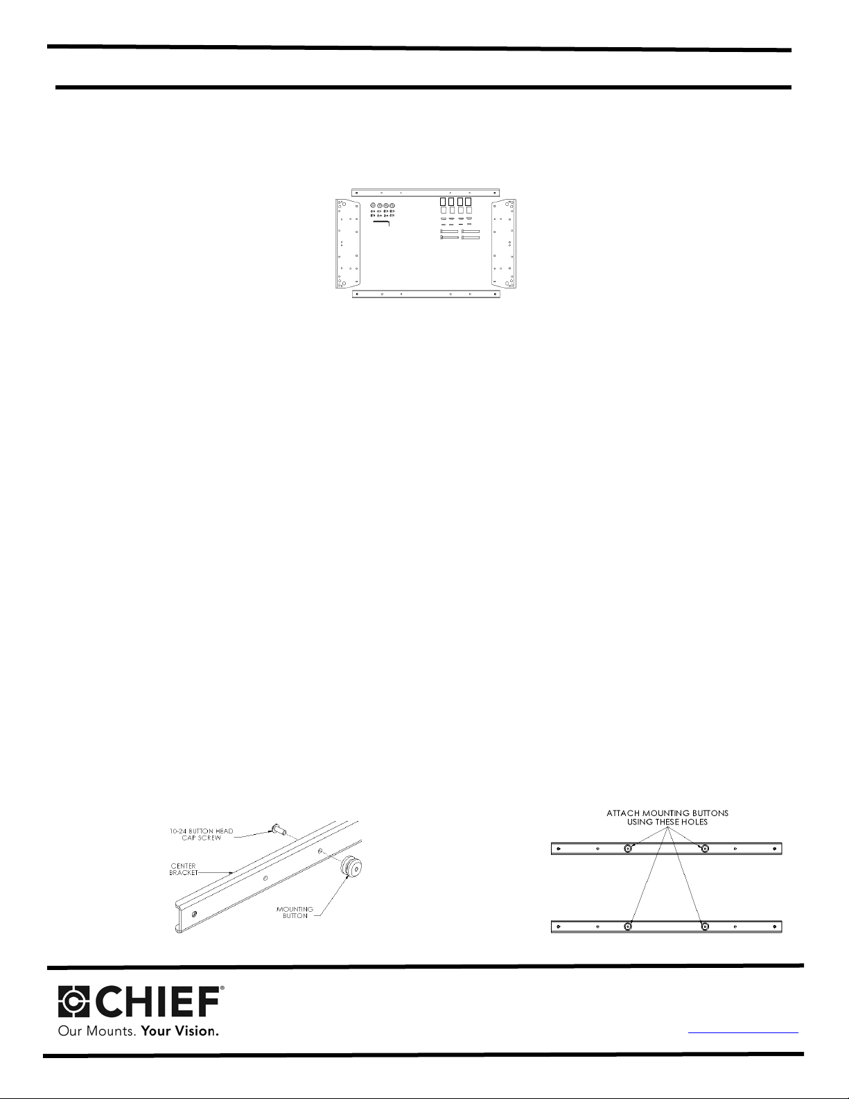
Prior to assembly, unpack carton completely and verify contents.
(2) Interface Side
(4) Mounting Buttons – Tapped (8) 10-24 x .5 Button Head Cap Screws
(4) M8 x 65mm Hex Head Cap Screws (4) 18mm x 8.3mm x 20mm Nylon Spacers
(4) M8 Flat Washers (4) Nylon Shoulder Washers
(1) 1/8” Allen Key (4) .74x.39x1.0” Nylon Spacers
BEFORE PROCEEDING, READ INSTALLATION INSTRUCTIONS COMPLETELY
Brackets (2) Interface Center Brackets
Figure 1
CAUTION!
WARNING!
NOT
E: If installing screen on a Chief J-series wall mount, proceed to Step 3 (J-Series VESA Interface Installation).
1. Chief Q-latch Button Installation (Used with MSR, MTR, MWH, MWR,
Using a 10-24 butt
mfered hole of mounting button (larger surface) facing bracket, to center brackets (four places) (s
cha
Figure 2 & Fi
2. Proceed to Step 4 (Side Bracket Assembly).
on head cap screw inserted from back side of bracket, secure mounting but
gure3).
DISPLAYS ARE EXTREMELY FRAGILE.
ALL COMPONENTS MUST BE SECURELY FASTENED TO A
STRUCTURAL MEMBER CAPABLE OF SUPPORTING 4 TIMES
THE COMBINED WEIGHT OF ALL COMPONENTS PLUS THE
EQUIPMENT BEING MOUNTED. IF IT CANNOT SUPPORT
THIS WEIGHT, THE STRUCTURE MUST BE REINFORCED.
THE MAXIMUM WEIGHT TO BE INSTALLED ON THE
INTERFACE IS 125 POUNDS (79.38 KG).
MCS and MCD mounts):
ton, with
ee
Figure 2
CHIEF M
Milestone AV Technologies.
1-800-582-6480 952-894-6280 FAX 952-894-6918
8401 EAGLE CREEK PKWY
SAVAGE, MINNESOTA 55378 USA
ANUFACTURING, a products division of
Figure 3
8840-000040 RevC
2008 Milestone AV Technologies
A Duchossois Group Company
www.chiefmfg.com
12/08
Page 2
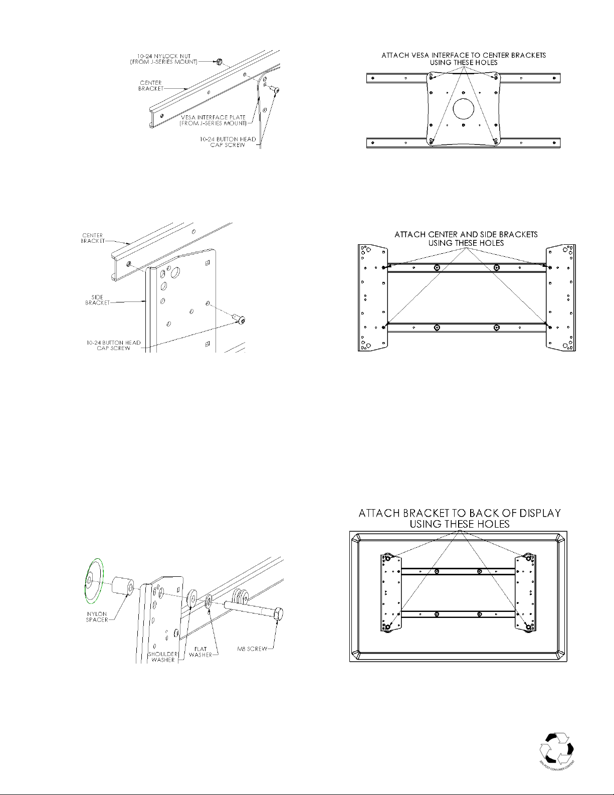
3. J-Series VESA Interface Installation: Using the 10-24 button head cap screws along with the 10-24 Nylock
nuts (provided with J-Series mount), attach VESA interface from J-Series mount to center brackets (see
Figure 4 & Figure 5).
Figure 4
Figure 5
4. Side Bracket Assembly: Attach center brackets to side brackets using the 10-24 button head cap screws (see
Figure 6 & Figure 7).
Figure 6
Figure 7
5. Bracket Installation: Place four nylon spacers over mounting holes on back of screen. Attach mounting
brackets to display using the M8 screws, shoulder and steel washers (see Figure 8 & Figure 9). Do not over
tighten screws.
NOTE: Select nylon spacers to use based upon the type of device being mounted. The remaining four
spacers will not be used.
6. Follow the Chief mount instruction manual for screen installation.
Figure 8
Figure 9
 Loading...