

Page 1

M30 Pro & M30 Pro ALU
INSTRUCTION MANUAL
We have the right to improve and update the machine.
The picture and the content are just for your reference.
IN20809
2017 © Chief Automotive Technologies CO9910.4 Rev. - 2/10/17
Page 2
1. Mechanical/Electrical/Illustration of Working Principle data
Electrical Data
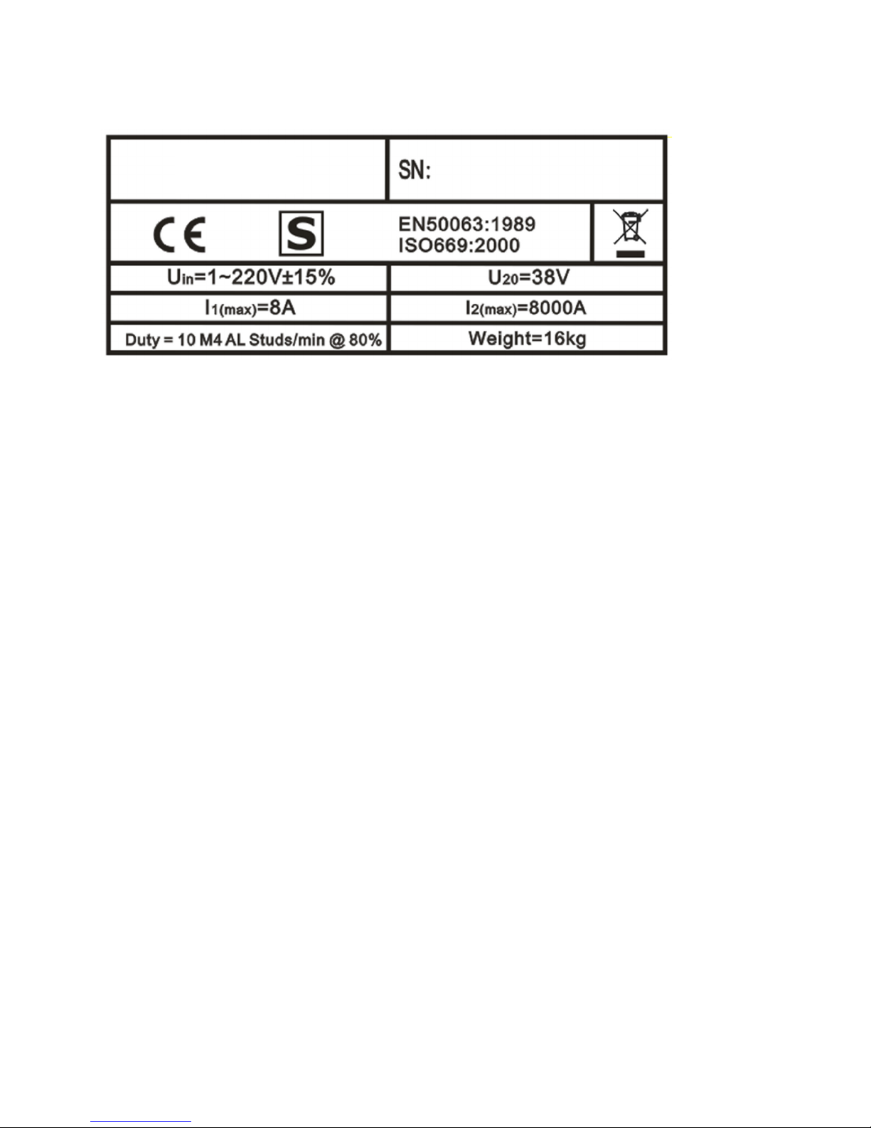
MODEL
SN— —Series number
CE, EN, ISO— —Certification standards
Uin— — Rated supply voltage
U20— —Range of rated AC no-load voltage and number of adjustable steps
I1 (max)— —Max input welding current
I2 (max)— —Max output welding current
Duty— —Duty cycle
Weight— —Weight of the welding equipment
2-1. Basic Machine Safety Information
(1) Input power is AC110 or AC220 ≥15A.
(2) Turn the switch “off “ when machine is not in use.
(3) Make sure to turn the switch “off “ when connecting or removing cables from the machine.
(4) When performing machine maintenance or repair the switch must be turned “off “ after 5 minutes.
(5) The stud clamp is inside the stud welding torch. The inside diameter of stud clamp must be suitable for the stud screw.
Do not use worn stud clamp.
(6) Stud welding may cause welding arcs and metal spatter, use appropriate safety protection and goggles.
(7) Make sure there are no flammable materials in the work area.
(8) The machine uses a special stud screw, use only original manufacturer parts.
(9) Pleases contact the manufacturer for the following situations: mechanical failure, reduce or increase the torch cable,
changes to the standard equipment.
2
Page 3

2-2. Stud welding and spot welding
2-2-1. Stud welding
When mounting the stud, the stud must extend past the three support legs about 2mm. Confirm the stud welding position.
Press the support legs on the work piece firmly. Make sure the work piece is smooth and clean. Press the torch trigger.
The stud screw will be welded on the base metal immediately. Check the stud welding strength. If the strength is not
sufficient, adjust the torch pressure, recharge, and repeat the steps. Traditional method such as rivets, lock screws, and
common welding typically damages the base metal. The stud welding process does not damage the base metal.
Diagram 1
1. The stud screw press
2-2-2. Spot welding
Diagram 2
1. Washer contact to work piece 2. Discharge-arc 3. Finish welding
Using this specific welding function heat will not affect the back side of work piece. The back of the work
piece will have a good appearance.
2-3. Stud welding visual test
the base metal
2. electric discharge,
start arc
3. Stud welding complete
Please refer to the pictures below for stud welding results. If the stud welding results are unsatisfactory adjust the power,
torch head pressure, or torch head height according to the instructions. (Note: only adjust one parameter at a time.)
1.
Voltage not enough
2.
Correct voltage
3
3.
Too high voltage
Page 4
2-4. Stud Welding Troubleshooting
(1) The ground cable or base metal are not making a good connection.
(2) Torch cable or ground cable is winding, coiled up, or crossed. Cables must be straight.
(3) The diameter of screw clamp and stud screw is not suitable, or screw clamp is worn.
(4) The base metal is dirty, rusty, painted, or other problem interfering with electricity conductibility.
(5) The torch is not suitable for the base metal or stud screw (material or diameter).
(6) The stud screw and the base metal are not making a good connection. (Keep the stud screw contacted to the base
metal vertically 90 degrees).
(7) The stud welding voltage is not correct.
(8) The capacitor is damaged, or limiting voltage.
(9) Welding torch must not have movement when welding. All feet must contact base metal.
(10) Stud screw extends too long or too short from the stud clamp.
(11) Base metal has distortion, dented or has moved while welding.
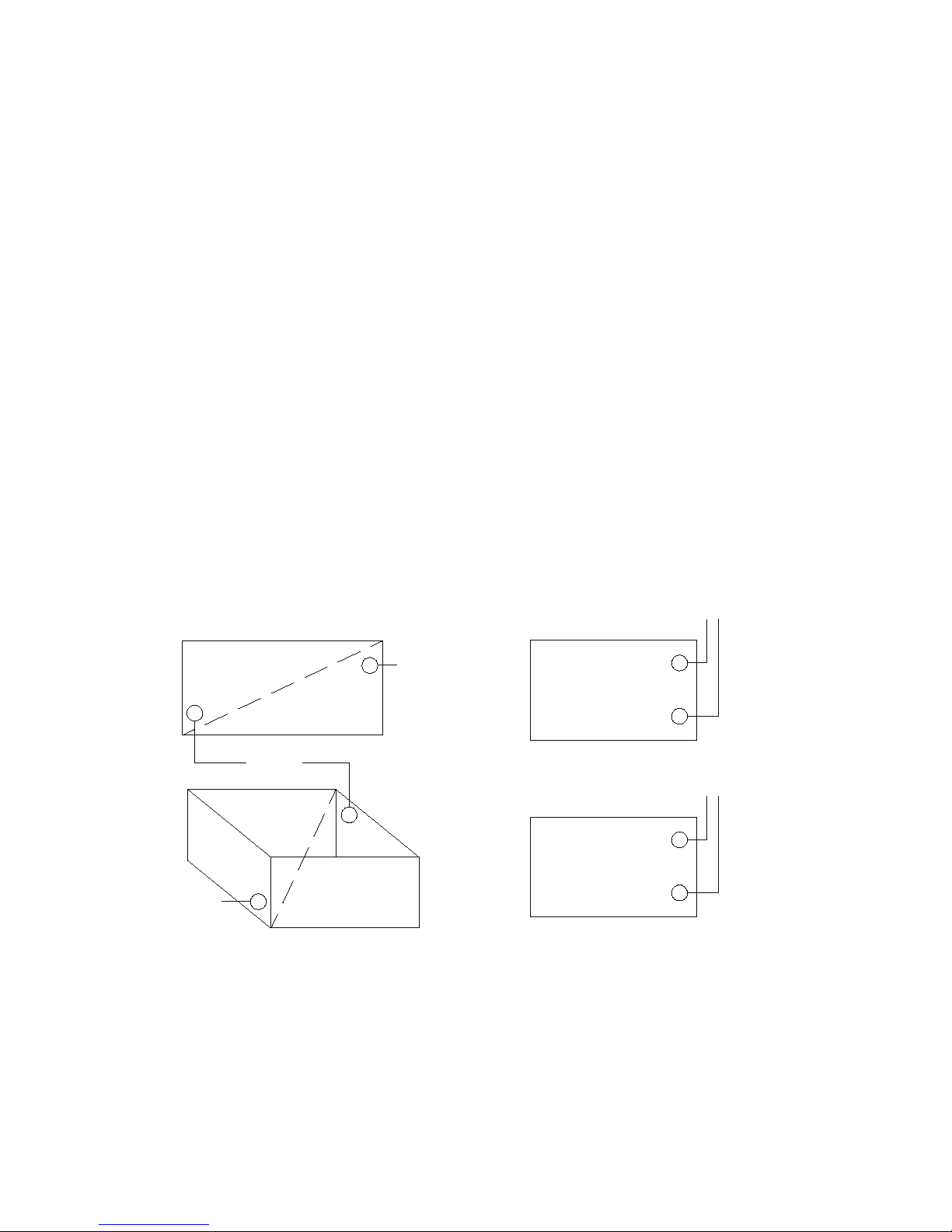
(12) Method for connecting the ground cable:
1. Cable must connect the base metal directly. Two ground cables must be connected.
2. The ground cable must connect to the diagonal position of the base metal. (Refer to the diagram as follow).
Correct Connection Incorrect Connection
EA RTH
EA RTH
EA RTH
EA RTH
EA RTH
4
Page 5
2-5. Welding cable connection
Note:
1). The torch cable and ground cable uses Euro type quick connectors. Push the plug to the end of the socket, torch cable
to “Torch” socket, ground cable to “Ground” socket, and turn right to lock connection.
2). The input cable and control cable connectors have screws. Lock the screw to fixed the
connector.
3). The ground cable must be a clamped to the base metal.
4). All cables must be kept straight .If the cable is winding it will imact with the stud welding performance.
For cable connections refer to the diagram.
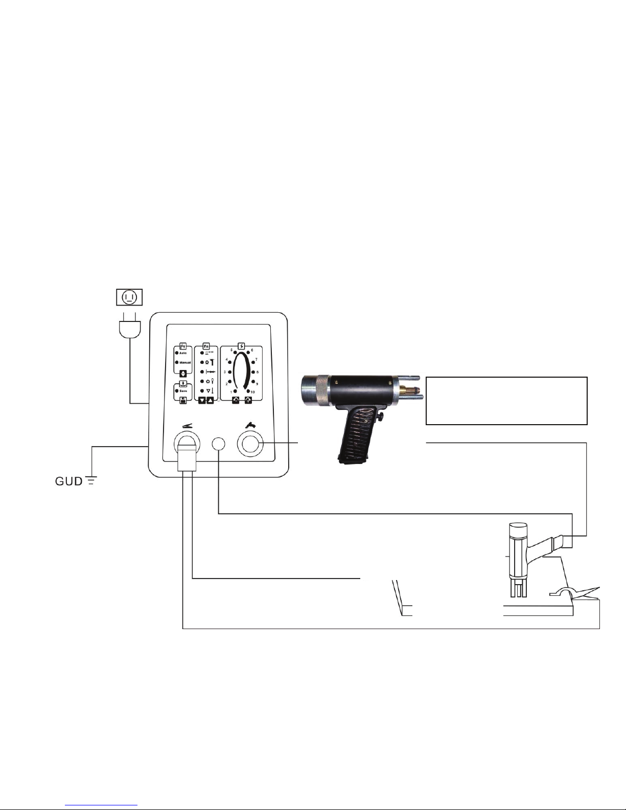
1) For stud welding-torch without ground cable (only for M30 Pro ALU) .
AC 110V/230V 5A Please confirm the input voltage before connecting to power supply.
CONTROL CABLE
GROUND CABLES (TWO CABLES)
Stud torch without ground cable.
Need to use two ground cables.
STUD WELDING TORCH CABLE
STUD WELDING TORCH
WORK PIECE
5
Page 6

2) For stud welding-torch with earth cable (only for M30 Pro ALU)
Stud torch with ground cable
Only use one ground cable
CONTROL CABLE
STUD WELDING TORCH CABLE
STUD WELDING TORCH
WORK PIECE
GROUND CABLE (ONE CABLE)
3) For spot welding (for M30 Pro/ M30 Pro ALU)
Spot welding torch
Use one or two ground cables
STUD WELDING TORCH CABLE
CONTROL CABLE
GROUND CABLES
SPOT WELDING TORCH
WORK PIECE
(ONE OR TWO CABLES)
6
Page 7

2-6. Controls on generator front panel
F
A--- There are two modes of operation, Auto mode and Manual mode.
B--- Save
Save the customer setting. The machine will load the save settings
every operation.
C\D--- Welding function selection. Press C and D for 2 seconds, the
machine will clear the save settings.
A
Φ
4~5 steel stud
(This function is only for M30 Pro ALU)
Φ
4~5 steel stud
B
C
E
round washer
quick puller slide hammer
star washer/steel tab
triangle washer/stud
E\F---Output power adjustment
The larger number the higher output power.
G--- Socket for work clamp
H--- Control socket for torch
I--- Socket for torch
J--- Power switch
K--- Input power cable
(Confirm the power voltage before use)
L--- Ground connector for the machine case
D
G H I
J
K
L
7
Page 8

2-7. Stud welding torch
2-7-1 torch (as diagram on right)
Torch operating principle:
Press the stud screw contact to the base metal.
The welding torch will discharge when contact is made.
That applies to :
Soft steel, stainless steel stud screw.
Length of stud screw less than 150mm.
2-7-2 Adjust the pressure and extend distance
3 support
feet
Screw
clamp
Torch head holder
Trigger
Shell
Pressure
adjustment
Handle
Extend 2.0mm
Diagram 4
Pressure spring
Spring adjustment
1. Stud screw must extend 2.0mm from 3 support feet,
shown in Diagram 4.
2. Turn the Spring adjustment left, stud welding heat
will increase, torch pressure will reduce.
3. Turn the Spring adjustment right, stud welding heat
will reduce, torch pressure will increase.
4. When torch pressure becomes low, remove back
cover and spring adjustment, then replace the pressure
spring.
8
Page 9

2-7-3 Stud screw clamp
Stud screw clamp carries the welding current. The diameter of the clamp must match stud screw diameter. If the clamp
and stud screw diameter do not match, the stud screw and clamp are easily damaged.
Socket wrench
for adjusting
screw clamp
Screw clamp
Clamp fixed screw
Gag lever post
Changing screw clamp
1. Use socket wrench to loose the clamp fixed screw.
2. Pull out screw clamp and gag lever post.
3. Insert new screw clamp and gag lever post to torch head. Make sure the diameter of the clamp is correct
and the length of the gag lever post is adjusted so the screw stud is located 1-2mm past screw clamp.
4. Use socket wrench to locking the clamp fixed screw.
Note: When using a new screw clamp, a pliers must be used to compress the groove of the screw clamp.
This will insure the screw camp and stud screw are connected properly.
The groove can expand with use and the stud screw will loosen.
Use pliers to clamp tight. This can extend the life of the screw
clamp.
9
Page 10

2-8. Operating process for stud welding
Note: Protect your eyes and your body when stud welding. Please operate the machine as follow.
2-8-1 Preparation for operation
(1) Keep the work piece free of dirt , oil, paint and rust.
(2) If the base metal is thin, it can cause the base to dent. Add a backer plate to support when stud welding.
(3) Select suitable stud welding torch, according as material, diameter, length of the stud screw.
(4) Make sure the diameter of the clamp is correct and the length of the gag lever post are adjusted correctly.
Install the screw clamp and gag lever post in the torch.
(5) Make sure the stud gun and cables are connected properly to the machine and workpiece. Connect the input cable and
turn on.
2-8-2 operate stud welding
(1) Insert the stud screw to screw clamp.
Note: Make sure the stud screw is inserted to the end of the screw clamp and makes contact to the gag lever post.
(2) Keep the 3 support feet contacted to the base metal. The torch should press on base metal vertically. (Diagram 25)
Note: Keep H-10torch in contact with the base metal, after inserting the stud screw.
(3) Press torch trigger. Discharge Stud welding is complete.
(4) After stud welding is complete, release the trigger, move the torch back vertically. (Diagram 26)
Test stud welding and setting suitable the welding strength before formal production.
Diagram 24
Screw clamp
Diagram 25 Diagram 26
Stud screw
Stud screw
Screw
3 support feet
10
Page 11

2-9. Maintenance
(1) The machine and torch must to keep away from dust, humidity, and rain.
(2) Avoid vibration, when moving the machine.
(3) Do not put the machine reversely, protect the machine.
(4) Keep unit clean and make sure all screws are tight. This will keep the machine in good working condition.
(5) Turn off the switch when not using the machine.
2-10. Select stud screw
Metal: soft steel, stainless steel, aluminum, titanium (Ti), brass , copper.
(1) Model F S TP
screw
diameter
total length
total length
thread
diameter
total length
(2) Dimension - outside thread-------- thread diameter * total length
- internal thread -------- screw diameter * total length - thread diameter
3. Safety precautions
WELDING CAN BE HARMFUL TO YOURSELF AND OTHERS. The user must be educated on hazards summarized below,
deriving from welding operations. For more detailed information, refer to the manual.
ELECTRIC SHOCK - May be fatal.
Install and ground the welding machine according to the applicable regulations.
Do not touch live electrical parts or electrodes with bare skin, gloves or wet clothing.
When operating, isolate yourself from both the ground and the work piece.
Make sure your working position is safe.
FUMES AND GASES - May be hazardous to your health. Use in well ventulated areas and use ventilators around the arc
to prevent gases from forming in the work area.
11
Page 12

ARC RAYS
May injure the eyes and burn the skin.
Protect your eyes with welding masks fitted with filtered lenses and protect your body with appropriate safety protection.
Protect others by installing adequate shields or curtains.
RISK OF FIRE AND BURNS
Sparks (sprays) may cause fires and burn the skin; make sure there are no flammable materials in the area, and wear
appropriate safety protection.
NOISE
This machine does not directly produce noise exceeding 80dB. The plasma cutting/welding procedure may produce noise
levels beyond said limit; users must implement all precautions required by law.
PACEMAKERS
The magnetic fields created by high currents may affect the operation of pacemakers. Wearers of vital electronic equipment (pacemakers) should consult their physician before beginning any arc welding, cutting, gouging or spot welding
operations.
EXPLOSIONS
Do not weld in the vicinity of containers under pressure, or in the presence of explosive dust, gases or fumes. All cylinders
and pressure regulators used in welding operations should be handled with care.
ELECTROMAGNETIC COMPATIBILITY
This machine is manufactured in compliance with the instructions contained in the harmonized standard and must be used
solely for professional purposes in an industrial environment. There may be potential difficulties in ensuring electromagnetic compatibility in non-industrial environments. IN CASE OF MALFUNCTIONS, REQUEST ASSISTANCE FROM QUALIFIED
PERSONNEL.
4. Trouble shooting
1. Check the source power.
2. Check the input cable.
No power
3. Check the main switch.
4. Please contact to the manufacturer.
1. Check the output cable for torch & ground.
2. Check the connection for torch & ground.
No weld
3. Check power fuse
4. check transformer, maybe over heat
5. Please contact to the manufacturer.
1. Check the power of fan.
Fan is not working
2. Check the fan, maybe something stuck in the fan.
3. Please contact to the manufacturer.
12
Page 13

Notes
13
Page 14

Notes
14
Page 15

Notes
15
Page 16

996 Industrial Dr.
Madison, IN 47250
Phone: 800.445.9262
Fax: 866.275.0173
www.chiefautomotive.com
Chief reserves the right to alter product specifications and/or package components without notice.
 Loading...