

Page 1
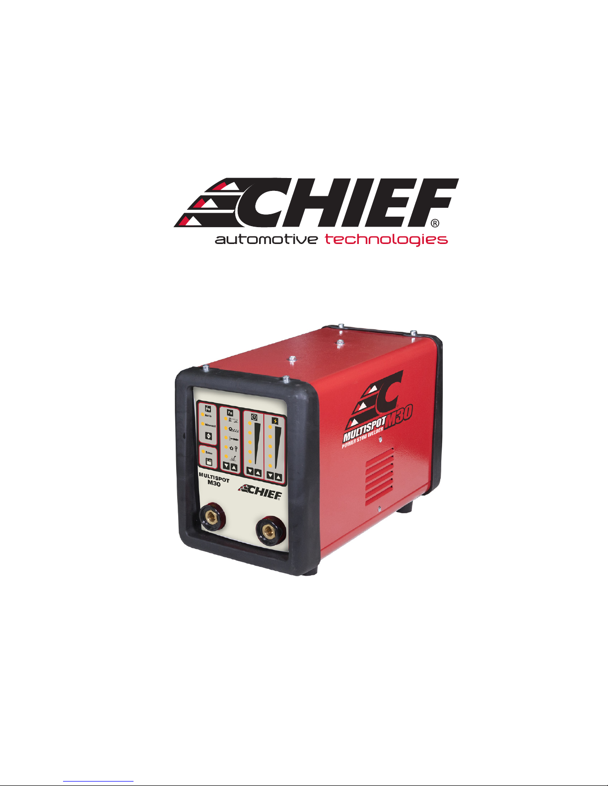
M30 SPOT WELDER
INSTRUCTION MANUAL
230V 1PH.
We have the right to improve and update the machine.
The picture and the content are just for your reference.
IN20808
2017 © Chief Automotive Technologies CO9910.4 Rev. - 2/09/17
Page 2

IMPORTANT: BEFORE STARTING THE EQUIPMENT, READ THE CONTENTS OF THIS MANUAL, WHICH MUST BE STORED
IN A PLACE FAMILIAR TO ALL USERS FOR THE ENTIRE OPERATIVE LIFE-SPAN OF THE MACHINE. THIS EQUIPMENT MUST
BE USED SOLELY FOR WELDING OPERATIONS.
1. SAFETY PRECAUTIONS
WELDING CAN BE HARMFUL TO YOURSELF AND OTHERS. The user must be educated on the hazards summarized below,
deriving from welding operations. For more detailed information, order the manual.
ELECTRIC SHOCK - May be fatal.
Install and ground the welding machine according to the applicable regulations.
Do not touch live electrical parts or electrodes with bare skin, gloves or wet clothing.
Isolate yourself from both the ground and the workpiece.
Make sure your working position is safe.
FUMES AND GASES - May be hazardous to your health.
Keep away from fumes.
Work in the presence of adequate ventilation, and use ventilators around the arc to prevent gases from forming in the work
area.
ARC RAYS - May injure the eyes and burn the skin.
Protect your eyes with welding masks fitted with filtered lenses, and protect your body with appropriate safety garments.
Protect others by installing adequate shields or curtains.
RISK OF FIRE AND BURNS
Sparks (sprays) may cause fires and burn your skin; be sure there are no flammable materials in the area and wear appropriate protection.
NOISE
This machine does not directly produce noise exceeding 80dB. The plasma cutting/welding procedure may produce noise
levels beyond said limit; users must implement all precautions required by law.
PACEMAKERS
The magnetic fields created by high currents may affect the operation of pacemakers. Wearers of vital electronic equipment (pacemakers) should consult their physician before beginning any arc welding, cutting, gouging or spot welding
operations.
EXPLOSIONS
Do not weld in the vicinity of containers under pressure, or in the presence of explosive dust, gases or fumes. All cylinders
and pressure regulators used in welding operations should be handled with care.
2
Page 3
ELECTROMAGNETIC COMPATIBILITY
This machine is manufactured in compliance with the instructions contained in the harmonized standard and must be used
solely for professional purposes in an industrial environment. There may be potential difficulties in ensuring electromagnetic compatibility in non-industrial environments.
IN CASE OF MALFUNCTIONS, REQUEST ASSISTANCE FROM QUALIFIED PERSONNEL.
2. GENERAL TECHNICAL DESCRIPTIONS
2.1 SPECIFICATIONS
This manual has been prepared with the intent of instructing the operator on how to install, operate, and properly maintain
this spot welding machine.
Upon receiving and unpacking the machine, make a careful inspection to ensure there are no damaged parts.
Should there be a claim for losses or damages it must be made by the purchaser directly to the shipper who handled the
goods.
When requesting information about this welding machine please state the machine’s part number and serial number to
ensure receiving accurate information relating to your machine.
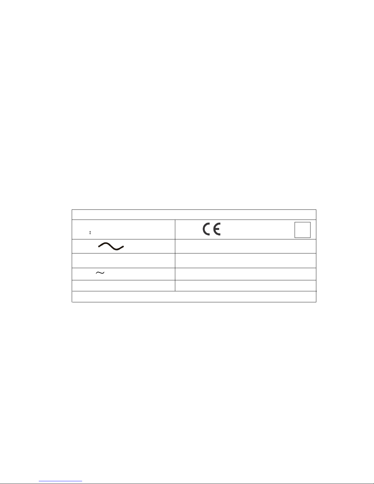
2.2 DESCRIPTION OF TECHNICAL SPECIFICATIONS
The contents are for your reference. Product may be updated without notice.
SPOT-X
EN50063:1989
SN:
ISO 669:2000
s
U20=
I 2CC =
1~ 50/60Hz
=
max
S
SPOT-X The model of the machine
SN Machine Serial Number which must appear on requests or inquiries concerning the machine.
CE ,EN ,ISO International standards
~ Alternating current (AC)
U20 Range of rated ac no-load voltage and number of adjustable steps
I2CC maximum short circuit current of the output corresponding to the minimum impedance
I2 Output welding current
Weight=
I 2=
U 1N=
Sn=
1~50/60 Single-phase input supply at 50 or 60 Hz
U1N Rated supply voltage
Smax Maximum power
Sn Power at normal duty cycle
Weight Weight of the welding equipment
3
Page 4

3. INSTALLATION
3.1 SETUP
Place the machine in a ventilated area.
Dust, dirt, or any other foreign material that may enter the machine can restrict ventilation which could affect the machine’s performance.
3.2 INPUT POWER CONNECTIONS
All sections concerning the installation of this machine must be read carefully.
This machine must be installed by skilled personnel.
Make sure that the input power plug has been disconnected before inspecting, maintaining, or servicing.
Connect the yellow-green wire to a good electrical ground.
Do not use water pipes as a ground conductor.
After a final inspection, the machine should be connected to the input supply voltage marked on the input power cord.
Mount a plug on the power supply cable that corresponds to the input power drawn by the machine.
3.3 CONNECTING the work return lead clamp
Attach the work return clamp to the work to be welded.
Make sure the ground clamp is tightly fastened to the work return cable and periodically check this connection remains
well tightened. A loose connection can cause weld current drops or overheating of the work return lead and clamp, which
creates the risk of burns from accidental contact with the work return lead. The weld circuit must not be placed deliberately in direct or indirect contact with the ground conductor.
If the work to be welded is attached deliberately to the ground by a protection lead, then the connection must be the most
direct possible and must be done using a lead that has a cross section that is at least equal to the cross section of the
work return lead being used for the weld circuit. The protection lead must also be attached to the work at the same spot as
the work return lead. To do so, a second ground clamp, fitted to the protection lead, must be attached next to the ground
clamp of the work return lead.
NOTE:
Small cross section and long extension cable will reduce the output current.
4
Page 5

Φ 4~5 steel stud
round washer/wiggle wire
quick puller slide hammer
star washer/steel tab
carbon heang/carbon shrink rod
4. DESCRIPTION OF CONTROLS
A
B
C D E F G H
A--- There is two modes for choice, Auto mode and Manual mode.
B--- Save
Save the customer setting. The machine will load the save settings every
operation.
C\D--- Welding function selection. Press C and D for 2 seconds, the machine will
clear the save settings.
E\F---Welding time adjustment
Adjust the welding timer, the larger number the longer welding time.
G\H--- output power adjustment
The larger number the higher output power
5
Page 6

5. THE WELDING MODE SETTING INSTRUCTIONS
1.) Auto mode
When setting Auto Mode, the machine can weld without pressing the torch switch. Make sure the torch, work cable, and
work piece have a good connection, wait for the delay timer, the machine will output power and welding. When setting
welding time up, the machine will stop output, lift the torch from the work piece. If the torch contacts the work piece again,
the machine will output again.
Note: The torch must not make constant contact with the work piece. After welding is completed and the torch and work
piece are still contacting, the machine will show an error warning. The power indicator LED will blink indicating an error,
you must lift the torch from the work piece before resuming welding.
2.) Manual mode
Contact the torch to the work piece and press the torch switch, the machine will begin welding. If the user selects the
welding timer, the machine will stop welding when the welding time is up. If the user selects continuous welding, the machine will keep welding utill the user turns off the torch switch.
6. INSTRUCTIONS FOR CAR REPAIR WORK
Spot Welding
1.) Power switch on, set suitable function.
(Auto, Manual-Timer, or Pulse)
2.) Set the spot welding current.
3.) Set work clamp.
4.) Spot-weld the washer.
Attention: The work clamp should be near the welding location.
6
Page 7

7. STUD WELDING AND SPOT WELDING
1.) Stud welding
When mounting the stud, the stud must extend past the three support legs about 2mm. Confirm the stud welding position. Press
the support legs on the work piece firmly. Make sure the work piece is smooth and clean. Press the torch trigger. The stud screw
will be welded on the base metal immediately. Check the stud welding strength. If the strength is not sufficient, adjust the torch
pressure, recharge, and repeat the steps. Traditional method such as rivets, lock screws, and common welding typically damages
the base metal. The stud welding process does not damage the base metal.
Diagram 1
2.) Spot welding
Diagram 2
1. Washer contact to work piece 2. Discharge-arc 3. Finish welding
Using this specific welding function heat will not affect the back side of work piece. The back of the work
piece will have a good appearance.
3.) Stud welding visual test
1. The stud screw press
the base metal
2. electric discharge,
start arc
3. Stud welding complete
Please refer to the pictures below for stud welding results. If the stud welding results are unsatisfactory adjust the power, torch
head pressure, or torch head height according to the instructions. (Note: only adjust one parameter at a time.)
1. Voltage not enough 2. Correct voltage 3. Too high voltage
7
Page 8

8. STUD WELDING TROUBLESHOOTING
1.) The ground cable or base metal are not making a good connection.
2.) Torch cable or ground cable is winding, coiled up, or crossed. Cables must be straight.
3.) The diameter of screw clamp and stud screw is not suitable, or screw clamp is worn.
4.) The base metal is dirty, rusty, painted, or other problem interfering with electricity conductibility.
5.) The torch is not suitable for the base metal or stud screw (material or diameter).
6.) The stud screw and the base metal are not making a good connection. (Keep the stud screw contacted to the base metal
vertically 90 degrees).
7.) The stud welding voltage is not correct.
8.) The capacitor is damaged, or limiting voltage.
9.) Welding torch must not have movement when welding. All feet must contact base metal.
10.) Stud screw extends too long or too short from the stud clamp.
11.) Base metal has distortion, dented or has moved while welding.
12.) Method for connecting the ground cable:
1.) Cable must connect the base metal directly. Two ground cables must be connected.
2.) The ground cable must connect to the diagonal position of the base metal. (Refer to the diagram as follow).
Correct Connection Incorrect Connection
EA RTH
EA RTH
EA RTH
EA RTH
EA RTH
8
Page 9

9. CARBON SHEET ROD
1. Power switch on, set suitable function.
(Manual-2T Ctrl)
2. Set output current (low current).
3. Press the torch trigger.
The output power is “ON” continually.
If torch trigger is released,
the output power is “OFF”.
Spot welding
S Do not use this function continuously for long
periods of time, transformer damage may occur.
9
Page 10

NOTES
10
Page 11

NOTES
11
Page 12

996 Industrial Dr.
Madison, IN 47250
Phone: 800.445.9262
Fax: 866.275.0173
www.chiefautomotive.com
Chief reserves the right to alter product specifications and/or package components without notice.
 Loading...