

Page 1
INSTALLATION INSTRUCTIONS
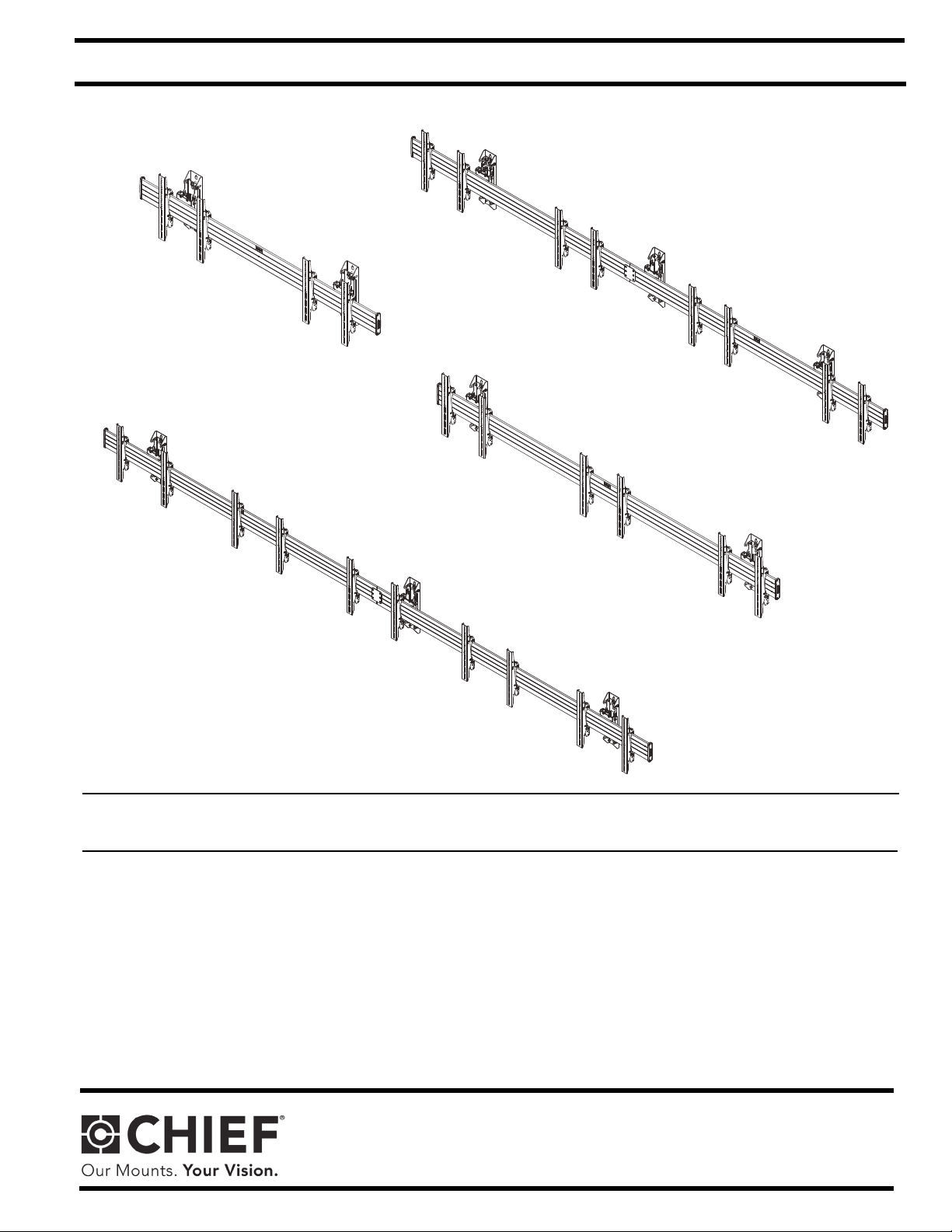
LWM2X1U
LWM4X1U
LWM3X1U
LWM5X1U
Wall-Mounted Menu Boards
Spanish Product Description
German Product Description
Portuguese Product Description
Italian Product Description
Dutch Product Description
French Product Description
LWM Series
Page 2
LWM Series Installation Instructions
LWM2X1U
LWM3X1U
LWM 4X1U
125 lbs 125 lbs
125 lbs 125 lbs
125 lbs 125 lbs 125 lbs
125 lbs 125 lbs 125 lbs
125 lbs 125 lbs
LWM5X1U
125 lbs 125 lbs
DISCLAIMER
Milestone AV Technologies and its affiliated corporations and
subsidiaries (collectively “Milestone”), intend to make this
manual accurate and complete. However, Milestone makes no
claim that the information contained herein covers all details,
conditions or variations, nor does it provide for every possible
contingency in connection with the installation or use of this
product. The information contained in this document is subject
to change without notice or obligation of any kind. Milestone
makes no representation of warranty, expressed or implied,
regarding the information contained herein. Milestone assumes
no responsibility for accuracy, completeness or sufficiency of
the information contained in this document.
Chief® is a registered trademark of Milestone AV Technologies.
All rights reserved.
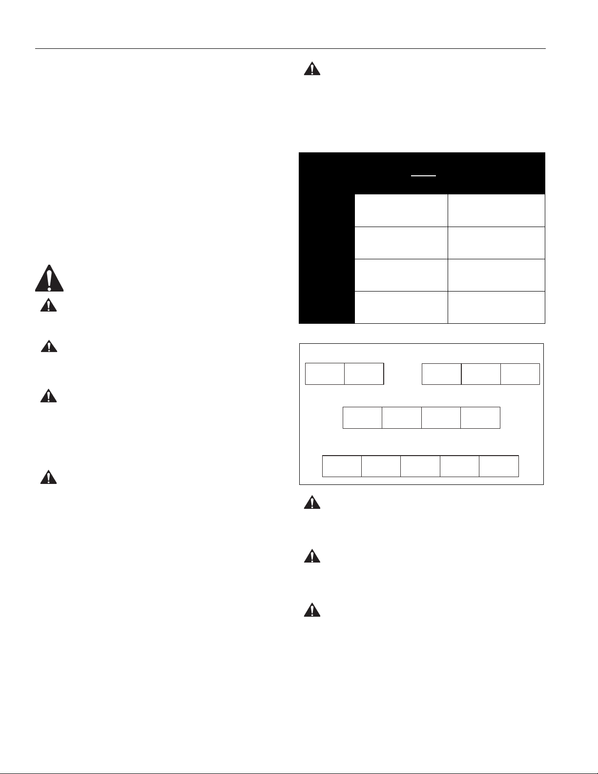
WARNING: Exceeding the weight capacity can result in
serious personal injury or damage to equipment! It is the
installer’s responsibility to make sure the combined weight of
all components located within the mounting system of the
LWM Series mounts does not exceed maximum weights
noted in table below.
MODEL Max Weight
Allowed for EACH
Display
LWM2X1U
LWM3X1U
125 lbs
(56.7 kg)
125 lbs
(56.7 kg)
Max Weight
Capacity of
Mounting System
250 lbs
(113.4 kg)
375 lbs
(170.1 kg)
IMPORTANT SAFETY INSTRUCTIONS
WARNING: A WARNING alerts you to the possibility of
serious injury or death if you do not follow the instructions.
CAUTION: A CAUTION alerts you to the possibility of
damage or destruction of equipment if you do not follow the
corresponding instructions.
WARNING: Failure to read, thoroughly understand, and
follow all instructions can result in serious personal injury,
damage to equipment, or voiding of factory warranty! It is the
installer’s responsibility to make sure all components are
properly assembled and installed using the instructions
provided.
WARNING: Failure to provide adequate structural strength
for this component can result in serious personal injury or
damage to equipment! It is the installer’s responsibility to
make sure the structure to which this component is attached
can support five times the combined weight of all equipment.
Reinforce the structure as required before installing the
component.
LWM4X1U
LWM5X1U
125 lbs
(56.7 kg)
125 lbs
(56.7 kg)
500 lbs
(226.8 kg)
625 lbs
(283.5 kg)
WARNING: Use this mounting system only for its intended
use as described in these instructions. Do not use
attachments not recommended by the manufacturer.
WARNING: Never operate this mounting system if it is
damaged. Return the mounting system to a service center for
examination and repair.
2
WARNING: Do not use this product outdoors.
IMPORTANT ! :
mounted to a 2" x 4" wood studs (16" on center) wall; or a bare
8" concrete wall. The LWM Series mounts are designed to
accept displays in the 40-55" (1016-1397mm) size.
The LWM Series mounts are designed to be
--SAVE THESE INSTRUCTIONS--
Page 3
Installation Instructions LWM Series
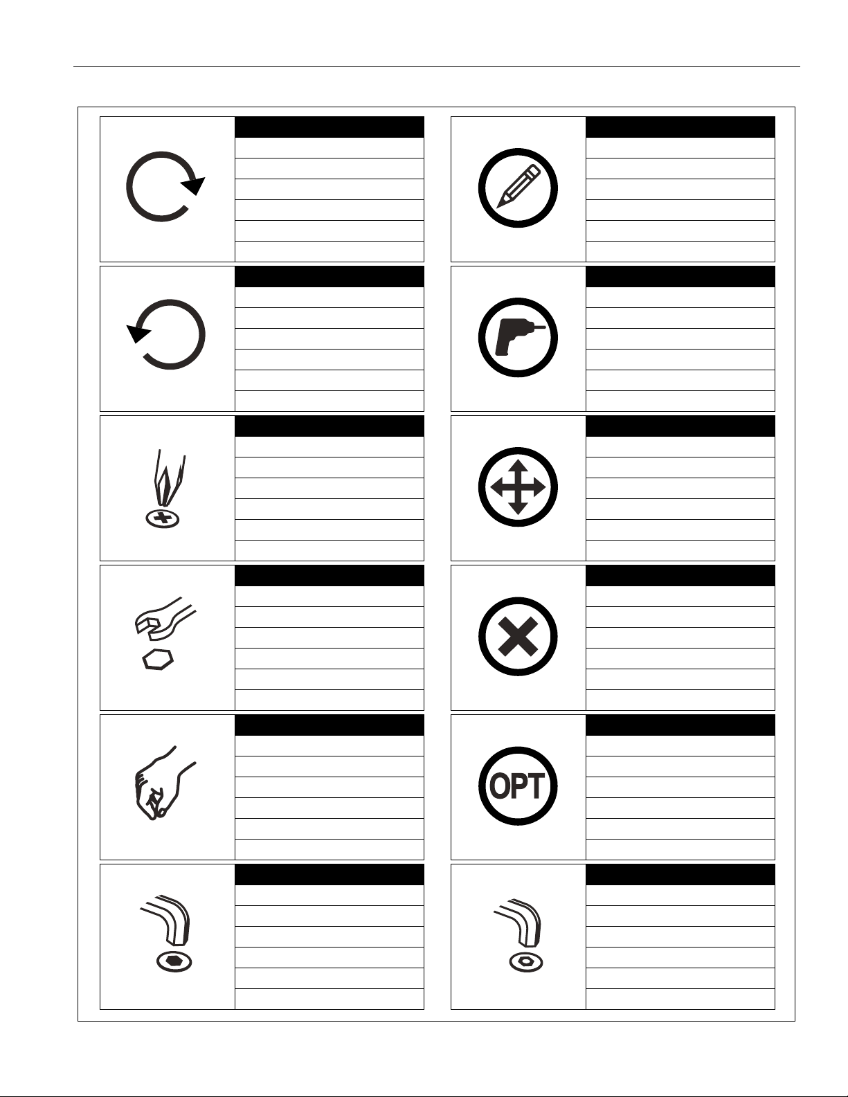
Tighten Fastener
Apretar elemento de fijación
Befestigungsteil festziehen
Apertar fixador
Serrare il fissaggio
Bevestiging vastdraaien
Serrez les fixations
Loosen Fastener
Aflojar elemento de fijación
Befestigungsteil lösen
Desapertar fixador
Allentare il fissaggio
Bevestiging losdraaien
Desserrez les fixations
Phillips Screwdriver
Destornillador Phillips
Kreuzschlitzschraubendreher
Chave de fendas Phillips
Cacciavite a stella
Kruiskopschroevendraaier
Tournevis à pointe cruciforme
Open-Ended Wrench
Llave de boca
Gabelschlüssel
Chave de bocas
Chiave a punte aperte
Steeksleutel
Clé à fourche
By Hand
A mano
Von Hand
Com a mão
A mano
Met de hand
À la main
Hex-Head Wrench
Llave de cabeza hexagonal
Sechskantschlüssel
Chave de cabeça sextavada
Chiave esagonale
Zeskantsleutel
Clé à tête hexagonale
Pencil Mark
Marcar con lápiz
Stiftmarkierung
Marcar com lápis
Segno a matita
Potloodmerkteken
Marquage au crayon
Drill Hole
Perforar
Bohrloch
Fazer furo
Praticare un foro
Gat boren
Percez un trou
Adjust
Ajustar
Einstellen
Ajustar
Regolare
Afstellen
Ajuster
Remove
Quitar
Entfernen
Remover
Rimuovere
Verwijderen
Retirez
Optional
Opcional
Optional
Opcional
Opzionale
Optie
En option
Security Wrench
Llave de seguridad
Sicherheitsschlüssel
Chave de segurança
Chiave di sicurezza
Veiligheidssleutel
Clé de sécurité
LEGEND
3
Page 4
LWM Series Installation Instructions
#2
7/32"
3/8"
1/2"
3/8"
M5
1/8"
3/16"
(all included)
M5
1/8"
3/16"
#3
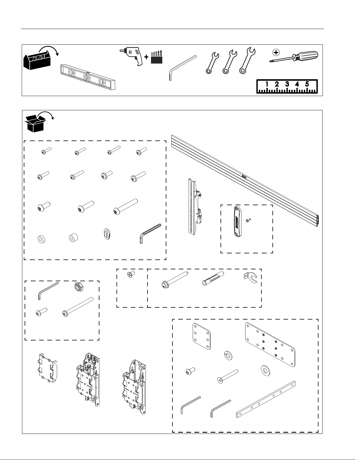
[Quantities listed in order for models: LWM2X1/LWM3X1/LWM4X1/LWM5X1]
DISPLAY ATTACH HARDWARE BAG (2/3/4/5)
A (8)
(Qty listed per hardware bag)
M4x16mm
B (6)
M4x20mm
C (6)
M4x25mm
D (6)
M5x16mm
E (6)
M5x20mm
F (6)
M5x25mm
G (6)
M6x16mm
H (6)
M6x25mm
I (6)
M8x20mm
J (6)
M8x30mm
K (4)
M8x50mm
L (8)
.75x.323x.25"
M (8)
.75x.344x.5"
N (8)
[Univ. washer]
P (1)
M5
(In section
marked "N")
Q (1-72"/1-108"/1-84"+1-72"/2-96")
[Horizontal mounting rail]
R (4/6/8/10)
[Interface bracket]
END CAP
KIT (1/1/1/1)
S (2)
[End cap]
T (4)
1/4-20 x 1/2"
T (1)
1/8"
U (2)
10-24
V (2)
10-24 x 5/8"
W (2)
10-24 x 2-1/4"
INTERFACE
(Qty listed per bag)
X (4)
5/16 x 1/2"
Y (2)
5/16 x 2-3/4"
Z (2)
[Anchor]
AA (2)
5/16"
(Qty listed per hardware bag)
WALL MOUNT HARDWARE (2/2/3/3)
BB (2/2/3/3)
[Height adjust plate]
CC (2/2/2/2)
[Outside wall upright]
DD (0/0/1/1)
[Center wall upright]
EE(1)
[Connect
bracket]
FF (8)
5/16"
GG (1)
[Connector plate]
HH (8)
5/16 x 5/8"
JJ (6)
10-24 x 1-1/2"
KK (8)
[Friction
washer]
LL (1)
1/8"
MM (1)
3/16"
NN (2)
[Tie bar]
MENU BOARD CONNECTOR KIT (0/0/1/1)
(Qty listed per hardware bag)
(Example shown: 72"
mounting rail for LWM2X1)
HARDWARE (2/3/4/5)
TOOLS REQUIRED FOR INSTALLATION
PART S
4
Page 5
Installation Instructions LWM Series
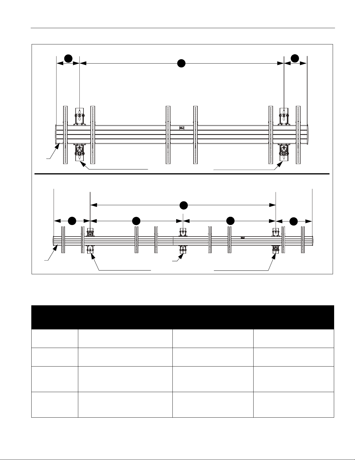
Attachment for LWM2X1 and LWM3X1
Attachment for LWM4X1 and LWM5X1
A
A
B
B
B
B
C
C
Outside wall uprights (CC)
Center wall upright (DD)
(LWM3X1 shown as example)
(LWM4X1 shown as example)
Rail
Rail
Outside wall uprights (CC)
WALL ATTACHMENT INFORMATION
Model A
(Outside wall upright spacing)
LWM 2X1
LWM 3X1
48" - 64" (1219 - 1626mm)
64" - 88" (1626 - 2235mm)
LWM 4X1
LWM 5X1
96" - 128" (2438 - 3251mm)
128" - 160" (3251 - 4064mm)
Figure 1
Ta b l e 1 : Wa l l U p r i g h t S p e c i f i c a t i o n s
B
(End of rail to wall upright)
"B" dimensions to be as close to
equal as possible. Not to exceed
12" (305mm).
"B" dimensions to be as close to
equal as possible. Not to exceed
22" (559mm).
"B" dimensions to be as close to
equal as possible. Not to exceed
30" (762mm).
"B" dimensions to be as close to
equal as possible. Not to exceed
32" (813mm).
(Wall upright spacing from
outside to inside)
N/A
N/A
Center wall upright is to be centered
as much as possible so that "C"
dimensions are as close to equal as
possible
Center wall upright is to be centered
as much as possible so that "C"
dimensions are as close to equal as
possible
C
IMPORTANT ! : DO NOT locate any of the wall uprights (CC or DD) directly behind any of the display interface
brackets (R).
5
Page 6
LWM Series Installation Instructions
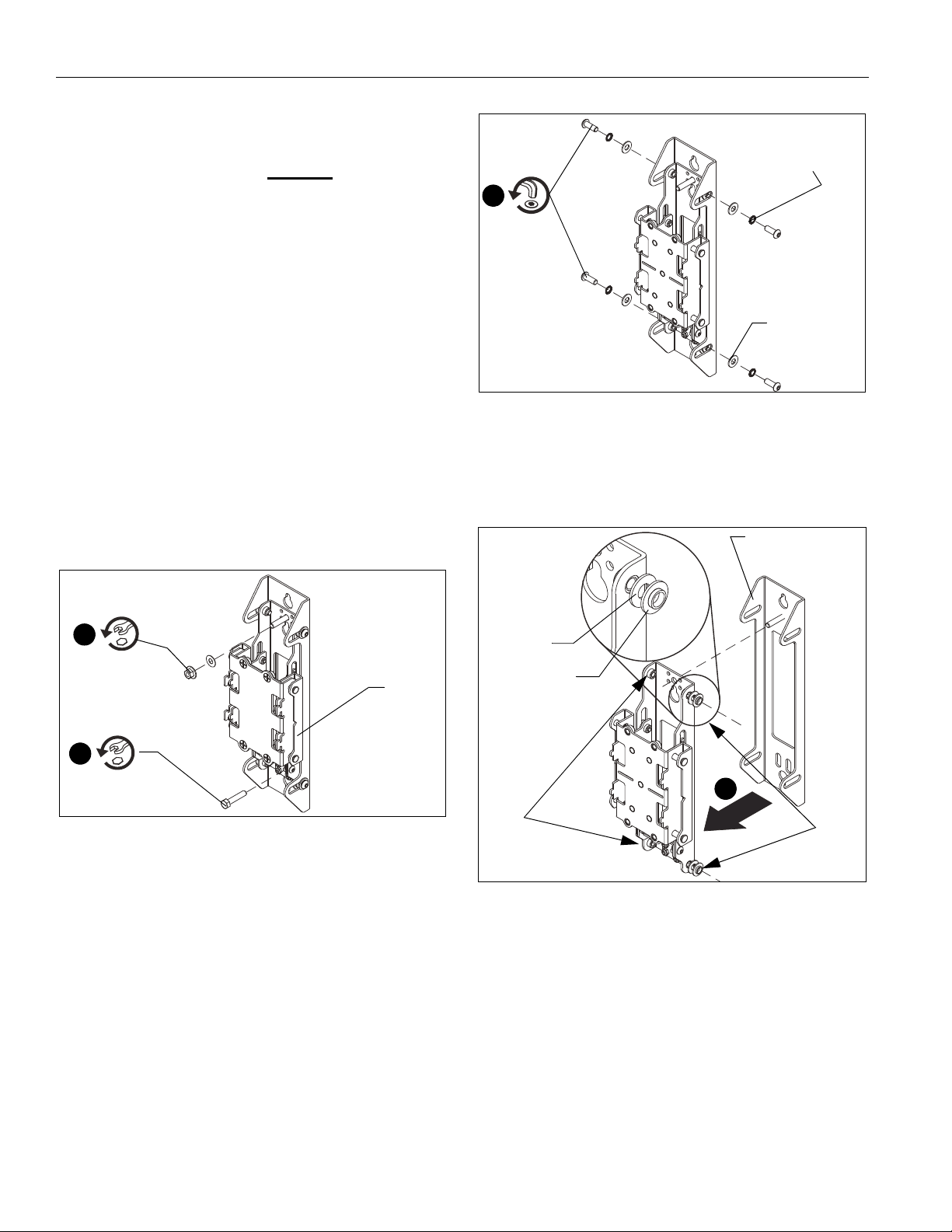
1
2
(CC)
3
Spring
washer
Flat
washer
Steel
Shoulder
Outer bracket
Steel and shoulder
washers removed
from four locations
washer
washer
Remove
steel and
shoulder washers
4
INSTALLATION
IMPORTANT ! : Refer to Dimensions section at end of
instructions to find specific LWM wall-mounted menu
board dimension requirements BEFORE
installation.
proceeding with
NOTE:
The outside wall uprights (CC) ship assembled to allow
height adjustment from the bottom. The uprights may
be changed to allow height adjustment from above the
menu boards. See following instructions for changing
the wall uprights.
If leaving wall uprights with height adjustment at the
bottom, proceed to ATTACH WALL UPRIGHTS
section.
Adjusting Wall Uprights
If the installation requires height adjustment from above the
menu boards, adjust the wall uprights (CC) BEFORE attaching
uprights to the wall.
IMPORTANT ! : Keep all hardware that is removed
during this adjustment process.
1. Remove flanged nut and washer from top of wall upright.
(CC) (See Figure 2)
2. Remove hex head screw from bottom of wall upright.
Figure 3
4. Remove wall upright assembly from outer bracket, while
removing one shoulder washer and one steel washer from
between outer bracket and wall upright assembly in four
locations. (See Figure 4)
Figure 2
3. Remove one button head screw, spring washer and flat
washer from four locations on side of wall upright. (See
Figure 3)
6
Figure 4
Page 7
Installation Instructions LWM Series
x 4
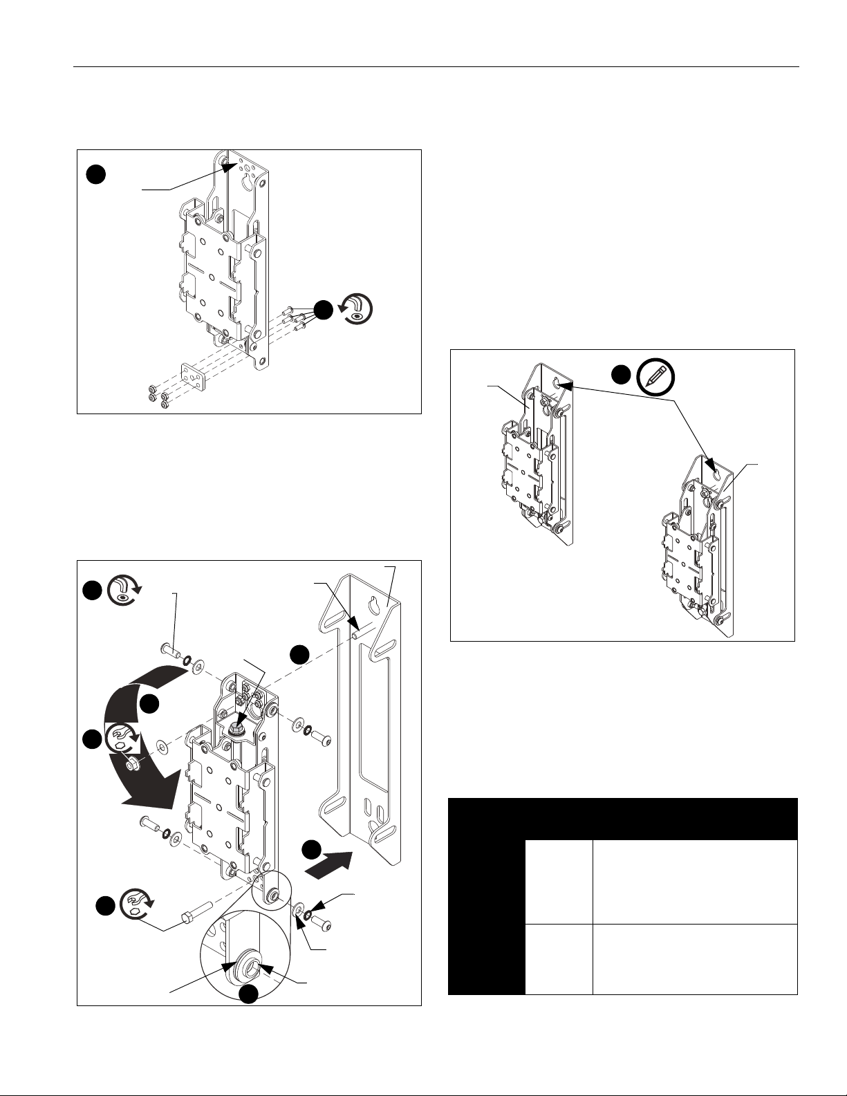
5
6
Re-install
plate
7
9
9
Height-adjust
screw
Threaded pem
8
Shoulder washer
Steel washer
Outer bracket
10
x 4
Spring
washer
Flat
washer
12
11
1
(CC)
(DD)
5. Remove four button head screws and nuts, and one small
metal plate from lower side within wall upright. (See Figure 5)
6. Reinstall metal plate at top of wall upright using same
hardware removed in Step 5. (See Figure 5)
Figure 5
7. Rotate wall assembly so that height-adjust screw is at top of
wall upright assembly. (See Figure 6)
8. Insert one shoulder washer and one steel washer between
outer bracket and wall upright assembly in four locations.
9. Insert wall upright assembly into outer bracket by placing
wall upright assembly onto threaded pem at top of outer
bracket.
10. Fasten one button head screw, spring washer and flat
washer into four locations on sides of wall upright.
11. Fasten hex head screw into bottom of wall upright.
12. Replace and tighten flanged nut and washer onto threaded
pem at top of wall upright. (See Figure 6)
Attach Wall Uprights
IMPORTANT ! : Reference Wall Placement Information
section (See Figure 1) and Table 1.
1. Use the outside wall upright (CC) or center wall upright (DD)
as a model to mark upper and lower pilot hole placement for
2 outside wall uprights (and center wall upright for LWM4X1
or LWM5X1 models) following wall placement information in
Figure 1 and Table 1. (See Figure 7)
Figure 6
Figure 7
IMPORTANT ! : See Parts drawing, Table 2 and
Installing to Wood Stud Walls or Installing to
Concrete Walls section for details on installing wall
brackets into wood studs or concrete.
Table 2: Fastener Information
WALL
TYPE
Wood stud
(2" x 4")
Concrete 3/8" x 3" 5/16 x 2-3/4" hex head lag (Y) &
PILOT
HOLE
7/32" x 3"
FASTENERS (see PARTS
drawing)
5/16 x 2-3/4" hex head lag (Y) &
5/16" slotted washer (AA).
Fasteners placed at stud
locations. Refer to Table 1 for
proper spacing for each model.
Fischer UX10x60 anchor (Z).
Refer to Tab le 1 for proper
spacing for each model.
7
Page 8

LWM Series Installation Instructions
(AA)
4
(Y) x 2
5
(CC)
8
8
1
7
6
Depth-adjust
screws x 4
11
2
(Z) x 2
1
8
9
(Y) x 2
6
10
(CC)
7
(AA)
Depth-adjust
screws x 4
13
Installing to Wood Stud Walls
1. Drill one 7/32" (5.5mm) pilot hole in stud at upper mounting
slot. (See Figure 8)
2. Partially install one 5/16 x 2-3/4" flanged lag bolt (Y) into
pilot hole but do not tighten to wall.
3. Hang outside wall upright (CC) [or center wall upright (DD)]
aligning upper mounting slot over lag bolt and level upright.
4. Place one slotted washer (AA) over flanged lag bolt. (See
Figure 8)
5. Tighten lag bolt to secure wall upright (CC or DD) to wall at
upper mounting slot. (See Figure 8)
Installing to Concrete Walls
1. Drill one 3/8" x 3-1/2" (9.5mm x 88.9mm) pilot hole at each
marking. (See Figure 9)
2. Install one anchor (Z) into each pilot hole using a hammer,
making sure that the anchor is flush with the wall.
3. Partially install one 5/16 x 2-3/4" flanged lag bolt (Y) into
pilot hole but do not tighten to wall.
4. Hang outside wall upright (CC) [or center wall upright (DD)]
aligning upper mounting slot over lag bolt and level upright.
5. Place one slotted washer (AA) over each flanged lag bolt.
(See Figure 9)
6. Tighten lag bolt to secure wall upright (CC or DD) to wall at
upper mounting slot.
Figure 8
6. Mark the attachment point for the lower mounting slot,
making sure the attachment point is located on the stud.
(See Figure 8)
7. Drill 7/32" (5.5mm) pilot hole at marking for lower mounting
hole. (See Figure 8)
8. Use one 5/16 x 2-3/4" flanged lag bolt (Y) and one 5/16"
slotted washer (AA) to attach each wall upright to the wall
through the lower mounting hole. (See Figure 8)
9. Repeat Steps 1 through 8 for remaining wall upright(s).
10. Adjust depth of wall uprights, if necessary, so that the face
of the wall uprights are all in the same plane across the
width of wall upright installation: (See Figure 8)
• Loosen button head screws (4 places)
• Adjust depth along depth-adjust slots.
• Tighten button head screws.
11. Proceed to Attach Mounting Rail section.
8
Figure 9
7. Mark the attachment point for the lower mounting slot. (See
Figure 9)
8. Drill 3/8" x 3-1/2" (9.5mm x 88.9mm) pilot holes at marking
for lower mounting hole. (See Figure 9)
9. Install an anchor (Z) into each pilot hole using a hammer,
making sure that the anchor is flush with the wall.
10. Use one 5/16 x 2-3/4" flanged lag bolt (Y) and one 5/16"
slotted washer (AA) to attach the wall upright to the wall
through the lower mounting hole. (See Figure 9)
11. Repeat Steps 1 through 10 for remaining wall upright(s).
12. Adjust depth of wall uprights, if necessary, so that the face
of the wall uprights are all in the same plane across the
width of wall upright installation: (See Figure 8)
• Loosen button head screws (4 places)
• Adjust depth along depth-adjust slots.
• Tighten button head screws.
Page 9

Installation Instructions LWM Series
(Q)
1
(NN) x 2
(back view of rail)
2
(JJ) x 3
(Q)
(EE)
(NN)
(back view of rail)
(GG)
(GG)
4
3
(HH) x 4
(FF)
(KK)
(NN)
(Q)
(Q)
(front view of rail)
(back view of rail)
(front view of rail)
(EE)
6
(HH) x 4
5
(JJ) x 3
5
(JJ) x 3
(GG)
(FF) x 4
(KK) x 4
ATTACH MOUNTING RAIL
IMPORTANT ! : If installing models LWM2X1 or
LWM3X1, proceed to Step 7.
LWM4X1/LWM5X1 Models Only
1. Insert two tie bars (NN) into the slots on one section of
mounting rail (Q). (See Figure 10)
Figure 10
2. Secure connect bracket (EE) to front of mounting rail (Q)
using three 10-24 x 1-1/2" flat head cap screws (JJ)
fastened through one side of connect bracket, mounting rail,
tie bars (NN) and into connector plate (GG). (See Figure 11)
4. Slide second section of mounting rail (Q) over tie bars (NN)
and bring it flush to first section of mounting rail. (See
Figure 12)
Figure 12
5. Secure connect bracket (EE) to front of second section of
mounting rail (Q) using three 10-24 x 1-1/2" flat head cap
screws (JJ) fastened through one side of connect bracket,
mounting rail, tie bars (NN) and into connector plate (GG).
(See Figure 13)
6. Additionally fasten connector plate (GG) using four
5/16 x 5/8" button head cap screws (HH), four 5/16" split
washers (FF), and four friction washers (KK). (See Figure 13)
3. Additionally fasten connector plate (GG) using four
Figure 11
5/16 x 5/8" button head cap screws (HH), four 5/16" split
washers (FF), and four friction washers (KK). (See Figure 12)
Figure 13
9
Page 10

LWM Series Installation Instructions
7
(T) x 2
(S)
(Q)
(back view of rail)
8
(BB)
(Q)
(front view of rail)
10
(X) x 4
9
9
(BB)
(CC)
(Q)
(front view of rail)
11
(T) x 2
(Q)
(S)
(back view of rail)
7. Attach one end cap (S) with two 1/4-20 x 1/2" Phillips head
screws (T) to end of mounting rail (Q). (See Figure 14)
Figure 14
8. Slide height adjust plates (BB) into open end of mounting
rail (Q). (See Figure 15)
• LWM2X1/LWM3X1: Insert two plates (BB)
• LWM4X1/LWM5X1: Insert three plates (BB)
Figure 15
9. Hook height adjust plates (BB) over wall uprights (CC or
DD). (See Figure 16)
NOTE: Hook all height adjust plates (BB) over wall uprights
(CC or DD), and approximately center mounting rail
over the span of the wall uprights (CC or DD) BEFORE
proceeding to next step.
10. Fasten mounting rail (Q) to wall uprights using four
5/16 x 1/2" Phillips flat head screws (X) through height
adjust plate (BB) and into wall uprights (CC or DD) and
tighten all screws. (See Figure 16)
Figure 16
11. Attach one remaining end cap (S) with two 1/4-20 x 1/2"
Phillips head screws (T) to end of mounting rail (Q). (See
Figure 17)
Figure 17
10
Page 11
Installation Instructions LWM Series
Height-adjust
screw
Depth-adjust
screws x 4
(Front view)
(R)
1
Latch
mechanism
(L or M)
(N)
(R)
Center of
bracket
(A-K)
4
3
Adjust and Level Mounting Rail
1. Adjust the height of the mounting rail via the wall upright, as
necessary, to level the mounting rail on the wall. (See
Figure 18)
• Turn the wall upright height-adjust screw clockwise
(viewed from bottom) to raise the mounting rail.
• Turn the wall upright height-adjust screw counter-
clockwise (viewed from bottom) to lower the mounting
rail.
2. Adjust the depth of the mounting rail via the wall upright, as
necessary, to make the mounting rail distance from the wall
consistent.
• Loosen depth-adjust button head screws, and move
mounting rail away or toward the wall, as necessary.
• Tighten depth-adjust button head screws.
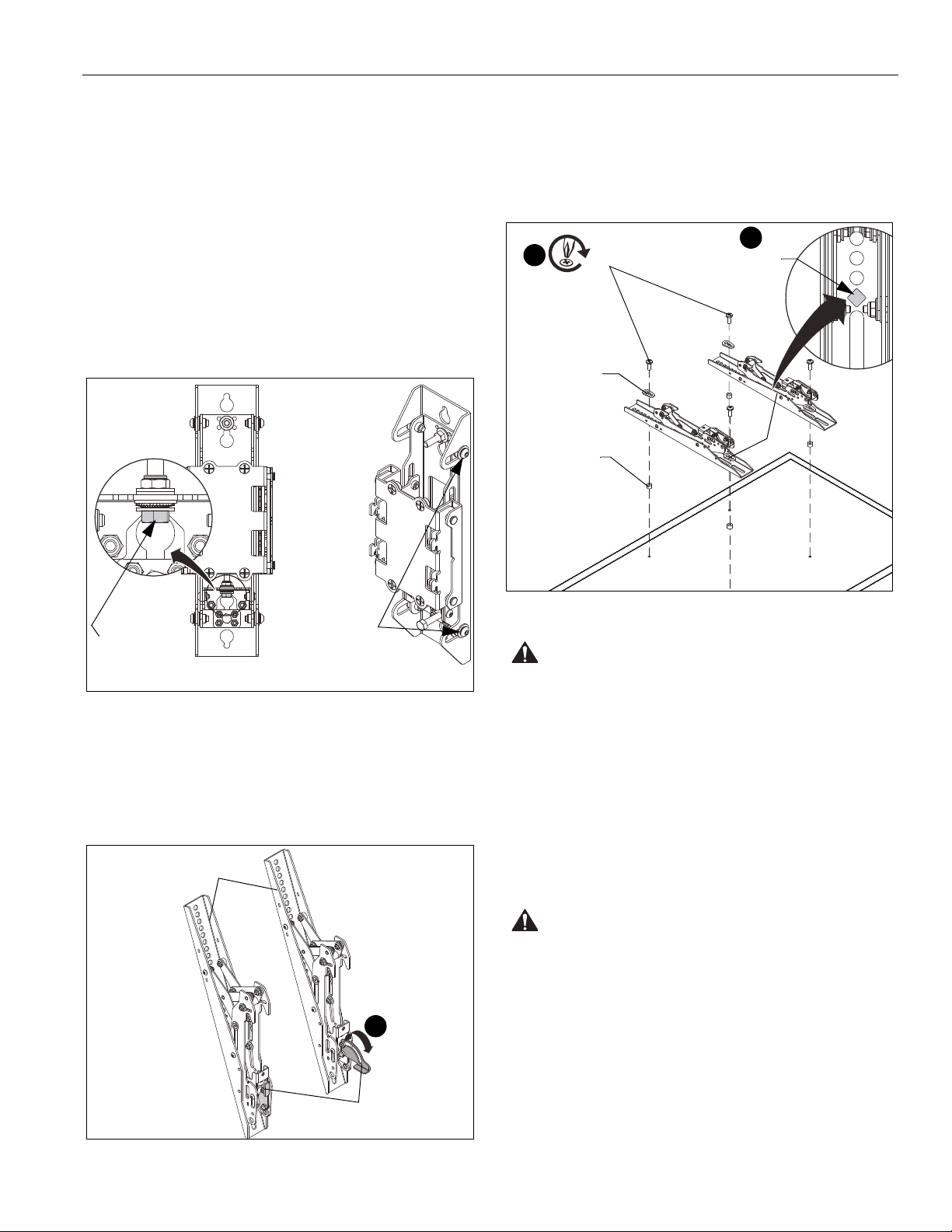
2. Place displays face down on a soft, non-abrasive surface.
3. Align the center of the interface bracket (R) with center of
screen. (See Figure 20)
NOTE: The diamond-shape hole in the bracket corresponds to
the center of the mount.
Figure 20
WARNING: IMPROPER INSTALLATION CAN LEAD TO
DISPLAY FALLING CAUSING SERIOUS PERSONAL
Figure 18
INSTALL INTERFACE BRACKETS TO
DISPLAYS
1. Lower the latch mechanism on each interface bracket (R).
(See Figure 19)
INJURY OR DAMAGE TO EQUIPMENT! Using screws of
improper size may damage your display. Properly sized
screws will easily and completely thread into display
mounting holes. If spacers are required, be sure to use longer
screws of the same diameter.
4. Select correct screws, spacers (if necessary) and universal
washers from the hardware bag (A-N) and attach brackets
(R) to back of screen. (See Figure 20)
ATTACH DISPLAYS TO MOUNTING RAIL
WARNING: IMPROPER INSTALLATION CAN LEAD TO
DISPLAY FALLING CAUSING SERIOUS PERSONAL
INJURY OR DAMAGE TO EQUIPMENT! The displays must
be located approximately evenly across the length of the rail.
1. Ensure that the latch mechanisms on interface brackets (R)
are already lowered. (See Figure 19)
Figure 19
11
Page 12

LWM Series Installation Instructions
2
3
3
Latch
mechanism
4
(V) x 2
5
Lock at
Lock at
Lock at
Tilt
friction
bolt
1
2
4
(Displays not shown)
3
(W)
(U)
0° tilt
10° tilt
20° tilt
2. While supporting both sides of display, lower display onto
one side of mounting rail, hooking top of interface brackets
onto front of mounting rail. (See Figure 21)
3. Raise the latch mechanism on both interface brackets to
lock bracket in place. (See Figure 21)
Interface Bracket Adjustment
Tilt
The interface brackets allow 0° to 20° tilt, and can be locked at
0°, 10° and 20° tilt.
1. If necessary, loosen button head tilt friction bolt (located on
side of interface bracket). (See Figure 23)
2. Adjust tilt as required. (See Figure 23)
3. The tilt may be locked at 0°, 10° and 20° using one
10-24 x 2-1/4" Phillips head screw (W) and one 10-24 lock
nut (U) per interface bracket. (See Figure 23)
4. Tighten tilt friction bolt as necessary.
Figure 21
4. Fasten bracket against ceiling mount extrusion using one
10-24 x 5/8" button head cap screw (V). (See Figure 22)
5. Repeat for other interface bracket.
Figure 23
Figure 22
6. While supporting both sides of each remaining display, lower
display onto mounting rail, hooking top of interface brackets
onto front of mounting rail. (See Figure 21)
7. Repeat Steps 3 through 5 for each additional display.
12
Page 13

Installation Instructions LWM Series
Padlock
(Optional)
(Displays not shown)
OPTIONAL: Security
1. OPTIONAL: Add padlock (not included) to each interface
bracket to lock display to menu board. (See Figure 24)
Figure 24
13
Page 14

LWM Series Installation Instructions
RECOMMENDED SPACING
48" to 64"
1220 to 1625 mm
72.00
1828.8
MOUNT SHOWN WITH HEIGHT ADJUST CENTERED
6.78
172.3
MAX. DEPTH
DIMENSIONS: INCHES
[MILLIMETERS]
LWM2X1U
DIMENSIONS
14
Page 15
Installation Instructions LWM Series
16.75
425.5
9.5
O
LWM2X1U
DIMENSIONS: INCHES
[MILLIMETERS]
DIMENSIONS (continued)
0.38
HOLE F
15
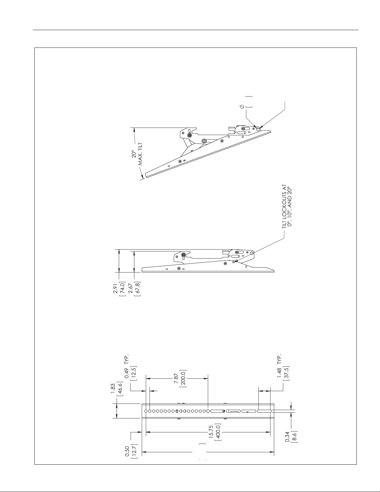
Page 16
LWM Series Installation Instructions
108.00
2743.2
0.34
8.6
TYP.
7.87
200.0
DIMENSIONS: INCHES
[MILLIMETERS]
LWM3X1U
DIMENSIONS (continued)
16
Page 17
Installation Instructions LWM Series
9.47
MINIMUM
DEPTH
MAXIMUM
DIMENSIONS: INCHES
[MILLIMETERS]
LWM3X1U
DIMENSIONS (continued)
240.6
17
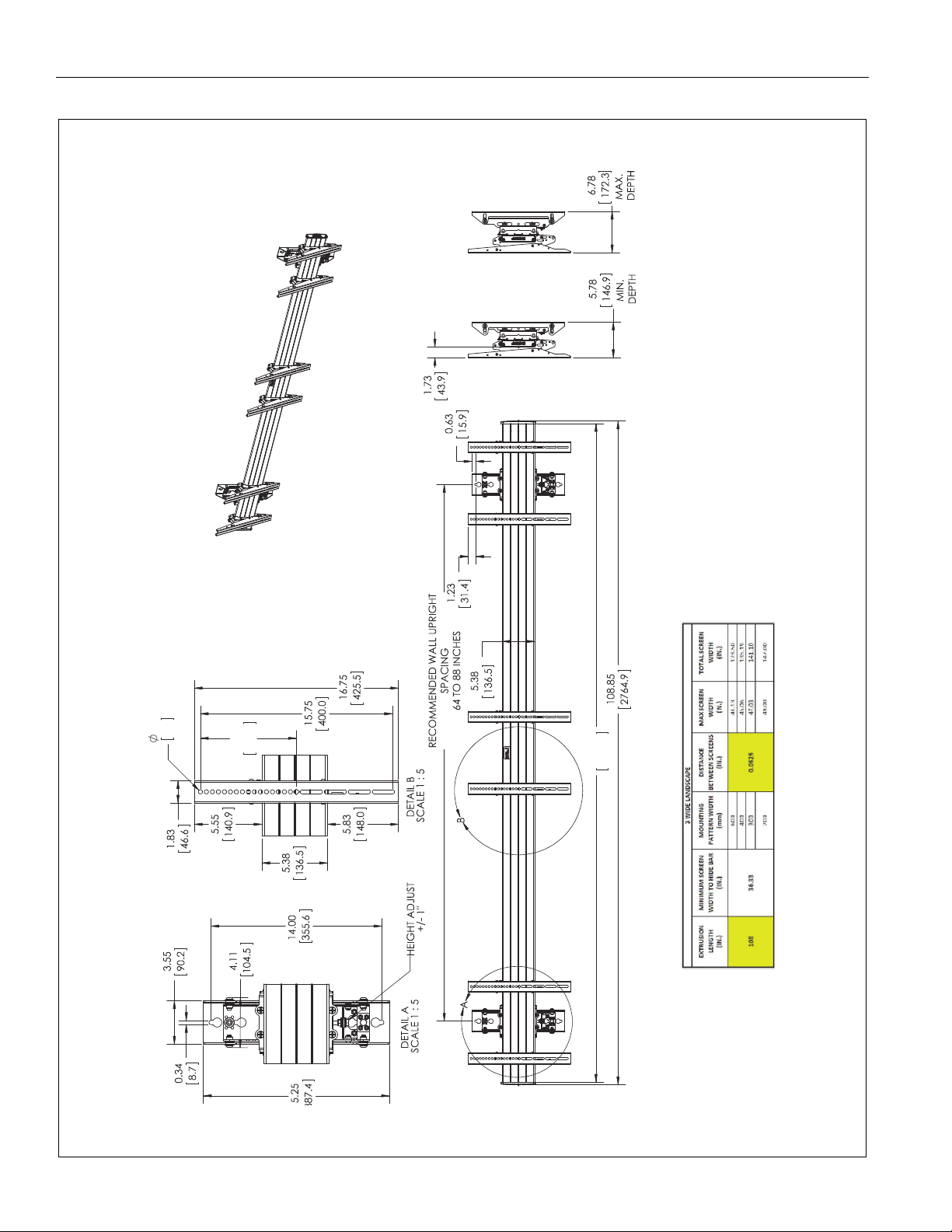
Page 18
LWM Series Installation Instructions
156.03
3963.2
0.34
8.6
0.49
12.5
DETAIL B
MOUNT IS SHOWN WITH HEIGHT ADJUST CENTERED
LWM4X1U
DIMENSIONS: INCHES
[MILLIMETERS]
DIMENSIONS (continued)
TYP.
TYP.
SCALE 1 : 5
18
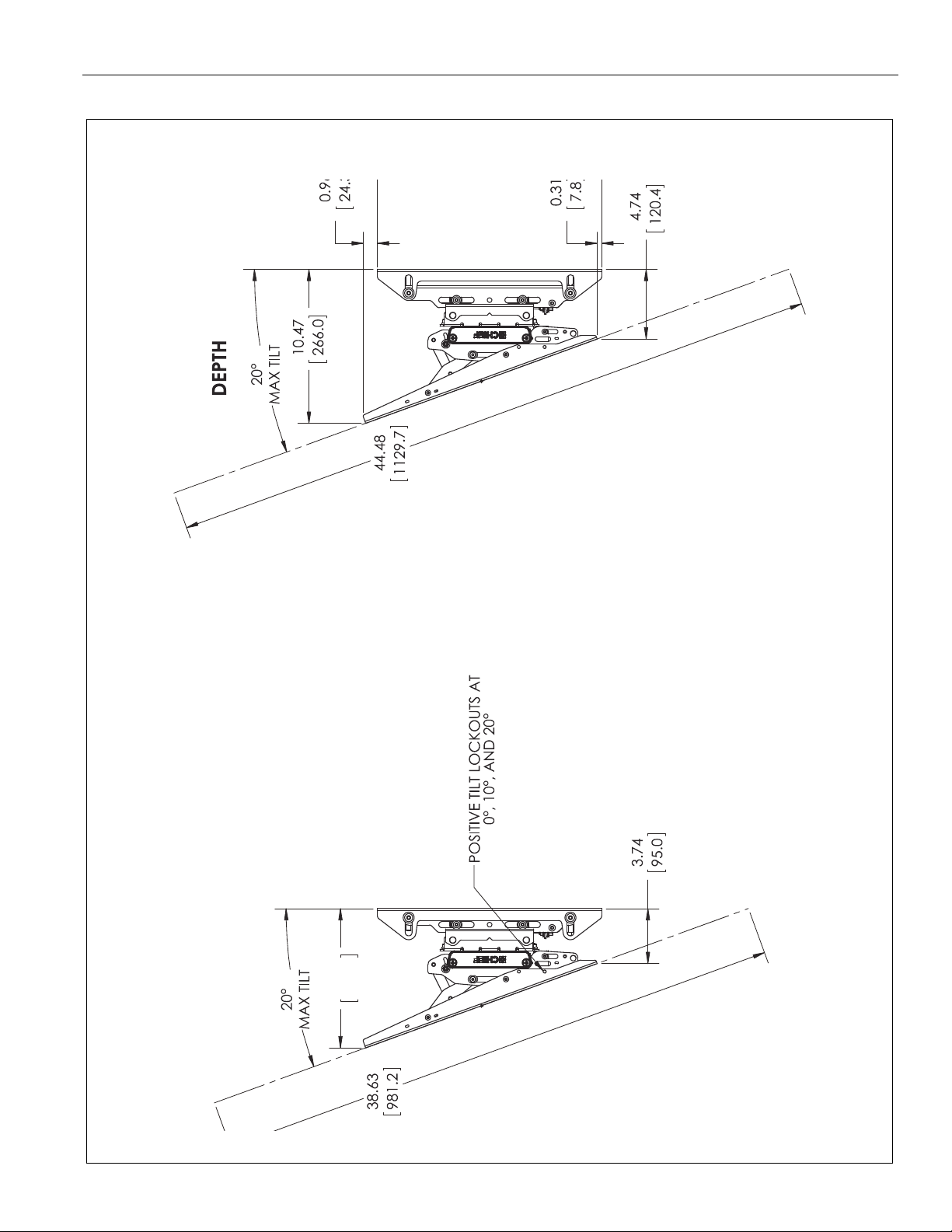
Page 19

Installation Instructions LWM Series
20°
MAX. TILT
9.47
240.6
MINIMUM
DEPTH
SHOWN WITH HEIGHT ADJUST
CENTERED
DIMENSIONS: INCHES
[MILLIMETERS]
LWM4X1U
DIMENSIONS (continued)
MAXIMUM
19
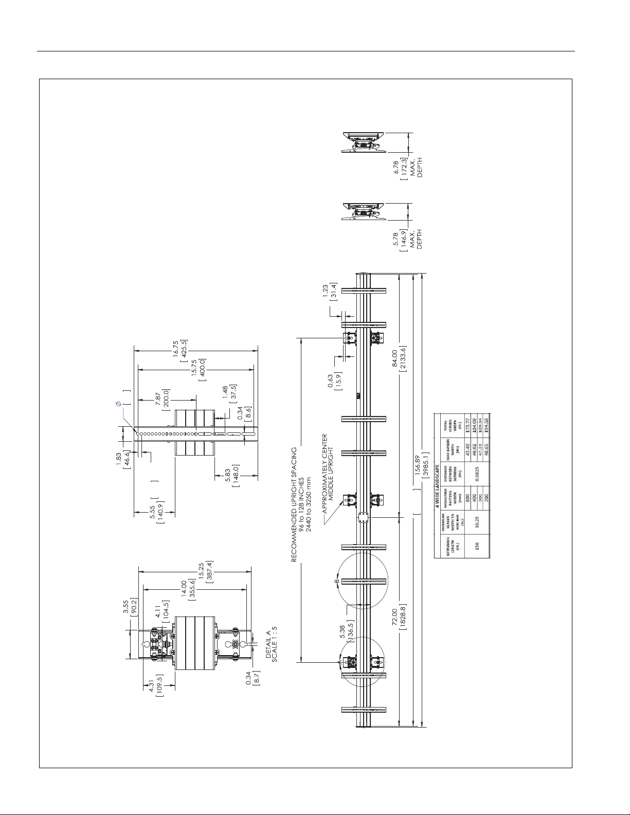
Page 20
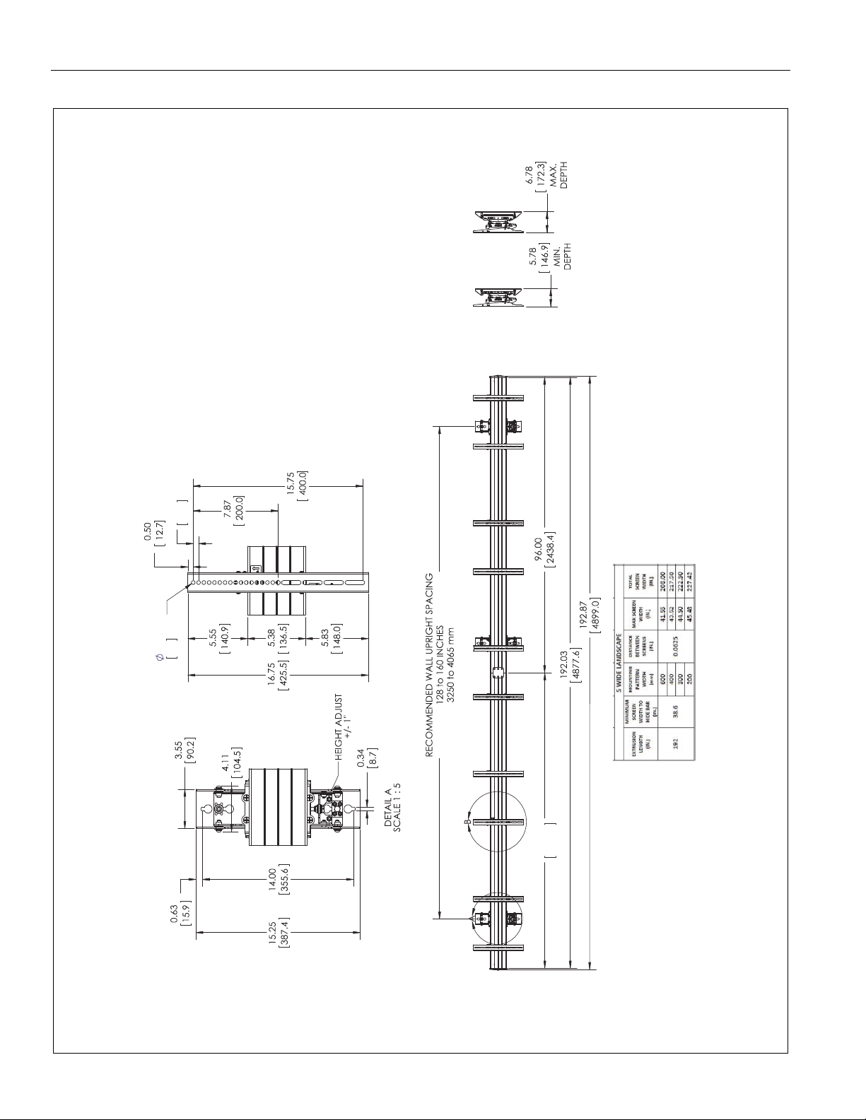
LWM Series Installation Instructions
96.00
2438.4
0.34
8.6
TYP.
0.49
12.5
DETAIL B
SCALE 1 : 5
LWM5X1U
DIMENSIONS: INCHES
[MILLIMETERS]
DIMENSIONS (continued)
TYP.
20
Page 21
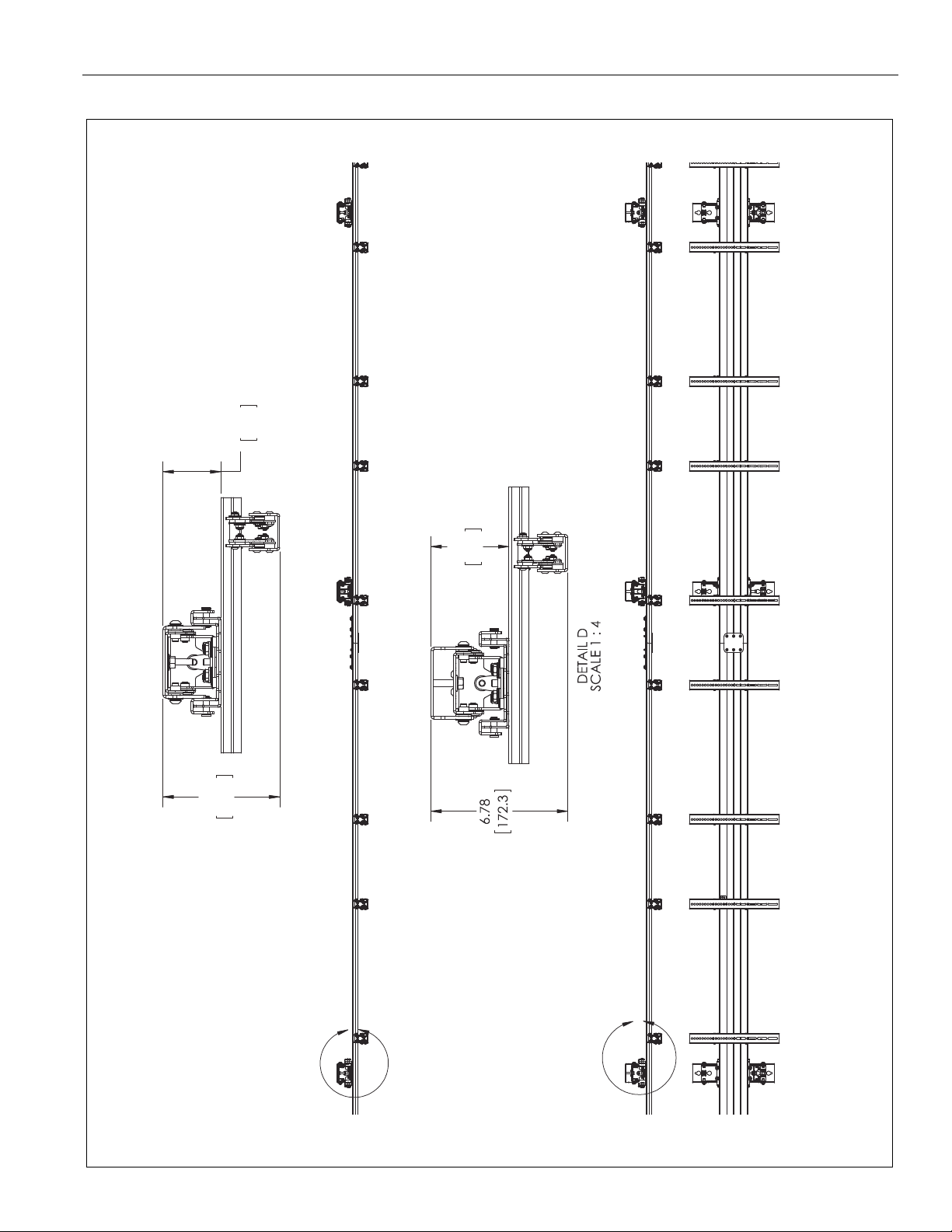
Installation Instructions LWM Series
D
C
2.87
72.9
5.78
146.9
DETAIL C
SCALE 1 : 4
3.87
98.3
DIMENSIONS: INCHES
[MILLIMETERS]
LWM5X1U
DIMENSIONS (continued)
21
Page 22

LWM Series Installation Instructions
3.74
95.0
DEPTH
DEPTH
LWM5X1U
DIMENSIONS: INCHES
[MILLIMETERS]
DIMENSIONS (continued)
MAXIMUM
22
MINIMUM
Page 23

Installation Instructions LWM Series
23
Page 24

LWM Series Installation Instructions
Chief, a products division of
Milestone AV Technologies
8800-002779 Rev01
2015 Milestone AV Technologies
www.chiefmfg.com
09/15
USA/International A 6436 City West Parkway, Eden Prairie, MN 55344
P 800.582.6480 / 952.225.6000
F 877.894.6918 / 952.894.6918
Europe A Franklinstraat 14, 6003 DK Weert, Netherlands
P +31 (0) 495 580 852
F +31 (0) 495 580 845
Asia Pacific A Office No. 918 on 9/F, Shatin Galleria
18-24 Shan Mei Street
Fotan, Shatin, Hong Kong
P 852 2145 4099
F 852 2145 4477
 Loading...