

Page 1
INSTALLATION INSTRUCTIONS
Small Flat Panel Mounts
Model: K-Series
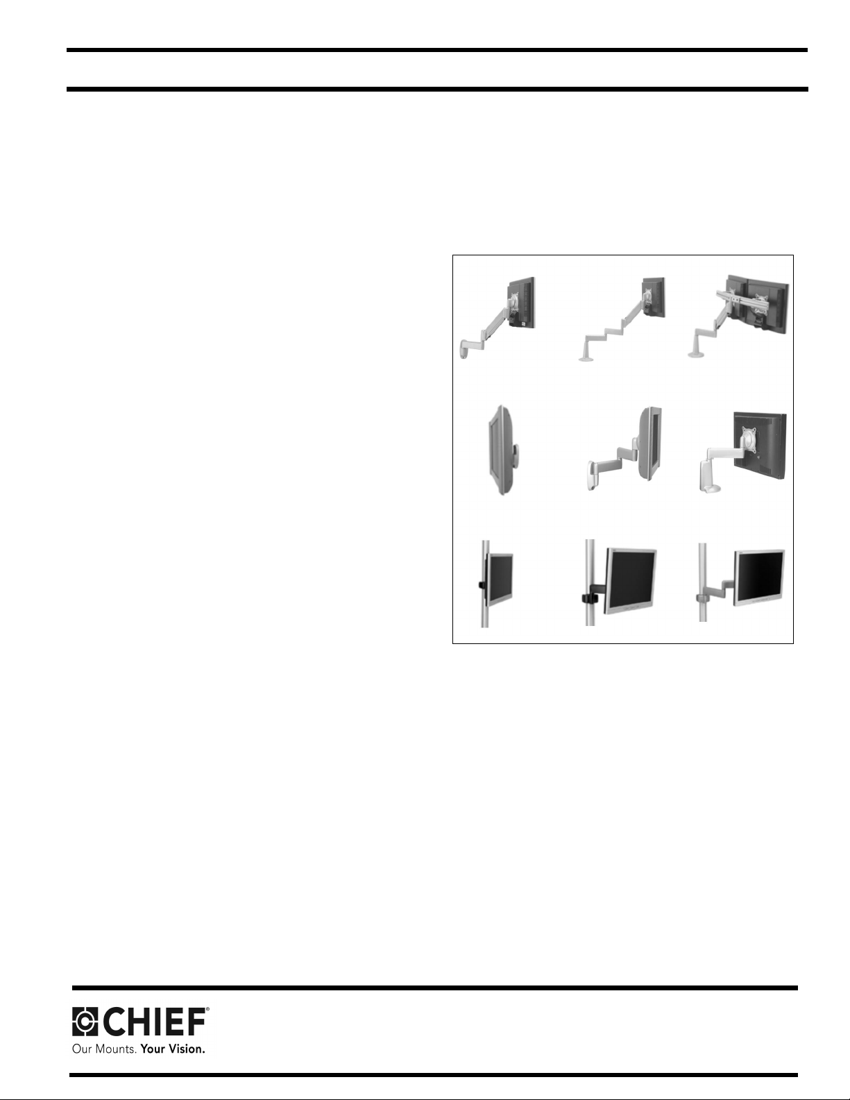
This Instruction Manual covers most of the K-Series wall,
desk, and pole mounts for single , dual, and triple
displays. In addition, this Instruction Manual also covers
selected K-Series accessories.
NOTE: Some K-Series moun ts, such as Extreme Tilt,
Grommet, and Table, as well as most K-Series
accessories, have separate Instruc tion Manuals.
See Specifications for a complete list of models
covered by this Instruction Manual.
NOTE: If an accessory such as an optional laptop tray is
being installed, complete all required installation
procedures within this document prior to installing
the accessory.
K-Series Mounts (Examples)
Chief, a products division of
Milestone AV Technologies
6436 City West Parkway, Eden Prairie, MN 55344
• P: 800.582.6480 / 952.225-6000 • F:877.894.6918 / 952.894.6918
8800-002338 Rev.01
©2016 Mileston e AV Technologies
www.milestone.com
08/16
Page 2
Model: K-Series Installation Instruc tions
DISCLAIMER
Milestone AV Technologies and its affiliated corporations and
subsidiaries (collectively "Milestone"), intend to make this
manual accurate and complete. However, Milestone makes no
claim that the information contained herein covers all details,
conditions or variations, nor does it provide for every possible
contingency in connection with the installation or use of this
product. The information contained in this document is subject
to change without notice or obligation of any kind. Milestone
makes no representation of warranty, expressed or implied,
regarding the in formation cont ai ned her ein. Mil estone assu mes
no responsibility for accuracy, completeness or sufficiency of
the information contained in this document.
Chief® is a regist ered t rademark of Mil estone AV Te chnologi es.
All rights reserved.
DEFINITIONS
MOUNTING SYSTEM: A MOUNTING SYSTEM is the
primary Chief product to which an accessory and/or compon ent
is attached.
ACCESSORY: AN ACCESSORY is the secondary Chief
product which is attached to a primary Chief product, and may
have a component attached or setting on it.
COMPONENT: A COMPONENT is an audiovisual item
designed to b e atta ched or rest ing o n an a ccessor y or mount ing
system such as a video camera, CPU, scree n, display,
projector, etc.
WARNING: Exceeding the weight capacity can result in
serious personal injury or damage to equipment! It is the
installer’s responsibility to make sure the combined we ight of
all components located between the K-Series mount up to
(and including) the display does not exceed the weight limit
listed in Table 1.
WARNING: Use this mounting system only for its intended
use as described in these instructions. Do not use
attachments not recommended by the manufacturer.
WARNING: Never operate this mounting system if it is
damaged. Return the mounting system to a ser vi ce center for
examination and repair.
WARNING: Do not use this product outdoors.
--SAVE THESE INSTRUCTIONS--
WARNING: A WARNING alerts you to the possibility of
serious injury or death if you do not follow the instructions.
CAUTION: A CAUTION alerts you to the possibility of
damage or destruction of equipment if you do not follow the
corresponding instructions.
IMPORTANT SAFETY INSTRUCTIONS
WARNING: Failure to read, thoroughly understand, and
follow all instructions can result in serious personal injury,
damage to equipment, or voiding of factory warranty! It is the
installer’s responsibility to make sure all mounting systems
are properly assembled and installed using the instructions
provided.
WARNING: Failure to pr ovide adequate structural strength
for this mounti ng systems can resul t in serious pe rsonal i njury
or damage to equipment! It is the installer’s responsibility to
make sure the structure to which this mounting system is
attached can support five times the combined weight of all
equipment. Reinforce the structure as required before
installing t he mounting systems. The wall to which the mou nt
is being attached may have a maximum drywall thickness of
5/8" (1.6cm). Do not install drywall anchors into the seam
between drywall pieces.
2
Page 3

Model: K-Series Installation Instruc tions
CONTENTS
TOOLS REQUIRED FOR INSTALLATION ...............................................................................................................3
SPECIFICATIONS.....................................................................................................................................................4
MOUNT INSTALLATION...........................................................................................................................................5
DISPLAY INSTALLAT ION...................... ................ ........................ ................. ................ ................. ................... ......8
ARRAY ASSEMBLY (DUAL / TRIPLE DISPLAY; ALL EXCEPT KCY-210/-220).....................................................10
MULTI-DUAL ARM ASSEMBLY (KCY-210/-220 ONLY)........................... .............................. ............................... ..1 1
CABLE MANAGEMENT..........................................................................................................................................12
ADJUSTMENT........................................................................................................................................................ 13
TOOLS REQUIRED FOR INSTALLATION
• Phillips Screwdriver, #1 and #2
• 9/16" Wrench (KSA-1015/-1016 Only), 7/16" Wrench (All Wall Mounts except KSA-1015/-1016)
• Drill (All Wall Moun ts)
• 1/8" Drill Bit (All Wall Mounts except KSA-1015/-1016)
• 1/4" Drill Bit (KSA-1015/-1016 Only)
• 2.5mm Hex Key (approximately 3/32"; provided with Desk Mounts)
• 5/32" Hex Key (provided with applicable K-Series mounts)
• 3/16" Hex Key (provided with all K-Series mounts)
NOTE: Other tools may be required depending on your method of installation.
3
Page 4
Installation Instructions Model: K-Series
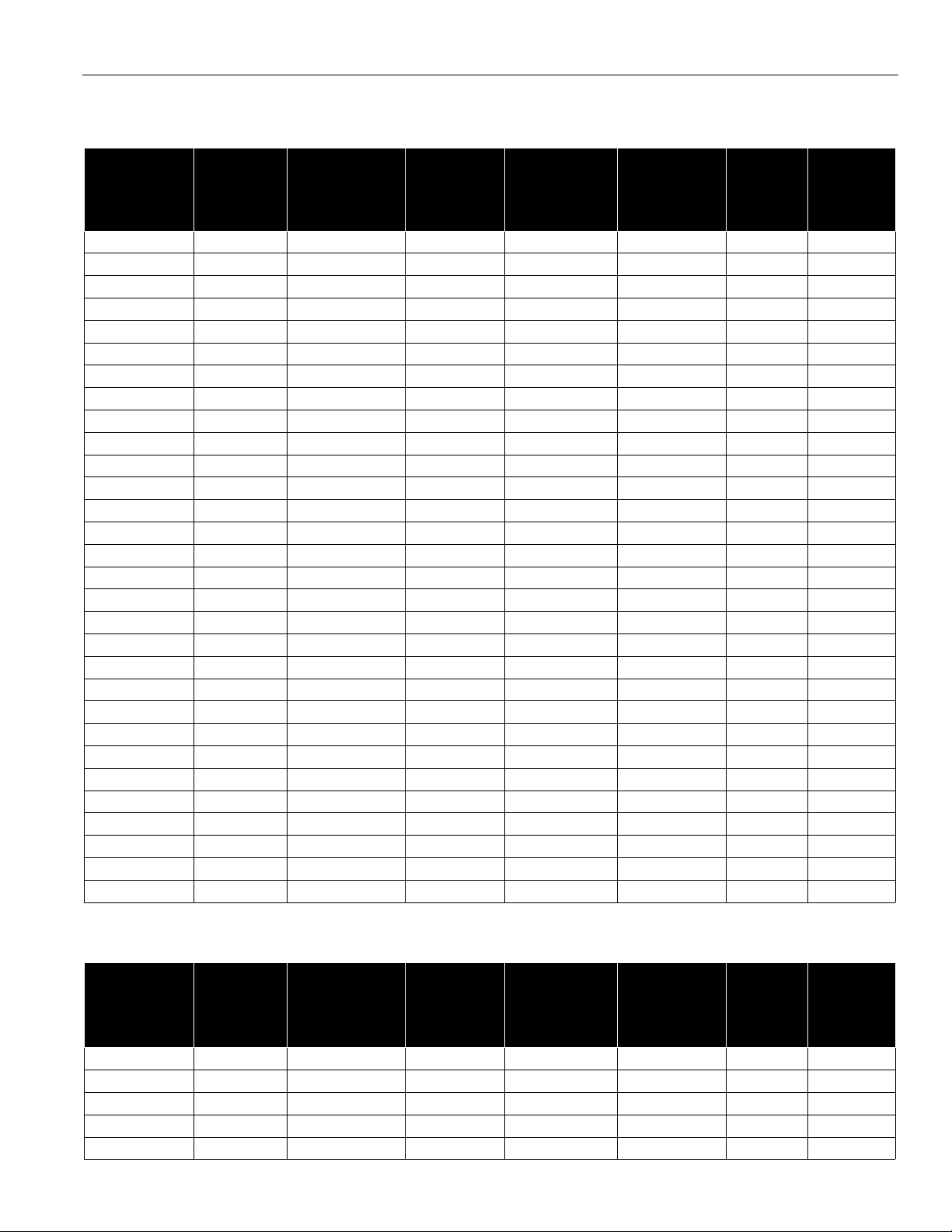
SPECIFICATIONS
Table 1: Mounts
MODEL NO. OF
DISPLAYS
SUPPORTING
STRUCTURE
NO. OF
MOUNTING
ARMS
ADJUSTABLE
HEIGHT
MAX.
EXTENSION
(INCHES)
MIN.
CLOSED
DEPTH
(INCHES)
KWP-110 Single Wall None No None 2.9 40
KWV-110 Single Wall Single Yes 13 2.2 25
KWS-110 Single Wall Single No 9.5 2.2 40
KWG-110 Single Wall Dual Yes 19.5 2.2 25
KWD-110 Single Wall Dual No 16 2.2 40
KWB-110 Single Wall Triple Yes 26 2.2 25
KCV-110 Single Desk Single Yes 13.5 2.2 25
KCS-110 Single Desk Single No 10 2.2 40
KCG-110 Single Desk Dual Yes 20 2.2 25
KCD-110 Single Desk Dual No 16.5 2.2 40
KCB-110 Single Desk Triple Yes 26.5 2.2 25
KPP-110 Single Pole None No None 2.2 40
KPS-110 Single Pole Single No 9.5 2.2 40
KPD-110 Single Pole Dual No 16 2.2 40
KPG-110 Single Pole Single Yes 16.5 2.2 25
KPV-110 Single Pole Single Yes 13.3 2.2 25
KWD-130 Single Wall Single Yes 18.6 5.1 25
KWS-220 Dual Wall Single No 13.5 6.4 17
KWD-220 Dual Wall Dual No 20 6.4 17
KCS-220 Dual Desk Single No 14 6.4 40
KCD-220 Dual Desk Dual No 20.5 6.4 17
KCY-210 Dual Desk Multi-Dual Yes (one arm) 20 2.2 20
KCY-220 Dual Desk Multi-Dual Yes (two arms) 20 2.2 20
KWD-230 Dual Wall Single No 18.6 5.9 40
KWS-320 Triple Wall Single No 13.5 6.4 10
KWD-320 Triple Wall Dual No 20 6.4 10
KCS-320 Triple Desk Single No 14 6.4 10
KCD-320 Triple Desk Dual No 20.5 6.4 10
KGL-110 Tray Desk Single Yes 29.5 14 18
KGL-220 Single/Tray Desk Dual Yes 29.5 14 40 total
MAX.
SUPPORT
WEIGHT
(LBS.)
PER MONITOR
Table 2: Accessories
MODEL NO. OF
MONITORS
SUPPORTING
STRUCTURE
NO. OF
MOUNTING
ARMS
ADJUSTABLE
HEIGHT
MAX.
EXTENSION
(INCHES)
MIN.
CLOSED
DEPTH
(INCHES)
KMA-220 Dual N/A N/A N/A N/A N/A 17
KMA-320 Triple N/A N/A N/A N/A N/A 10
KMA-325 Triple N/A N/A N/A N/A N/A 10
KSA-1015 N/A Wall Single No 16 6.4 75
KSA-1016 N/A Wall Dual No 24.5 6.4 75 total
MAX.
SUPPORT
WEIGHT
(LBS.)
PER MONITOR
4
Page 5
Installation Instructions Model: K-Series
MOUNT INSTALLATION
INSTALLATION TO WALL
1. Verify that you have the following parts:
Item Description Qty
10 MOUNT, Wall, K-Series 1
20 BRACKET, Wall 1
30 SCREW, Hex Head Lag, 1/4" x 2-1/2"
(ALL EXCEPT KSA-1 015/-1016)
40 SCREW, Hex Head Lag, 3/8" x 3"
(KSA-1015/-1016 ONLY)
50 WASHER, Flat Machine Sc rew, 1/4"
(ALL EXCEPT KSA-1 015/-1016)
2. Determine location for mount keeping in mind display
size, extension, height adjustment (if applicable), and
pitch/roll requirements. Bracket (20) MUST be
installed into wood stud.
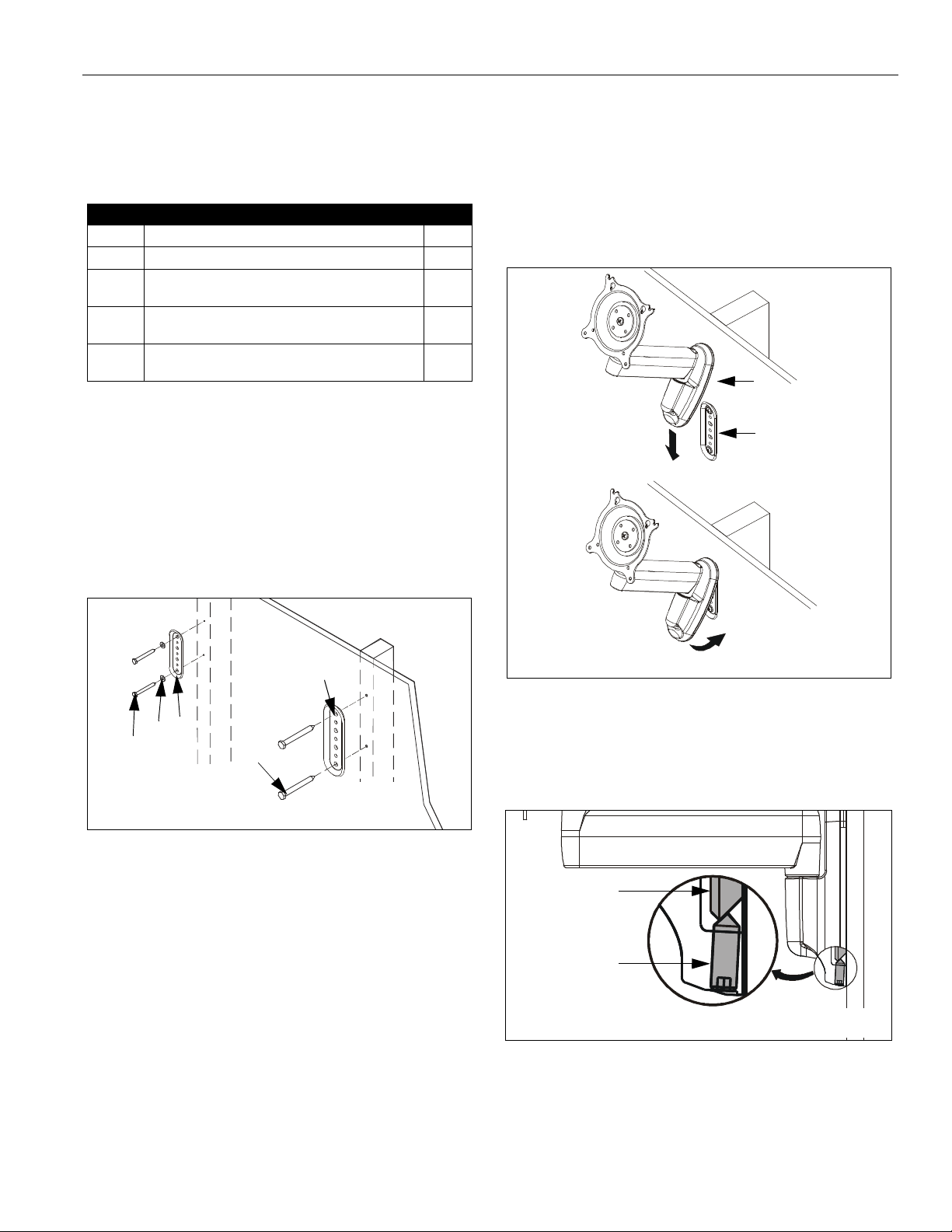
3. Using bracket (20) as a template, drill two pilot holes
through top and bottom holes of bracket (20) into wall
structure (See Figure 1):
• All Except KSA-1015/-1016: Use 1/8" drill bit
• KSA-1015/-1016 ONLY: Use 1/4" drill bit
2
2
2
IMPORTANT ! : IF you w ill be installing a SINGLE
display with RECESSED mounting holes, then proce ed
to "DISPLAY INSTALLATION" before continuing with this
mount installation procedure.
5. Insert top of mount (10) over lip on top of bracket (20)
(See Figure 2). Swing mount (10) down flush against
wall.
10
20
20
20
50
30
40
All except
KSA-1015/-1016
KSA-1015/-1016
Figure 1: Install Wall Bracket
4. Install bracket (20) (See Figure 1):
• All Except KSA-1015/-1016:
Using 7/16" wrench, install screws (30) through
washers (50), plate (20), and drywall into wood
stud. Ensure bracket (20) is vertical, then tighten
screws (30).
• KSA-1015/-1016 ONLY:
Using 9/16" wrench, install screws (40) through
plate (20) and drywall into wood stud. Tighten
screws (40).
IMPORTANT ! : Overtightening screws (30 or 40, as
applicable) may cause bracket (20) to compress into soft
wall surface, resulting in difficult mount installation or
improper engaging of set screw in step 6.
NOTE: KWS-110 shown; other wall mounts similar.
Figure 2: Install Wall Mount
6. Tighten set screw using 5/32" hex key (See Figure 3).
Ensure set screw engages back side of bracket (20)
to properly secure mount.
20
Set Screw
NOTE: KWS-110 shown; other wall mounts similar.
Figure 3: Tighten Set Screw
7. Proceed to "CABLE MANAGEMENT" (for SINGLE
display with RECESSED mounting holes), or to
"DISPLAY INSTALLATION" (for all other display
configurations).
5
Page 6
Model: K-Series Installation Instruc tions
INSTALLATION TO DESK
Two installation options exist:
• Edge Installation
• Hole (Grommet) Installation; requires 3/8" to 3"
diameter hole and access to the bottom of the
desk
ASSEMBLY
1. Verify that you have the following parts:
Item Description Qty
10 MOUNT, Desk, K-Series 1
20 BRACKET, Grommet 1
30 SCREW, Button Head Cap, 5/16"-18 x 4" 1
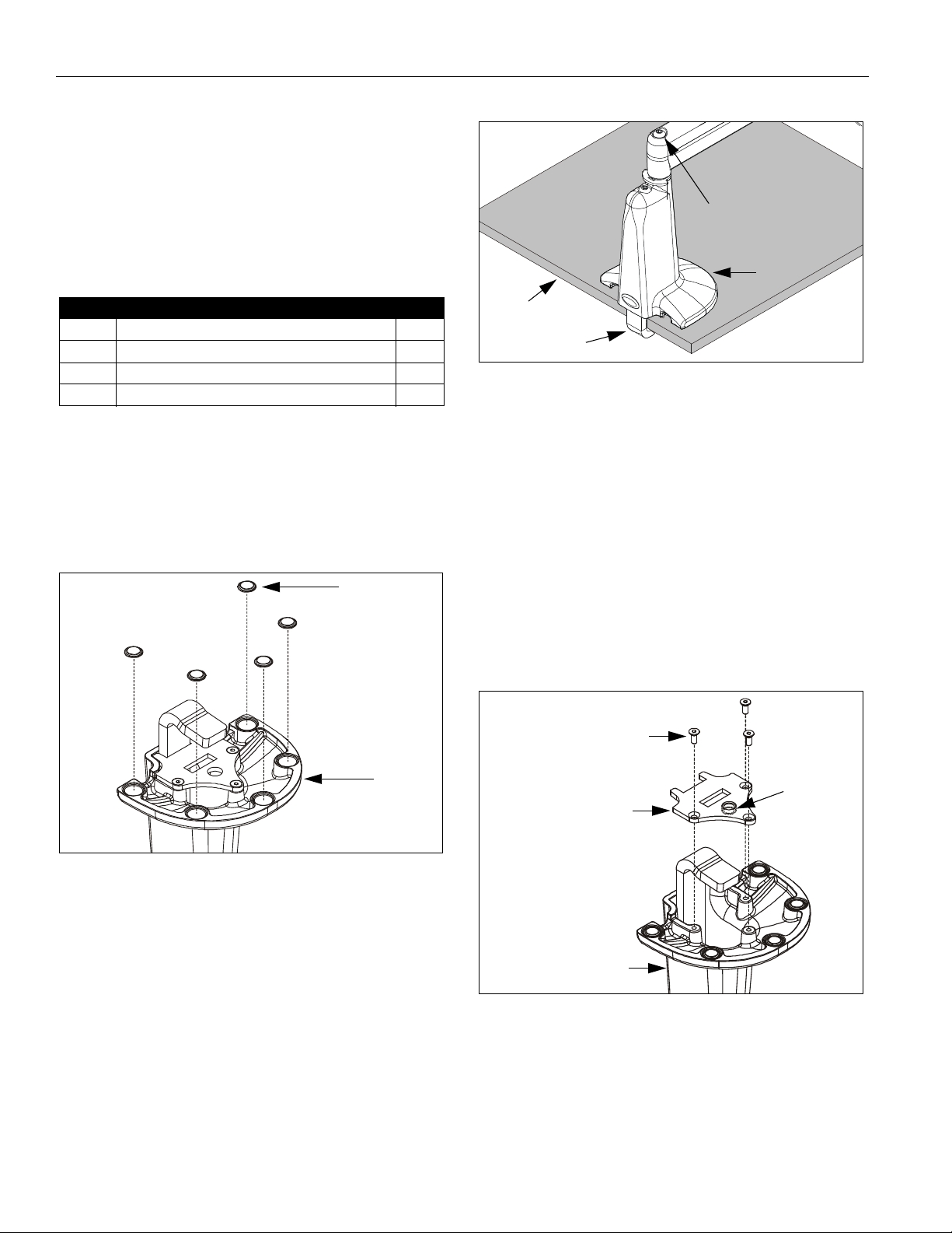
40 BUMPER, Adhesive 6
Edge
of Desk
Clamp
Figure 5: Desk Mount - Edge Installation
Clamp Adjustment
Screw
10
2. Determine approximate location for mount keeping in
mind display size, extension, height adjustment (if
applicable), and pitch/roll requirements.
3. Peel backing from adhesive bumpers (40) and attach
to bottom of mount (10) (See Fig ure 4).
NOTE: One extra bumper (40) included for convenience.
40
(5 places)
10
2. If you are installing:
• SINGLE display with RECESSED mounting
holes: Pro ceed to "CABLE MANAGEMENT."
• KCY-210/-220: Proceed to "MUL TI-DUAL ARM
ASSEMBLY."
• ALL other display configurations: Proceed to
"DISPLAY INSTALLATION."
HOLE (GROMME T) INSTALLATION
1. Using 2.5mm hex key, remove and retain baseplate
and three attach screws from bottom of mount (10)
(See Figure 6).
Attach Screws
(3 places)
Baseplate
Baseplate
Nut
Figure 4: Install Bumpers
EDGE INSTALLATION
IMPORTANT ! : IF you w ill be installing a SINGLE
display (including KCY-210/-220) with RECE SSED
mounting holes, then proceed to "DISPLAY
INSTALLATION" before continuing with this mount
installation procedure.
NOTE: Bracket (20) and screw (30) are not used in th is
installation.
1. Slip mount (10) over edge of desk so that clamp fully
contacts desk edge. Using 3/16" hex key, securely
tighten clamp adjustment screw (See Figure 5).
6
10
Figure 6: Baseplate
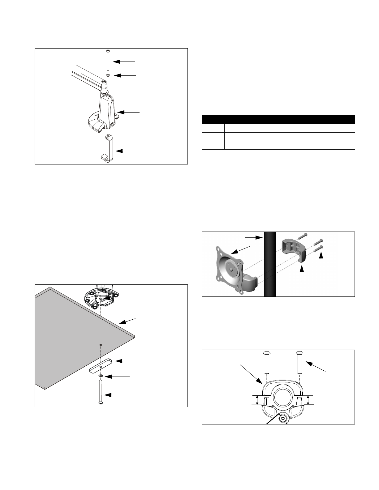
2. Using 3/16" hex key, remove clamp adjustment
screw, washer, and clamp (See Figure 7). Retain
clamp adjustment screw and washer for later use.
NOTE: Clamp will not be used for Hole (Grommet)
Installation.
Page 7
Installation Instructions Model: K-Series
Clamp Adjustment
7. If you are installing:
• SINGLE display with RECESSED mounting
holes: Pro ceed to "CABLE MANAGEMENT."
Screw
Washer
• KCY-210/-220: Proceed to "MUL TI-DUAL ARM
ASSEMBLY."
• ALL other display configurations: Proceed to
"DISPLAY INSTALLATION."
INSTALLATION TO POLE
10
Clamp
Figure 7: Remove Clamp Adjustme nt Screw
1. Verify that you have the following parts:
Item Description Qty
10 MOUNT, Pole, K-Series 1
20 CLA MP, Back 1
30 SCREW, Button Head Cap, 1/4"-20 x 1-1/4" 3
IMPORTANT ! : IF you w ill be installing a SINGLE
display with RECESSED mounting holes, then proce ed
to "DISPLAY INSTALLATION" before continuing with this
mount installation procedure.
3. Using 2.5mm hex key, re-install baseplate with three
retained attach screws. Ensure baseplate nut fac es
interior of mount (See Figure 6). Tighten securely.
IMPORTANT ! : IF you will be installing a SINGLE
display (including KCY-210/-220) with RECE SSED
mounting holes, then proceed to "DISPLAY
INSTALLATION" before continuing with this mount
installation procedure.
4. From below desk, insert retained clamp adjustment
screw and washer through bracket (20) and up
through hole in desk (See Figure 8 ). Using
3/16" hex key, thread screw into baseplate nut but do
not tighten completely at this time.
Baseplate Nut
Desk
20
2. Determine approximate location for mount keeping in
mind display size, extension, height adjustment (if
applicable), and pitch/roll requirements.
3. Place mount (10) against pole, with clamp (20) on
opposite side of pole (See Figure 9). Using 5/32" hex
key, loosely assemble with screws (30).
Pole
10
30
(3 places)
20
Figure 9: Pole Mount Installation
NOTE: Equally tighten screws (30) agains t mount and
the pole clamp (20). (See Figure 10)
4. Position mount at desired height and orientation.
Tighten screws (30) securely.
20
5. Center mount (10) over hole. Using 3/16" hex key,
securely tighten screw.
6. Drop screw (30) into open (unused) clamp adjustment
hole on top of mount (for appearance only).
Washer
Clamp Adjustment
Screw
Figure 8: Desk Mount - Hole Installation
30
(3 places)
Keep equal
distance between
mount and
clamp when
tightening
Figure 10: Securing Pole Mount and Clamp
5. Proceed to "CABLE MANAGEMENT" (for SINGLE
display with RECESSED mounting holes), or to
"DISPLAY INSTALLATION" (for all other display
configurations).
7
Page 8
Model: K-Series Installation Instruc tions
DISPLAY INSTALLATION
SINGLE D ISPLAY AND KCY-210/-220
NOTE: If you are installing DUAL / TRIPLE displays
(Except KCY-210/-220), then proceed to page 9.
The mounting holes on the back of your display will either
be flush with the back surface, or recessed into the back
surface. Refer to the applicable installation procedure.
FLUSH MOUNTING HOLES
1. Verify that you have the following parts:
Item Description Qty
10 MOUNT, K-Series 1
20 SCREW, Phillips Pan Machine, M4 x 12mm 4
CAUTION: Using screws of improper size may
damage your display! Proper screws will easily and
completely thread into display mounting holes.
CAUTION: Inadequate thread engagement in display
may cause display to fall! Back ou t screws ONLY as
necessary to allow installation of Centris b racket!
2. Ensure Centris bracket is able to swivel and tilt easily,
yet still be tight enough to hold display in desired
position. Adjust as required before proceeding. See
"ADJUSTMENT" for detail.
3. Using Phillips screwdriver, carefully install two screws
(20) into the upper mounting holes on the display.
Thread screws completely into display, then back out
3 complete turns.
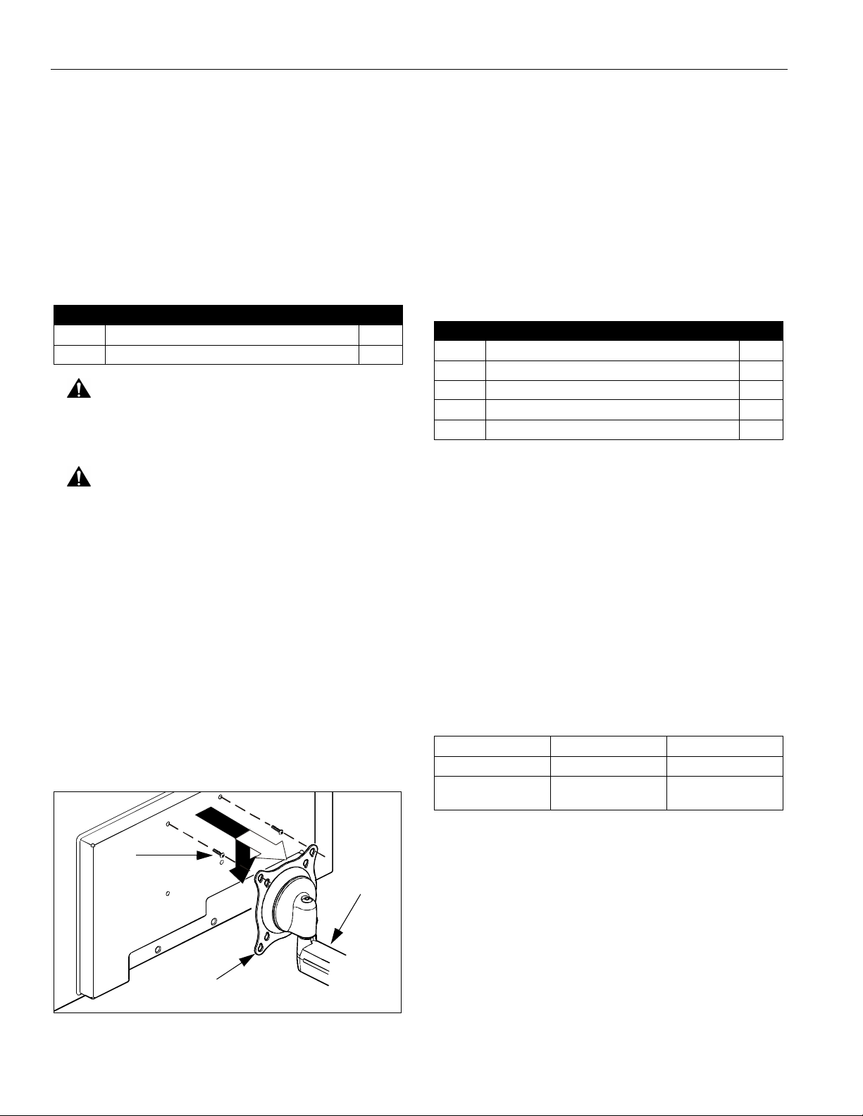
4. Pick up and align display so that screws (20) (installed
on the back of the display in the previous step) fit into
the mounting holes on the Centris bracket; rotate the
bracket as required (See Figure 11). Lower the
display firmly into place.
5. Using Phillips screwdriver, install two remaining
screws (20) through the lower mounting holes in
Centris bracket into the display.
6. Tighten all four screws (20). Do not overtighten!
7. KCY-210/-220 Only: Repeat Steps 1-6 for second
display.
8. Proceed to "CABLE MANAGEMENT."
RECESSED MOUNTING HOLES
1. Verify that you have the following parts:
Item Description Qty
10 MOUNT, K-Series 1
20 SCREW, Phillips Pan Machine, M4 x 20mm 4
30 SCREW, Phillips Pan Machine, M4 x 30mm 4
40 SPACER, Nylon, 3/8" long 4
50 SPACER, Nylon, 3/4" long 4
2. Ensure Centris bracket is able to swivel and tilt easily,
yet still be tight enough to hold display in desired
position. Adjust as required before proceeding. See
"ADJUSTMENT" for detail.
3. Carefully place display face down on protective
surface.
4. Determine depth of recessed mounting holes relative
to back surface of display (against which Centris head
will contact).
5. Select proper length spacer and screw from table
below:
NOTE: All spacers used should be the same length. If the
recess depths result in multiple spacer lengths,
then select the longer spacer.
IF recess DEPTH is: THEN use spacer: AND screw:
3/8" or less 40 (3/8" long) 20 (M4 x 20mm)
More than 3/8" up to
and including 3/4"
50 (3/4" long) 30 (M4 x 30mm)
6. Place the four selected spacers o ve r each of the
mount holes on the back of the display.
20
(2 places)
10
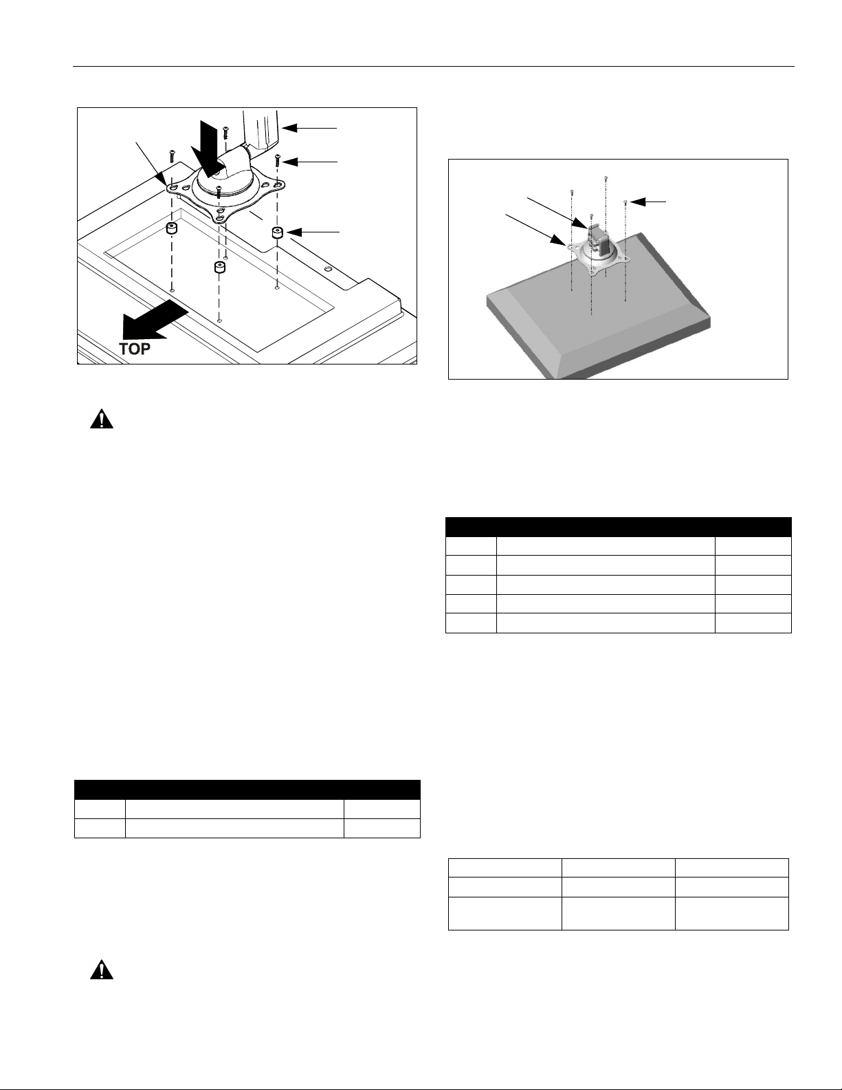
7. Pick up and orient the mount (10) so that the
mounting holes in the Centris bracket are aligned with
the holes in the spacers; rotate the bracket as
required (See Figure 12).
Centris Bracket
Figure 11: Single Display - Flush Mo unt
8
Page 9
Installation Instructions Model: K-Series
4. Using Phillips screwdriver, install four screws (20)
through the mounting holes in Centris bracket into the
Centris Bracket
10
20 or 30
(4 places)
40 or 50
(4 places)
display (See Figure 13). Tighten all four screws (20).
Do not overtighten!
10
Centris
20
(4 places)
Bracket
Figure 12: Single Display - Recessed Mount
CAUTION: Using screws of improper size may
damage your display! Proper screws will easily and
completely thread into display mounting holes.
8. Using Phillips screwdriver, install four selected
screws through the mounting holes in Centris bracket,
through the spacers, into the display (See Figure 12).
Tighten all four screws. Do not overtighten!
9. KCY-210/-220 Only: Repeat Steps 1-6 for second
display.
10. Continue with "MOUNT INSTALLATION."
DUAL / TRIPLE DISPLAY
(ALL EXCEPT KCY-210/-2 20)
The mounting holes on the rear of your display will either
be flush with the rear surface, or recessed into the rear
surface. Refer to the applicable installation procedure.
FLUSH MOUNTING HOLES
1. Verify that you have the following parts:
Item Descr iption Qty
10 CENTRIS HEAD, Dual Knob Assembly 2-3
20 SCREW, Phillips Pan Machine , M4 x 12mm 4 per head
Figure 13: Dual / Triple Display - Flush Mount
5. Proceed to "ARRAY ASSEMBLY."
RECESSED MOUNTING HOLES
1. Verify that you have the following parts:
Item Description Qty
10 CENTRIS HEAD, Dual Knob Assembly 2-3
20 SCREW, Phillips Pan Machine , M4 x 20mm 4 per head
30 SCREW, Phillips Pan Machine , M4 x 30mm 4 per head
40 SPACER, Nylon, 3/8" long 4 per head
50 SPACER, Nylon, 3/4" long 4 per head
2. Carefully place display face down on protective
surface.
3. Determine depth of recessed mounting holes relative
to back surface of display (against which Centris head
dual knob assembly will contact).
4. Select proper length spacer and screw from table
below:
NOTE: All spacers used should be the same length. If
the recess depths result in multiple spacer
lengths, then select the longer spacer.
2. Carefully place display face do wn on protective
surface.
3. Place the Centris head (dual knob assembly) onto the
back of the display, aligning the mounting holes on the
Centris bracket with the mounting holes on the
display.
CAUTION: Using screws of improper size may
damage your display! Proper screws will easily and
completely thread into display mounting holes.
IF recess DEPTH is: THEN use spacer: AND screw:
3/8" or less 40 (3/8" long) 20 (M4 x 20mm)
More than 3/8" up to
and including 3/4"
50 (3/4" long) 30 (M4 x 30mm)
5. Place the four selected spacers o ve r each of the
mount holes on the back of the display.
6. Place the Centris head (dual knob assembly) onto the
spacers, aligning the mounting holes on the Centris
bracket with the holes in the spacers (See Figure 14).
9
Page 10
Model: K-Series Installation Instruc tions
• KSA-1015/-1016 ONLY:
Insert large spacer (90), followed by large end of
pin (70) and small spacer (80).
20 or 30
(20 shown; 30 similar)
50
40
50
80
Centris
Bracket
10
20 or 30
(4 places)
40 or 50
(4 places)
Figure 14: Dual / Triple Display - Recessed Mount
CAUTION: Using screws of improper size may
damage your display! Proper screws will easily and
completely thread into display mounting holes.
7. Using Phillips screwdriver, install four selected
screws through the mounting holes in Centris bracket,
through the spacers, into the display (See Figure 14).
Tighten all four screws. Do not overtighten!
8. Proceed to "ARRAY ASSEMBLY."
ARRAY ASSEMBLY
(DUAL / TRIPLE DISPLAY;
ALL EXCEPT KCY-210/-220)
1. Verify that you have the following parts:
Item Description Qty
10 ARRAY 1
20 SCREW, Button Head Cap, 5/16"-18 x 4"
(Used for Pivot / Swing Arm)
30 SCREW, Button Head Cap, 5/16"-18 x 5"
(Used with Height Adjustable Arm)
40 WASHER, 5/16", UHMW (plastic) 1
50 WASHER, 5/16", Stainl ess Steel 2
60 PIN
(ALL EXCEPT KSA-1 015/-1016)
70 PIN
(KSA-1015/-1016 ONLY)
80 SPACER, UHMW (plastic) 1
90 SPACER, UHMW (plastic)
(KSA-1015/-1016 ONLY)
100 NUT, Nylock, 5/16"-18 1
110 SCREW, Button Head Cap,1/4"-20 x 1/2" 2
120 NUT, Square, Machine Screw, 1/4"-20 2
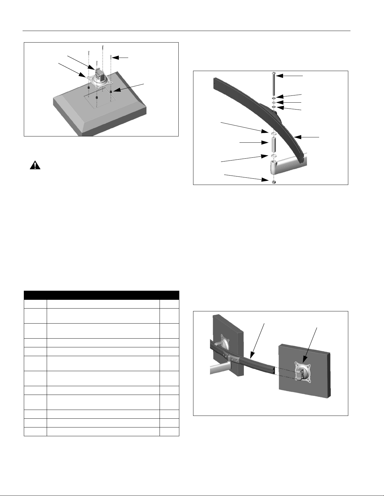
2. Install pin and spacer(s) into upper mount arm bore
(See Figure 15):
• All Except KSA-1015/-1016:
Insert pin (60) and spacer (80).
1
1
1
1
1
60 or 70
10
(60 shown; 70 similar)
90
100
Figure 15: Assemble Array
3. Install array (10) onto pin (60 or 70, as applicable)
(See Figure 15).
4. Insert and hold nut (100) into lower mount arm bore
(See Figure 15).
5. Insert screw (20 or 30, as applicable) through washer
(50), washer (40), washer (50), array (10), array/
mount arm assembly, and into nut (100) (See Figure
15). Tighten screw as required using 3/16" hex key.
6. Slide the Centris head (dual knob assembly) onto the
array (10) (See Figure 16). Ensure both the top and
the bottoms of the Centris head are engaged into the
corresponding slots in the array (10).
10
Centris Head
NOTE: Dual display shown ; triple display similar.
Figure 16: Install Display
7. Position the displays as desired and tighten the
Centris head knob closest to the array (10). See
"ADJUSTMENT" for additional information.
10
Page 11
Installation Instructions Model: K-Series
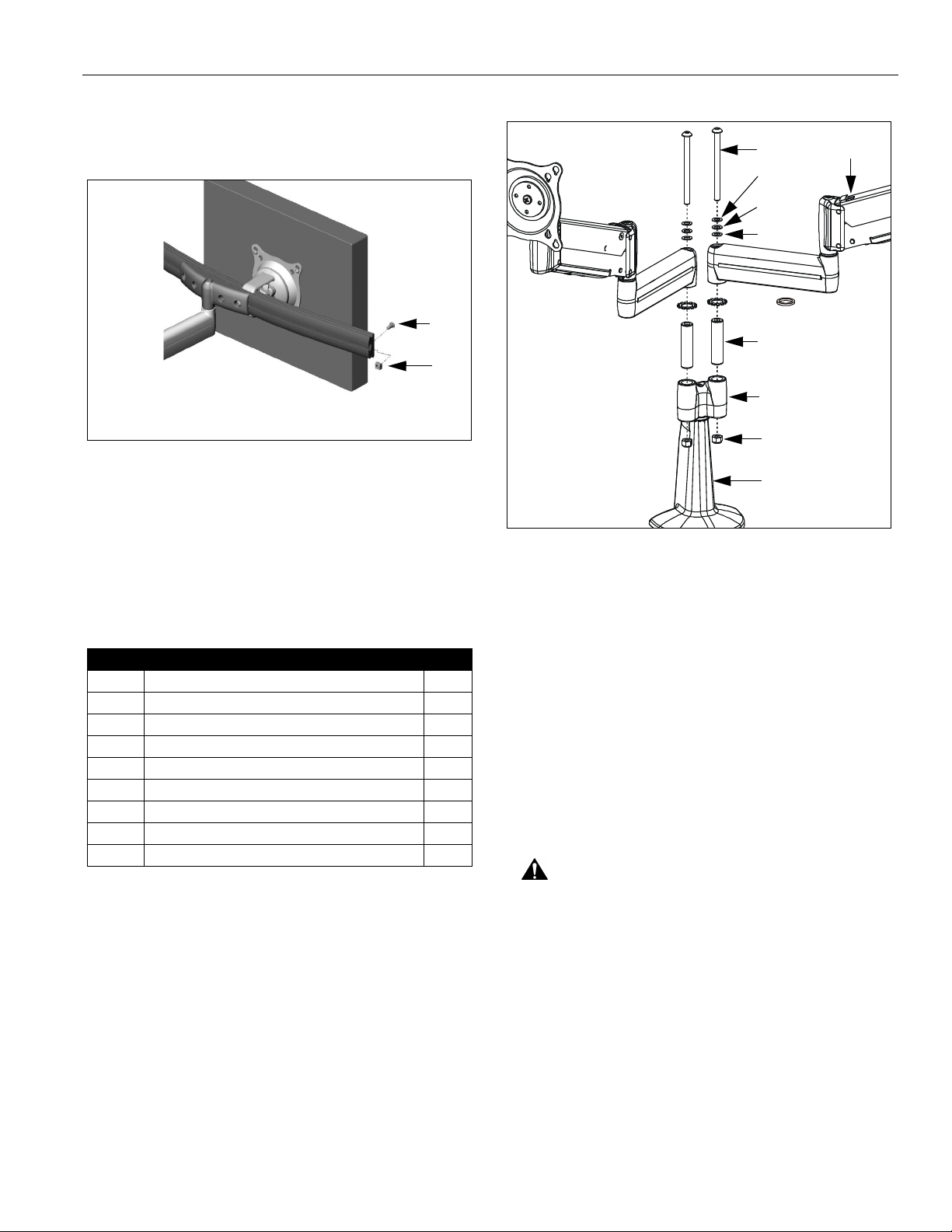
8. Using 5/32" hex key, install screw (1 10) and nut (120)
on each end of the array (10) to prevent displays from
accidently sliding off (See Figure 17).
50
40
50
80 or 70
110
60
120
Y-connector
1030
NOTE: Left side shown; right side similar
Figure 17: Install End Locks
9. Proceed to "CABLE MANAGEMENT."
MULTI-DUAL ARM ASSEMBLY
(KCY-210/-220 and FGL-220 ONLY)
BASIC ASSEMBLY
1. Verify that you have the following parts:
Item Description Qty
10 ARM ASSEMBLY, K-Series 2
20 MOUNT, Desk, K-Series 1
30 SCREW, Button Head Cap, 5/16"-18 x 4" 2
40 WASHER, 5/16", UHMW (plastic) 2
50 WASHER, 5/16", Stainl ess Steel 4
60 PIN 2
70 SPACER, UHMW (plastic) 2
80 WASHER, Lock, External Tooth, 5/8" 4
90 NUT, Nylock, 5/16"-18 2
NOTE: All p arts
same for both sides.
NOTE: KCY-220
90
20
shown; KCY-210
similar.
Figure 18: Multi-Dual Arm Assembly
3. Install spacer (70) or washer (80), as desired, on pin
(60) (See Figure 18).
NOTE: Spacer (70) will allow limited movement of arm
assembly (10) relative to Y-connector, dependent
upon tension of screw (30). Washer (80) will lock
arm assembly (10) to Y-connector. See
"ADJUSTMENT" for detail.
4. Insert arm assembly (10) on pin (60) (See Figure 18).
5. While holding nut (90) in lower bore of Y-connector,
insert screw (30) through washer (50), washer (40),
washer (50), arm assembly (10), and Y-connector,
into nut (90) (See Figure 18). Loosely install screw
(30) using 3/16" hex key.
2. Insert pin (60) into Y-connector upper bore in mount
(20) (See Figure 18).
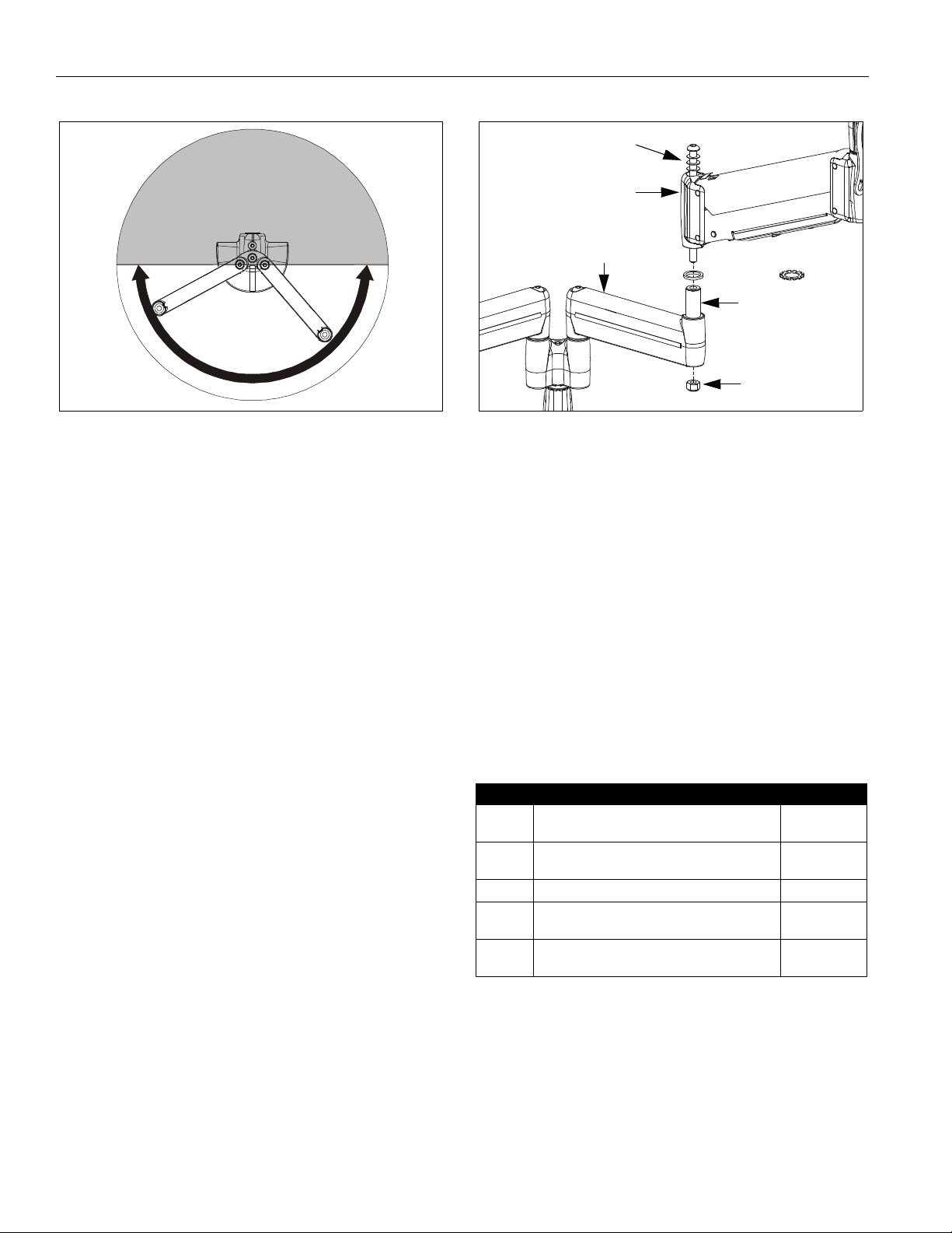
CAUTION: Improper positioning of arm assembly (10)
may result in failure of mount and subsequent damage
to displays. Do NOT position either arm assembly (10)
in gray shaded area.
6. Position arm assembly (10) within UNSHADED area
as shown (See Figure 1 9). Using 3/16" hex key,
tighten screw (30) as required to maintain position.
11
Page 12
Model: K-Series Installation Instruc tions
Screw & washers
DO NOT POSITION
EITHER ARM ASSEMBLY
IN GRAY SHADED AREA
ALLOWABLE
AREA
Outer arm
Inner arm
spacer or 80
pin
nut
Figure 19: Allowable Arm A rea
7. Repeat Steps 2. through 6. for second mount arm
assembly (10).
8. If desired, proceed to "MODIFICATION." Otherwise,
proceed to:
• "CABLE MANAGEMENT" (for display with
RECESSED mounting holes), or to
• "DISPLAY INSTALLATION" (for all other display
configurations).
MODIFICATION
If desired, each arm assembly (10) may be modified to
prevent movement of the outer arm relative to the inner
arm (without loosening the adjustment screw).
NOTE: Spacer (shipped configuration) will allow limited
movement of outer arm relative to inner arm,
dependent upon tension of screw. Washer (80)
will lock arms together. See "ADJUSTMENT" for
detail.
1. Using 3/16" hex key, loosen screw until nut can be
removed (See Figure 20). Retain nut. Screw and
washers may remain in outer arm.
Figure 20: Multi-Dual Arm Modification
2. Lift outer arm from pin (with screw and washers) and
place on protective surface.
3. Remove spacer from pin (See Figure 20).
4. Install washer (80) on pin (See F igure 20).
5. Re-install outer arm (with screw and washers) on pin
(See Figure 20).
6. Insert and hold nut in lower bore of inner ar m (See
Figure 20).
7. Tighten screw as required using 3/16" hex key (See
Figure 20).
8. Proceed to "CABLE MANAGEMENT" (for display with
RECESSED mounting holes), or to "DISPLAY
INSTALLATION" (for all other display configurations).
CABLE MANAGEMENT
Item Description Qty
10 COVER, Arm 1 per stati c
arm
20 SCREW, Phillips Flat Machine, 8-32 x 3/8" 2 per stati c
arm
30 WRENCH, Hex, 3/32" (provided) 1
40 CABLE TIE, (only provided with certain
models)
50 STRAIN RELIEF TIE (only provided with
certain models)
2 or 4
2 or 4
12
1. Attach all cables to display.
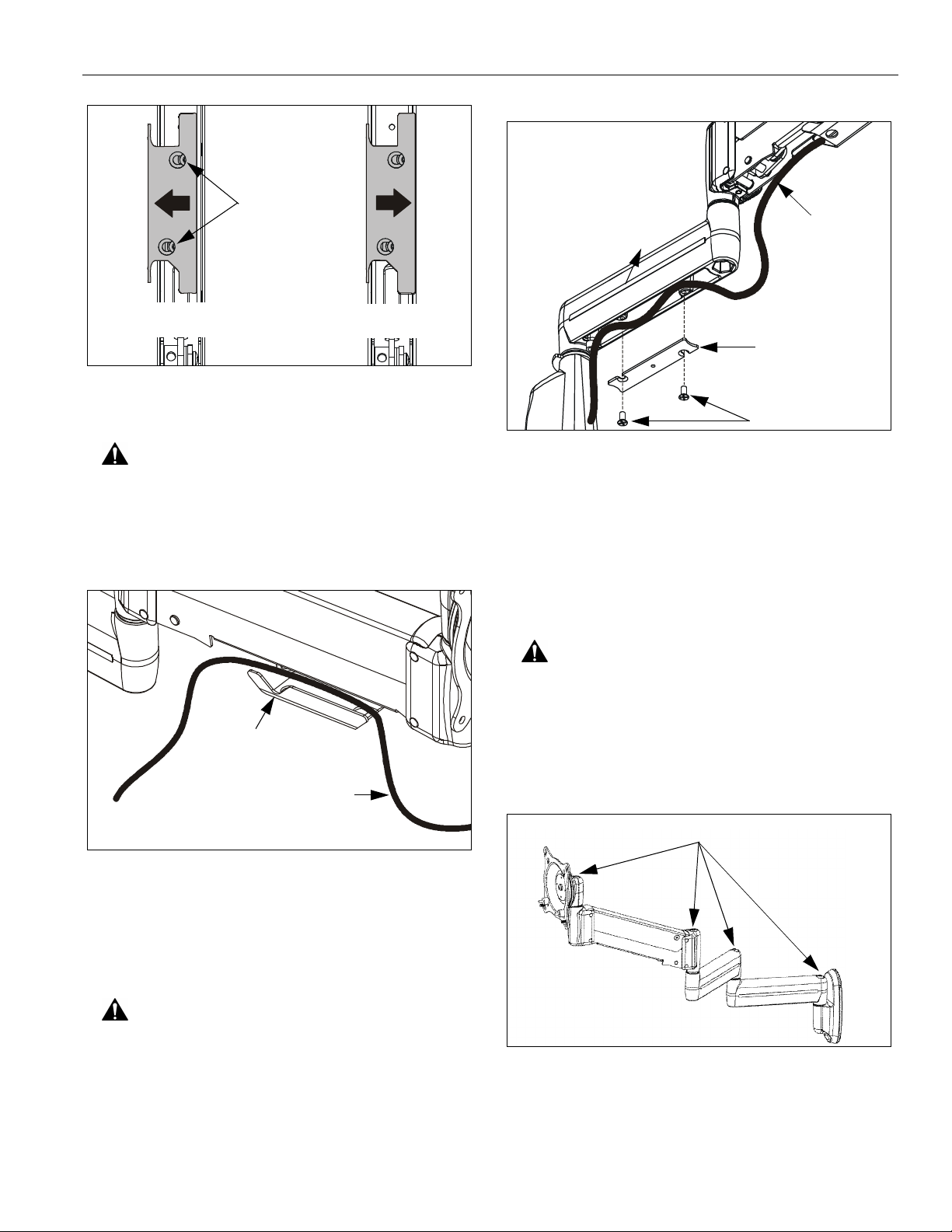
2. Open the cable management bracket (on heightadjustable arm only) by sliding it towards the edge of
the arm (See Figure 21).
NOTE: If necessary, cable management bracket attach
screws may be loosened using hex key (30).
Page 13
Installation Instructions Model: K-Series
Attach
OPEN Position
Screws
90
CLOSED Position
Cable Path
(typical)
View from Bottom
Figure 21: Height Adjustable Arm -
Cable Management Bracket
CAUTION: Ensure that adequate cable slack exists for
movement of display, and that cables will not be
pinched when bracket is closed.
3. Carefully insert cables into bracket (See Figure 22).
Cable Management
Bracket (in open position)
Cable Path (typical)
10
20
Figure 23: Static Arm - Cable P ath
NOTE: Installation is complete.
NOTE: Cable ties (provided with certain models) may be
used for additional cable management cap ability.
ADJUSTMENT
ARM
PIVOT / SWING
CAUTION: If washer (80) has been used to assemble
KCY-210/-220 arms, then forced movement of arms
without loosening screw (30) will damage arm and/or Yconnector (See Figure 18)(See Figure 20).
1. Using 3/16" hex key, slightly loosen or tighten the
adjustment screw(s) as necessary (See Figure 24) .
NOTE: Display not shown for clari ty.
Figure 22: Height Adjustable Arm - Cable Path
4. Close cable management bracket by sliding it back
towards the centerline of the arm (Se e Figure 21).
NOTE: If necessary, cable management bracket attach
screws may be tightened using hex key (30).
CAUTION: Ensure that adequate cable slack exists for
movement of display, and that cables will not be
pinched by installation of cover (10) or screw s (20).
5. Carefully insert cables in cavity located in lower
portion of static mount arm (See Figure 23).
6. Using Phillips screwdriver, install cover (10) with two
screws (20).
Adjustment Screws
Figure 24: Pivot / Swing Arm Adjustment
13
Page 14
Model: K-Series Installation Instruc tions
HEIGHT ADJUSTABLE (IF APPLICABLE)
IMPORTANT ! : It is important that the mount be
attached to the mounting surface AND display be
attached to the mount BEFORE attempting to adjust the
height adjustable arm.
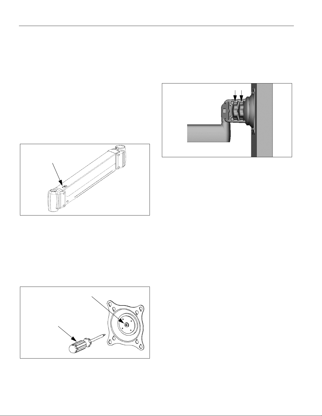
1. Using 5/32" hex key, slightly loosen or tighten the
adjustment screw as necessary (See Figure 25).
• If display settles on its own, then rotate
adjustment screw counterclockwise (towards the
"+" symbol).
• If display rises on its own, then rotate adjustment
screw clockwise (towards the "-" symbol).
NOTE: It may be necessary to raise or lower the height
adjustable arm to expose the adjustment screw.
Adjustment Screw
DUAL / TRIPLE DISPLAY
1. LATERAL POSITION ON ARRAY:
• Using your fingers, slightly loosen adjust ment
knob "A" (See Figure 27).
• Slide display to desired position.
• Using your fingers, tighten adjustment knob "A".
B
A
Figure 27: Dual / Triple Display Adjustment
2. PITCH / YAW / ROLL:
Figure 25: Height Adjustable A rm Adjustment
CENTRIS HEAD
SINGLE DISPLAY AND KCY-210/-220
1. If previously attached, disconnect cables from display ,
then remove display.
2. Using Phillips screwdriver, slightly loosen or tighten
the adjustment screw as necessary (See Figure 26).
Adjustment Screw
Phillips Screwdriver
• Using your fingers, slightly loosen adjust ment
knob "B" (See Figure 27).
• Adjust display as desired.
• Using your fingers, tighten adjustment knob "B".
Figure 26: Single Display Adjustment
3. Install mount and then display cables. See "DISPLAY
INSTALLATION."
14
Page 15

Installation Instructions Model: K-Series
15
Page 16

Model: K-Series Installation Instruc tions
16
 Loading...