

Page 1
INSTALLATION INSTRUCTIONS
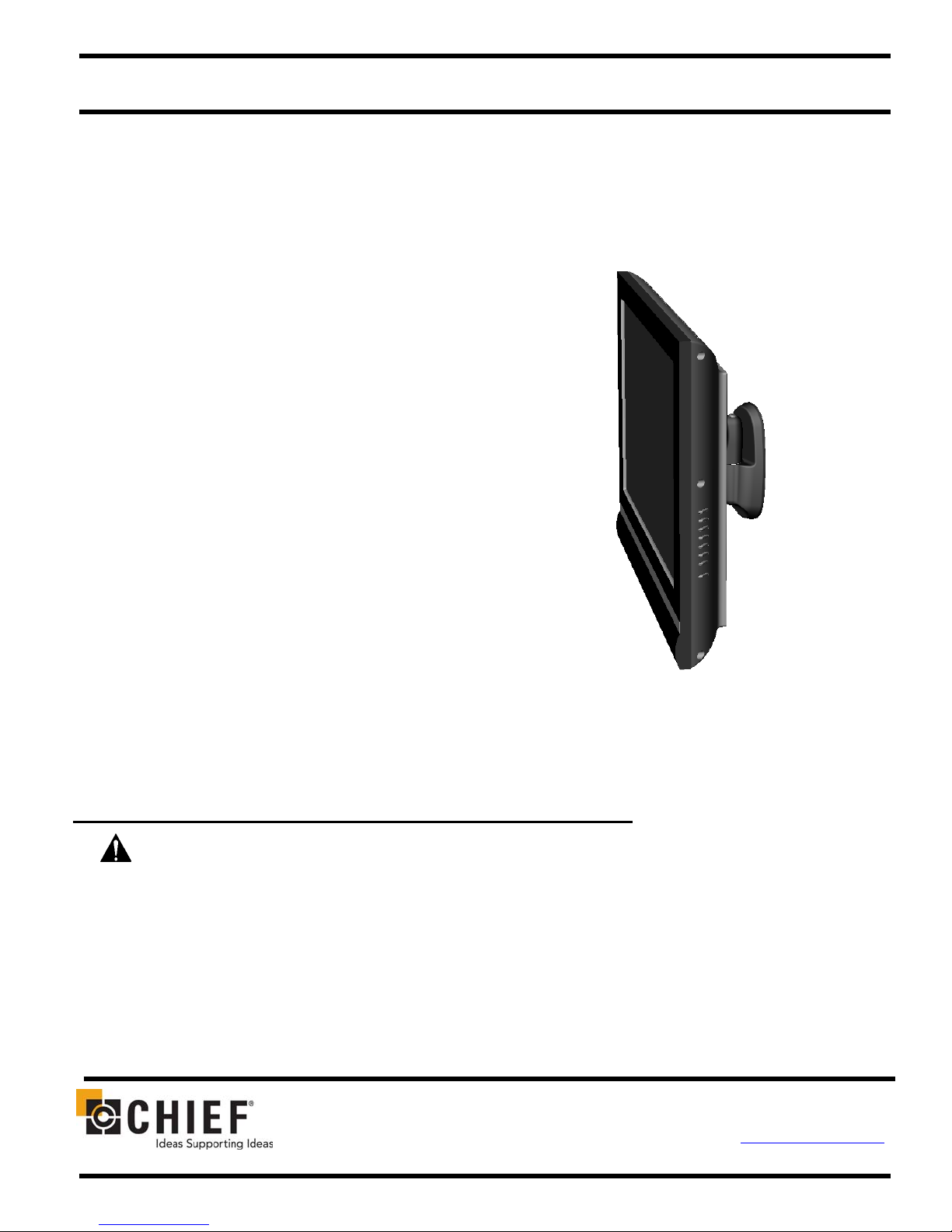
Medium Flat Panel
Pivot/Pitch Wall Mount
(JWP-210)
The JWP Pivot/Pitch wall mount is designed for mounting
a medium sized flat panel display. The mount can be
tilted up and down to 15° of center as well as pivot left
and right.
The JWP is shipped with the VESA
Centris™ interface which is compatible with most
medium flat panels.
To accommodate other mounting patterns in displays,
the JWP comes with a VESA Plate that accommodates
other VESA 200mm x 100mm and 200mm x 200mm
mounting patterns. This VESA Plate can also be used
with an MSB Custom Interface for non-VESA screens.
By design, the JWP can be configured to fit your medium
flat panel display, providing that your display does not
exceed the specified weight rating.
®
100mm/100mm
JWP-210
BEFORE YOU BEGIN
• CAUTION: To prevent damage to your display and/or the JWP, which could affect or void factory
warranty, thoroughly study all instructions and illustrations before you begin to install the mount. Pay
particular attention to ALL Warnings and Cautions in this document.
• The maximum weight allowable for use with the JWP wall mount is 75 lbs (34 kg).
• The JWP wall mount is designed to be installed using wall studs or supporting framework. The structure to which
the JWP wall mount is anchored must be capable of supporting five times the total weight of the mount and all
attached equipment.
• If you have any questions about this installation, contact Chief Manufacturing at 1-800-582-6480.
CHIEF MANUFACTURING INC. 8832-000074 (Rev. B)
1-800-582-6480 952-894-6280 FAX 952-894-6918 ©2005 Chief Manufacturing
8401 EAGLE CREEK PARKWAY, STE. 700 www.chiefmfg.com
SAVAGE, MINNESOTA 55378 USA 10/05
Page 2
Installation Instructions JWP-210
IMPORTANT WARNINGS and CAUTIONS!
WARNING
CAUTION
• WARNING
• WARNING
• WARNING
• WARNING
• WARNING
• WARNING
• CAUTION
A WARNING alerts you to the possibility of serious injury or death if you do not follow
the instructions.
A CAUTION alerts you to the possibility of damage or destruction of equipment if you
do not follow the corresponding instructions.
Improper installation can result in serious personal injury! Make sure that the structural
members can support a redundant weight factor five times the total weight of the
equipment. If not, reinforce the structure before installing the mount.
Be aware of the potential for personal injury or damage to the equipment if it is not
adequately mounted.
The installer is responsible for verifying that the display to which the JWP mount is
anchored will safely support the combined load of all attached components or other
equipment.
The weight of the display placed on the JWP must not exceed 75 lbs (34 kg), the
maximum support weight of the JWP.
Watch for pinch points. Do not put your fingers between movable parts.
Make sure the mount and brackets are correctly oriented.
Check the unit for shipping damage before you begin the installation.
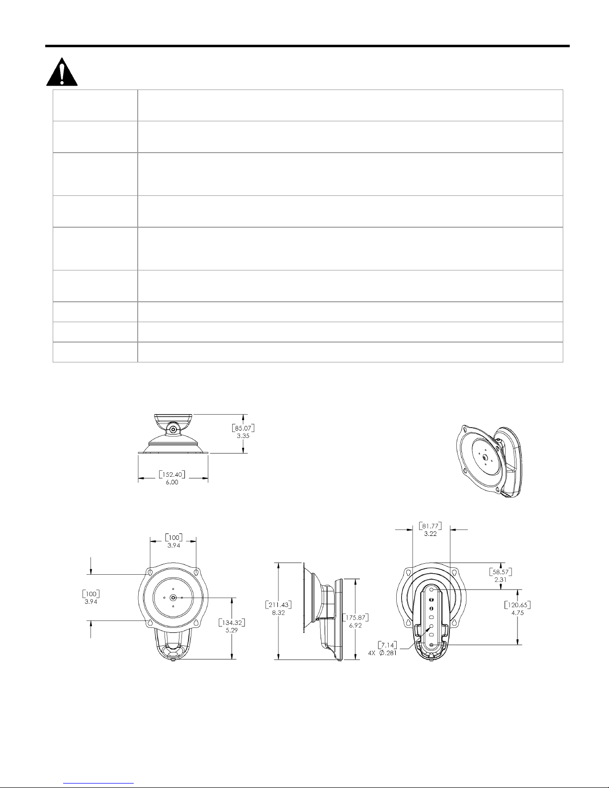
DIMENSIONAL DRAWING
2
Page 3
Installation Instructions JWP-210
CONTENTS
DIMENSIONAL DRAWING........................................2
TOOLS REQUIRED FOR INSTALLATION .............3
INSPECT UNIT BEFORE INSTALLING ..................3
SPECIFICATIONS ......................................................3
INTRODUCTION .........................................................4
Reference Chart.......................................................4
Mounting-Hole Configurations ...............................4
COMPONENTS ...........................................................5
PARTS ..........................................................................6
SECURE WALL BRACKET .......................................7
INSTALLATION (100mm x 100mm).........................7
Flush Mount Centris Bracket to Display...............7
Recess Mount Centris Bracket to Display ...........8
INSTALLATION (200mm x 100mm)........................8
Attach VESA Plate to Display ................................8
Attach Display to Centris Bracket..........................8
INSTALLATION (200mm x 200mm).........................9
Attach VESA Plate to Display ................................9
Attach Display to Centris Bracket..........................9
INSTALLATION (MSB CUSTOM INTERFACE).....10
Attach Display to Centris Bracket..........................10
ATTACH MOUNT TO WALL BRACKET .................11
CABLE MANAGEMENT.............................................12
ADJUST LATERAL TENSION ..................................12
ADJUST PITCH TENSION ........................................12
TOOLS REQUIRED FOR
INSTALLATION
• Electric drill and bit set
• Hex wrench set
• Phillips screwdriver
• Level
NOTE: Other tools may be required depending on your
display, JWP configuration and method of
installation.
INSPECT UNIT BEFORE
INSTALLING
WARNING: Watch for pinch points. Do not put
your fingers between movable parts.
1. Carefully inspect mount for shipping damage. If any
damage is apparent, call your carrier claims agent
and do not continue with installation until carrier has
reviewed damage.
NOTE: Read all instructions before starting
installation.
2. Lay out components to ensure you have all required
parts before proceeding (see PARTS on page 6). If
you are missing any listed parts, contact Customer
Service at: 1-800/582-6480.
SPECIFICATIONS
Table 1. JWP Specifications
Depth from
Wall 3.35” (85.07mm)
Maximum
Extension Not Applicable
Dimensions
W x H x D
Weight
Capacity
6.0” x 8.32” x 3.35”
(152 x 211.43 x 85.07mm)
75 lbs (34kg)
3
Page 4
Installation Instructions JWP-210
INTRODUCTION
There are three main steps in the JWP-210
installation process. These steps are:
• Selecting an appropriate mounting configuration.
• Connect display cables
• Making required adjustments
Before starting the installation process, determine the
correct mounting-hole configuration for your display by
reviewing the information located within Table 2.
NOTE: If the displays mounting hole configuration does
not match those identified at right, a custom MSB
interface is required. Refer to a Chief Mfg. crossreference or visit
the appropriate MSB for your display.
www.chiefmfg.com to identify
Reference Chart
Table 2 below provides a reference chart to help you
determine the mounting-hole configuration of your display
and quickly find the appropriate installation instructions.
Table 2. Installation Reference Chart
Screw Size
M4 x 12mm
M4 x 20mm
M4 x 16mm 200mm x 100mm 8
M4 x 20mm
M6 x 20mm
M6 x 30mm
OR
M6 x45mm
N/A
VESA Hole Pattern
100mm x 100mm
(Flush Mount)
100mm x 100mm
(Recess Mount)
200mm x 200mm 10
Non-VESA
(used with MSB Custom
Interface bracket, purchased
separately)
Ref.
Page
7
7
11
Mounting-Hole Configurations
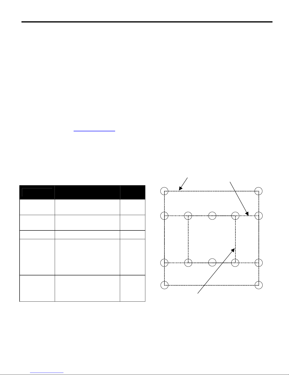
Figure 1 depicts the various mounting-hole configurations
that are available to mount your display.
200mm x 200mm
200mm x 100mm
100mm x 100mm
Figure 1. Typical VESA Mounting Hole Configurations
4
Page 5
Installation Instructions JWP-210
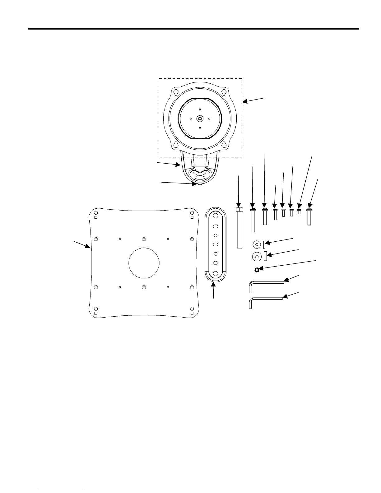
COMPONENTS
Figure 2 shows the parts and parts bags shipped with JWP.
Centris Bracket
(See notes)
20
Set Screw (see
10
30
Figure 2. JWP Components
40
110
100
50
60
70
90
80
120
130
140
150
160
5
Page 6
Installation Instructions JWP-210
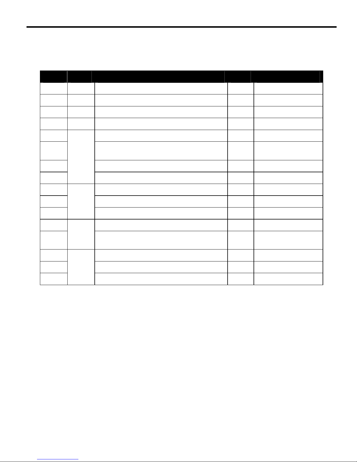
PARTS
Table 3 provides a list of the individual part and parts bags shipped with JWP parts.
Table 3. JWP Parts List
Item Bag Description Qty Notes
10 10 JWP MOUNT 1 See page 5 for graphic.
20 — Interface Adapter 1 Use with 50
30 — Wall Bracket 1 Use with 40
40 — Lag Screws, 3/8” x 3” 2 Use with 30
50 Phillips Pan Head Machine Screw, M4 X 8mm 4 Use with 20
60
A
70 Phillips Flat Head Machine Screw, M4 X 16mm 6 Use with 120
80
90 Phillips Pan Head Machine Screw, M6 X 20mm 4 Use with 130
100 Phillips Pan Head Machine Screw, M6 X 30mm 4 Use with 130
110
120 Nylon Spacer, 1/8” 6 Use with 70
130
140 Nylock Nut, 10-24 4 Use with MSB
150 Hex Key, 5/32” 1 For Set Screw
160
B
C
D
Phillips Pan Head Machine Screw, M4 X 12mm 4
Phillips Pan Head Machine Screw, M4 X 20mm 4 Use with 130
Phillips Pan Head Machine Screw, M6 X 45mm 4 Use with 130
Nylon Spacer, 1/4” 4
Hex Key, 3/16” 1 For Tension Adjust.
[Color Black] Use with
Centris Interface
Use with 80, 90, 100
and 110
6
Page 7
Installation Instructions JWP-210
SECURE WALL BRACKET
WARNING: It is the responsibility of the
installer to verify that the surface to which the mount
is anchored will safely support the combined load of
all attached components and equipment.
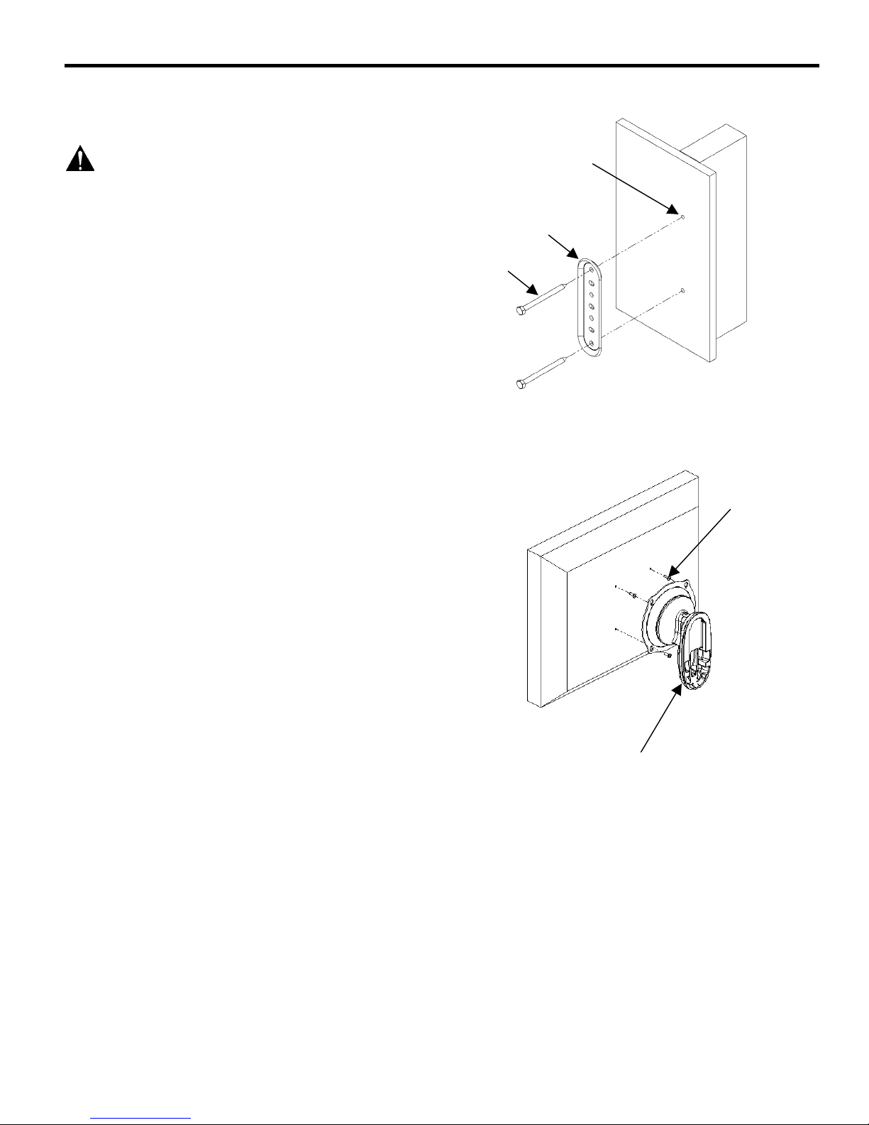
Install wall bracket as follows:
1. Determine exact mounting location prior to
installation, considering unit’s swing arm and
extension radius.
2. Using wall bracket (30) as a template, mark two pilot
holes. (See Figure 3).
3. Drill two ¼” pilot holes a minimum depth of 2” into
wood stud.
NOTE: Make sure wall bracket is level before installing
lag bolts.
4. Using a 9/16” socket wrench, install two lag bolts (40)
to wall. Do not over-tighten the lag bolts.
INSTALLATION
(100mm x 100mm)
Flush Mount Centris Bracket to Display
Pilot Holes
30
40
Figure 3. Secure Wall Bracket
80
To flush mount Centris Bracket:
1. Start two M4 x 12mm screws (80) into top mounting
holes (not shown) on display.
2. Align mounting holes on Centris Bracket with screws
installed on display. Hang display on Centris Bracket
(see Figure 4).
3. Install two remaining M4 x 12mm screws (80) into
bottom mounting holes on display.
4. Tighten screws.
5. Proceed to “ATTACH MOUNT TO WALL BRACKET”
on page 11.
Centris Bracket
Figure 4. Flush Mount Centris Bracket to Display
7
Page 8
Installation Instructions JWP-210
y
y
Recess Mount Centris Bracket to Display
To recess mount Centris bracket:
1. Lay display down on a flat surface.
80
CAUTION: Make sure surface is clean and
free of dirt and debris before laying display down.
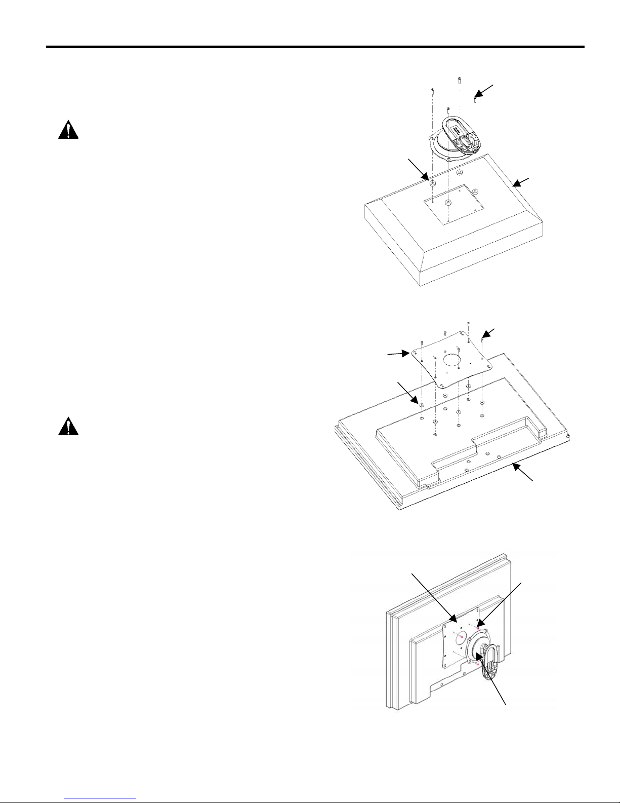
2. Select four screws M4 x 20mm screws (80) and four
spacers (130) from parts bag.
3. Place four spacers (130) over mounting holes on
back of display (see Figure 5).
4. Align mounting holes on Centris bracket with spacers
installed on display.
5. Install four screws M4 x 20mm screws (80) to attach
Centris bracket to display.
130
Displa
6. Tighten screws.
7. Refer to “ATTACH MOUNT TO WALL BRACKET”
section on page 11.
INSTALLATION
(200mm x 100mm)
Attach VESA Plate to Display
1. Lay display face down on a flat surface.
CAUTION: Make sure surface is clean and
free of dirt and debris before laying display down.
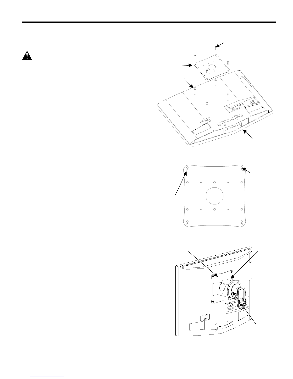
2. Place six spacers (120) over six mounting holes in
display as shown in Figure 6.
3. Attach VESA Plate (20) to display using six
M4 x 16mm flat head screws (70).
4. Tighten screws.
Attach Display to Centris Bracket
1. Start two M4 x 8mm Phillips pan head screws (50)
into top mounting holes on VESA Plate (20).
2. Align mounting holes on Centris bracket with screws
installed in Step 1 (see Figure 7).
Figure 5. Recess Mount Centris Bracket to Display
70
20
120
Displa
Figure 6. Attach Interface Bracket to Display
(200mm x 100mm)
20
50
3. Install remaining two M4 x 8mm Phillips pan head
screws (50) into bottom mounting holes of VESA
Plate (20).
4. Tighten screws.
5. Proceed to “ATTACH MOUNT TO WALL BRACKET”
section on page 11.
8
Centris Bracket
Figure 7. Attach Display to Centris Bracket
Page 9
Installation Instructions JWP-210
y
INSTALLATION
(200mm x 200mm)
80,90, 100 or 110
WARNING: It is the responsibility of the
installer to use the correct diameter and length of
fastener to attach interface to back of display.
Failure to do so may cause damage to the display or
personal injury.
20
130
Attach VESA Plate to Display
1. Lay display face down on a flat surface.
NOTE: Make sure surface is clean and free of dirt and
debris before laying display down.
2. Place four spacers (130) over four mounting holes in
display as shown in Figure 8.
3. Depending on mounting hole size and depth, attach
VESA Plate (20) by selecting applicable screws size,
as follows (see Figure 9):
a. Use four M4 x 20mm pan head screws (80) and
square holes to attach VESA Plate (20). Or,
b. Use four M6 x 20mm pan head screws (90) and
round holes to attach VESA Plate (20). Or,
c. Use four M6 x 30mm pan head screws (100) and
round holes to attach VESA Plate (20). Or,
d. Use four M6 x 45mm pan head screws (110) and
round holes to attach VESA Plate (20).
4. Tighten screws.
Attach Display to Centris Bracket
1. Start two M4 x 8mm Phillips pan head screws (50)
into top mounting holes on VESA Plate (20). See
Figure 10.
2. Align mounting holes on Centris bracket with screws
installed in Step 1.
3. Install two remaining M4 x 8mm Phillips pan head
screws (50) through bottom mounting holes of
Centris bracket, and into VESA Plate (20).
Figure 8. Attach Interface Bracket to Display
M4 Screws
Figure 9. VESA Plate Mounting Holes
20
Displa
M6 Screws
50
4. Tighten screws.
5. Proceed to “ATTACH MOUNT TO WALL BRACKET”
section on page 11.
Centris
Bracket
Figure 10. Mount Display to Centris Bracket
9
Page 10
Installation Instructions JWP-210
(20)
INSTALLATION
(MSB CUSTOM INTERFACE)
Attach Display to Centris Bracket
NOTE: Many MSB Custom Interface brackets require the
use of the VESA Plate (20) and the 10-24 Nylock
nuts shipped with this mount. Follow specific
instructions received with the MSB Custom
Interface to install the MSB to back of display.
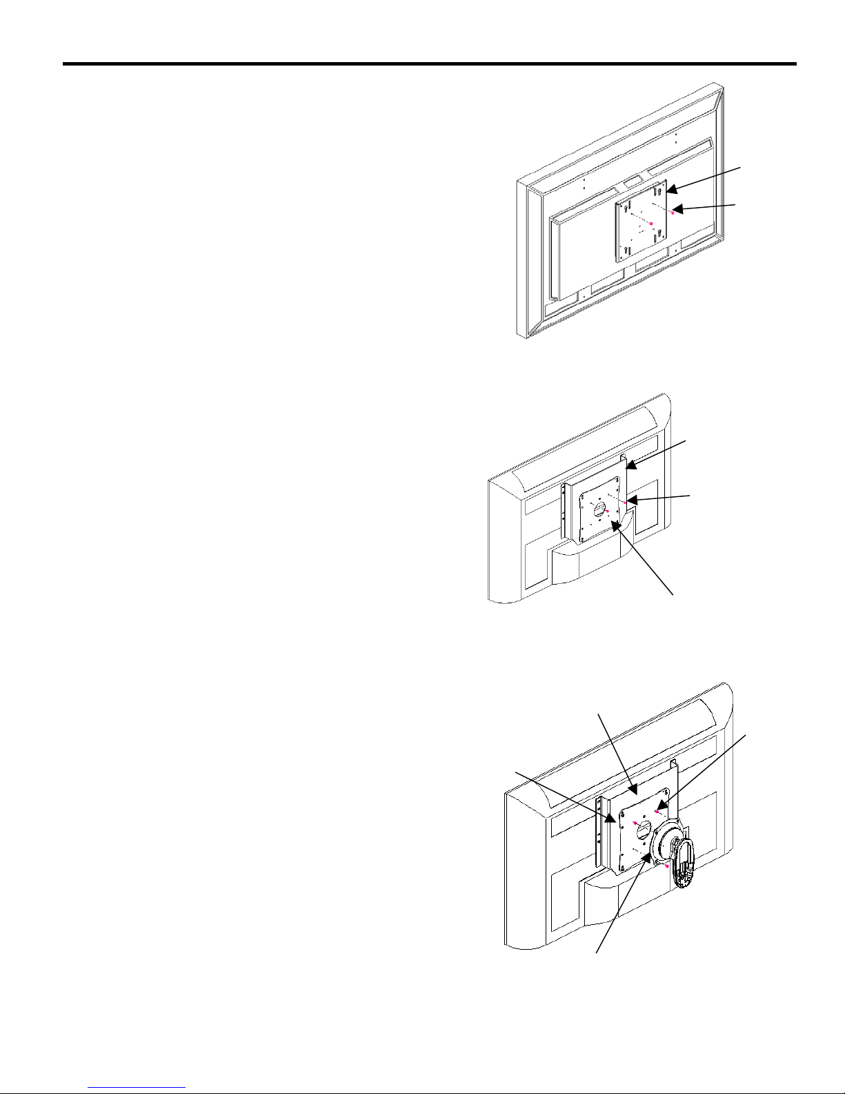
1. Start two M4 x 8mm Phillips pan head screws (50)
into top mounting holes of VESA Plate (20) or MSB
interface bracket, depending on configuration (see
Figure 11or Figure 12).
2. Align mounting holes on Centris bracket with screws
installed in MSB or VESA Plate in Step 1. See
Figure 13.
3. Install two remaining M4 x 8mm Phillips pan head
screws (50) into bottom two mounting holes of MSB
or VESA Plate (20). See Figure 13.
4. Tighten screws.
5. Proceed to “ATTACH MOUNT TO WALL BRACKET”
section on page 11.
MSB
50
Figure 11. MSB without VESA Plate
MSB
50
VESA Plate
Figure 12. MSB with VESA Plate
MSB
50
20
Figure 13. Mount MSB to Centris Bracket
Centris Bracket
10
Page 11
Installation Instructions JWP-210
ATTACH MOUNT TO WALL
BRACKET
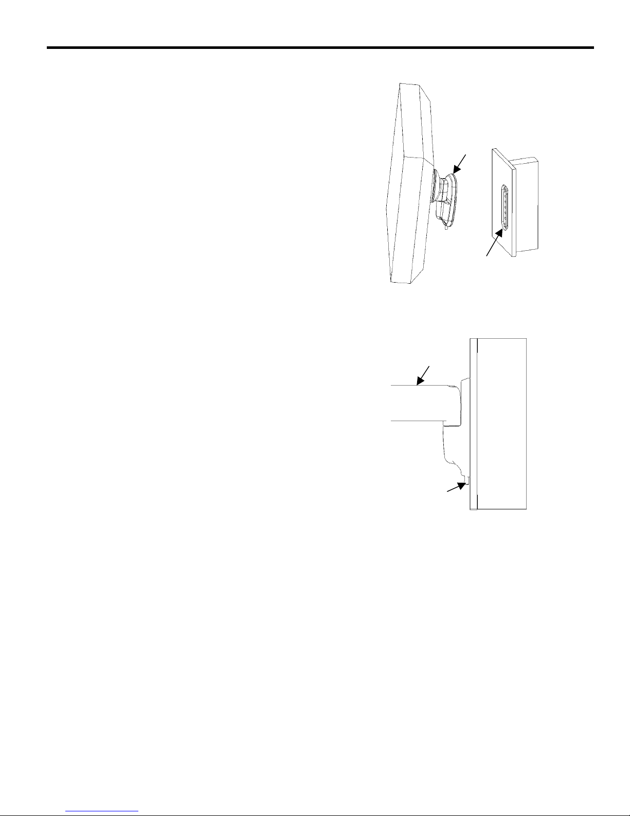
To attach mount to wall bracket:
1. Align top of mount (10) with top of wall bracket (30).
Push bottom of mount against bottom of wall bracket
until mount fits snugly in place (see Figure 14).
2. Using 5/32” hex wrench (160), secure mount to wall
bracket by tightening set screw (see Figure 15).
Figure 14. Attach Mount to Wall Bracket
10
30
10
Set Screw
Figure 15. Tighten Set Screw
11
Page 12
Installation Instructions JWP-210
j
CABLE MANAGEMENT
WARNING: Make sure your cables do not run
through a pinch points. Do not put your fingers
between movable parts.
For cable management (not shown), connect and
secure power/audio/video cables, making sure to
leave sufficient slack to allow for movement of the
display.
Lateral Tension Ad
ustment Bolt
ADJUST LATERAL TENSION
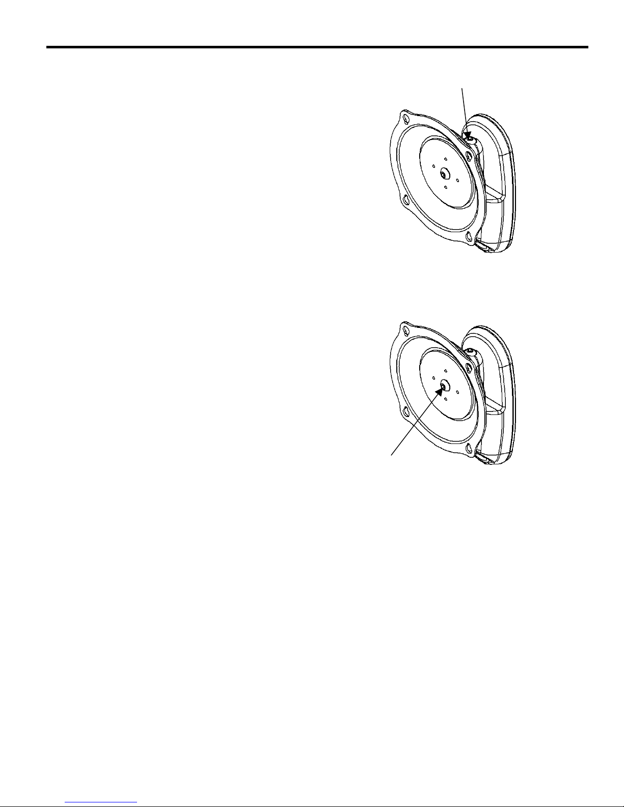
To adjust Lateral Tension:
1. Move arms laterally to check for desired tension.
2. Using a 3/16” hex wrench slightly tighten or loosen
lateral tension adjustment bolts (see Figure 16).
3. Repeat Steps 1 and 2 until desired tension is
obtained.
Figure 16. Adjust Lateral Tension
ADJUST PITCH TENSION
To adjust Pitch Tension:
1. Tilt display to check for desired tension.
2. If pitch tension in Centris Bracket requires
adjustment, perform the following steps:
a. Remove Display from Centris Bracket.
b. Using a 3/16” hex wrench, slightly tighten or
loosen pitch adjustment bolt to adjust Centris
Bracket as needed (see Figure 17).
c. Reinstall display.
3. Repeat Steps 1 and 2 until desired tension is
obtained.
Pitch Adjustment Bolt
Figure 17. Adjust Pitch Tension
12
 Loading...