

Page 1

INSTALLATION INSTRUCTIONS
Universal Clamp Accessory
Spanish Product Description
German Product Description
Portuguese Product Description
Italian Product Description
Dutch Product Description
French Product Description
FCA520
Page 2
FCA520 Installation Instructions
DISCLAIMER
Milestone AV Technologies and its affiliated corporations and
subsidiaries (collectively "Milestone"), intend to make this
manual accurate and complete. However, Milestone makes no
claim that the information contained herein covers all details,
conditions or var iations, nor does it provide for eve ry possible
contingency i n connection with the installation or use of this
product. The information contained in this document is subject
to change without notice or obligation of any kind. Milestone
makes no represe ntation of warranty, expressed or implied,
regarding the in form ation cont ai ned her ei n. Milest one assu mes
no responsibility for accuracy, completeness or suf ficiency of
the information contained in this document.
Chief® is a register ed trad emark of Milest one A V Te chnologi es.
All rights reserved.
IMPORTANT SAFETY INSTRUCTIONS
WARNING: A WARNING alerts you to the possibility of
serious injury or dea th if you do not follow the instructions.
CAUTION: A CAUTION alerts you to the possibility of
damage or destruction of equipment if you do not fol low the
corresponding instructions.
damage to equipment, or voi ding of factory wa rrant y! It is the
installer’s responsibility to make sure all components are
properly assembl ed and installed using the instructions
provided.
WARNING: Exceeding the weight capacity c an result in
serious personal inju ry or damage to equipment! It is the
installer ’s responsibil ity to make sure the combined weight of
all compo nents p laced o n the F CA520 doe s not e xceed 1 0 lbs
(13.6 kg).
WARNING: Use this mounting sy stem only for its intended
use as described in these instructions. Do not use
attachments not recom mended by the manufacturer.
WARNING: Never operate this mounting system if it is
damaged. Return the mounti ng syst em to a servi ce center fo r
examination and repa ir.
WARNING: Do not use this product outdoor s.
WARNING: RISK OF I NJURY TO PERS ONS ! D o no t us e
this mounting system to sup port video equipment such as
televisions or computer monitors.
WARNING: Failure to read, thoroughly understand, and
follow all instructions can result in serious personal injury,
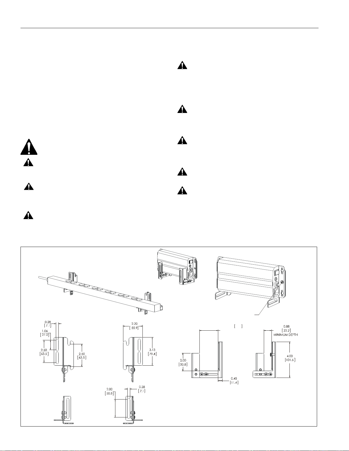
DIMENSIONS
SHOWN WITH RAXXES 12 OUTLET
POWER STRIP
SHOWN WITH
SIMULATED POWER CONDITIONER
--SAVE THESE INSTRUCTIONS--
SHOWN WITH POWER
CONDITIONER ATTACHED
DIRECTLY TO BRACKET WITH SCREWS
AND NUTS
(NOT INCLUDED)
2.13
54.0
MAX DEPTH
SUBTRACT APPROXIMATELY
1/4” FOR VELCRO
DIMENSIONS: INC HES
[MILLI METERS]
2
Page 3
Installation Ins tru ctions FCA520
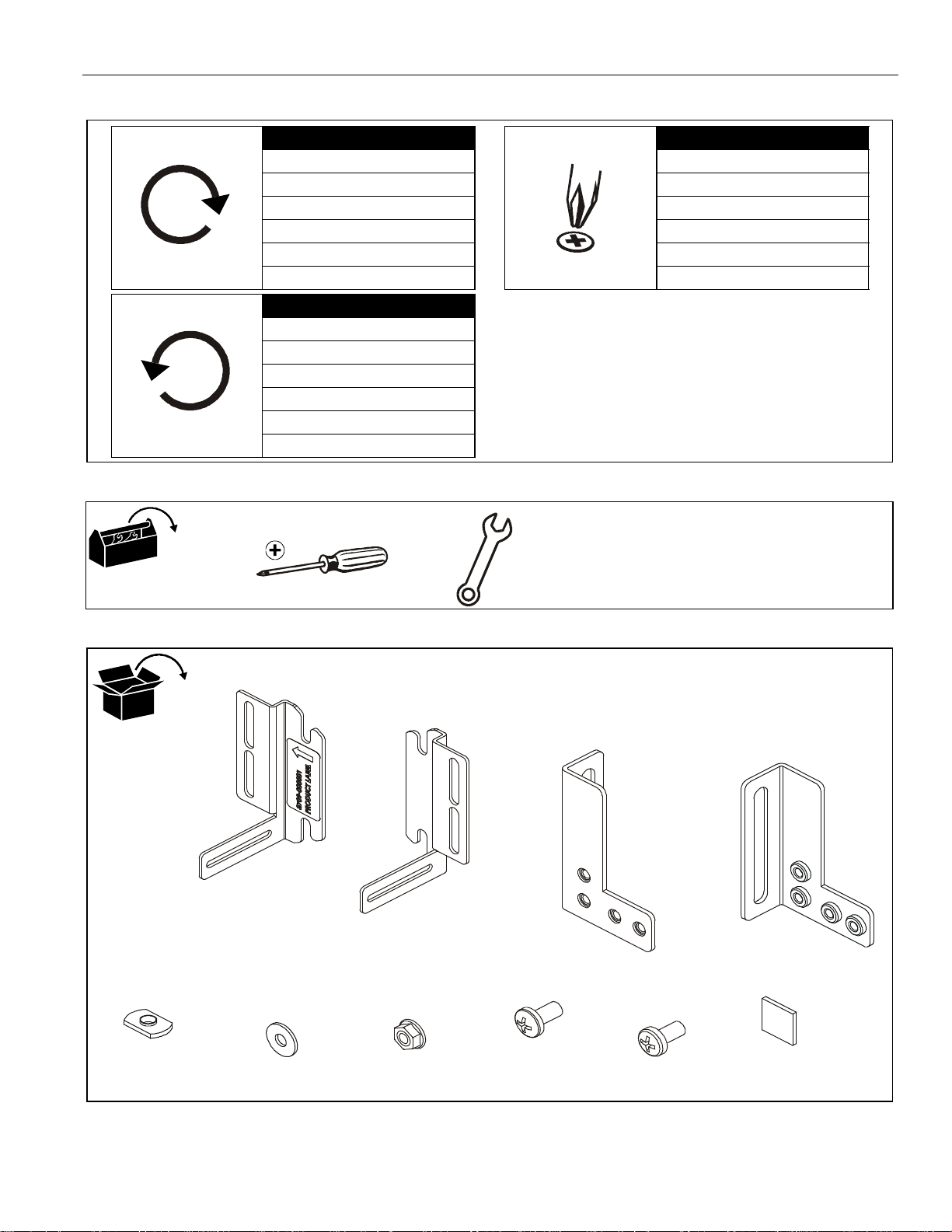
LEGEND
Tighten Fastener
Apretar elemento de fijación
Befestigungsteil festziehen
Apertar fixador
Serrare il fissaggio
Bevestiging vastdraaien
Serrez les fixations
Loosen Fastener
Aflojar elemento de fijación
Befestigungsteil lösen
Desapertar fixador
Allentare il fissaggio
Bevestiging losdraaien
Desserrez les fi xations
TOOLS REQUIRED FOR INSTALLATION
Phillips Screwdriver
Destornil lador Phillips
Kreuzschlitzschraubendre her
Chave de fendas Phillips
Cacciavite a stella
Kruiskopschroevendraaier
Tournevis à pointe cruciforme
PARTS
#2
C (1)
[Retaining bracket]
A (1)
[End bracket]
B (1)
[End bracket]
D (1)
[Retaining bracket]
E (4)
1/4-20 weldnut
F (4)
1/4"
G (2)
1/4-20
H (4)
10-24 x 3/8"
J (6)
1/4-20 x 1/2"
K (4)
1"x1"
3
Page 4

FCA520 Installation Instructions
ASSEMBLY
NOTE: The FCA520 may be assembled in various
configurations depending on size and configuration of
component to be pla ced on the FCA520. The fo llowing
guidelines should be used when determining desired
configuration:
• Always use two fasteners when connecting
end brackets (A, B) to retaining brackets (C,
D). (See Examples 1 and 2)
• May use two end brackets (A, B) without
retaining brackets (C, D) ONLY if component
can be attached directly to the end brackets
with included hardware. (See Example 3)
• Ensure that component is attached to brackets
AT MINIMUM by using the hook and loop
pieces (K).
1. Attach one retaining bracket (C) to one end bracket (A)
using two 10-24 x 3/8" Phillips pan machine screws (H).
(See Figure 1)
2. Repeat Step 1 for remaining retaining bracket (D) and end
bracket (B). (See Figure 1)
Example 1
3. OPTIONAL: Attach component di r ect ly to end brac ket s (A,
B) using screws and nuts (not included). (See Fi gure 2)
(A)
3
x 2
(Hardware not included)
Example 3
(B)
Figure 2
INSTALLATION
1. Insert four 1/4-20 weldnuts (E) in to slot in mount extrusi on.
(See Figure 3)
(A)
(C)
(D)
Extrusion
slot
(E) x 4
1
1
2
(H) x 4
Figure 3
Example 2
4
Figure 1
Page 5

Installation Ins tru ctions FCA520
2. Attach conf igured bra ckets to weld nuts using four
1/4-20 x 1/2" Phillips pan head screw (J) and four 1/4" flat
washers (F) into installed weldnuts (E). (See Figure 4)
weldnuts
2
(J) x 4
(F) x 4
Figure 4
3. Put hook and loop squares (K) together to form two
squares.
4. Remove paper from one side of both squares.
5. Attach hook and loop squares to brackets. (See Figure 5)
6. Remove paper from hook and loop squares and place
component on brackets, pressing it against hook and loop
squares. (See Fi gure 5)
7. OPTIONAL (attaching power strip): Attach power strip
(not included) to bracket assemblies through slots in
retaining brac kets and in power st rip using two 1/4- 20 x 1/2"
Phillips head screws (J) and two hex nuts with f lange (G).
(See Figure 6)
Top view
(G) x 2
Bracket
(J) through
bracket and
power strip
Power
strip
2
(J) x 2
Figure 6
6
5
(K) x 2
Figure 5
5
Page 6

FCA520 Installation Instructions
6
Page 7

Installation Ins tru ctions FCA520
7
Page 8

FCA520 Installation Instructions
Chief Manufacturing, a products division
of Milestone AV Technologi es
8800-002259 Rev 00
2012 Milestone AV Technologies, a
Duchossois Group Company
www.chiefmfg.com
0610
USA/International A 6436 City West Par kway, Eden Prairie, MN 55344
P 800.582.6480 / 952.225.6000
F 877.894.6918 / 952.894.6918
Europe A Franklinstraat 14, 6003 DK Weert, Netherlands
P +31 (0) 495 580 852
F +31 (0) 495 580 845
Asia Pac if ic A Office No. 1 on 12/F, Shatin Galleria
18-24 Shan Mei Street
Fotan, Shatin, Hong Kong
P 852 2145 4099
F 852 2145 4477
 Loading...