

Page 1
INSTALLATION INSTRUCTIONS
EVCM-100D
Magna Lift™ Electric Ceiling Mount
Prior to assembly, unpack carton completely and verify contents.
If you are missing any of the following components, please contact Customer Service at 1-800/582-6480
BEFORE PROCEEDING, READ INSTALLATION INSTRUCTIONS COMPLETELY
WARNING! IMPROPER INSATLLATION MAY RESULT IN SERIOUS
PERSONAL INJURY! All components must be securely fastened to each other
and to the ceiling. The overhead support must be capable of supporting five times
the weight of the mount and equipment combined. If it cannot is MUST be
reinforced.
Unit Specifications
Motor Operation Limits
Run Time - 12 Minutes*
Cool Time - 25 Minutes
Run Time - 12 Minutes
Do not exceed two cycles without an extended cooling period of 45 minutes. To prevent
damage to the Magna Lift, the unit will shut down for cooling if overheated.
* It will take approximately 11 minutes to fully lower and raise 20 feet of cable under maximum load.
Maximum Weight Capacity ....................... 250 lbs. (113.5)
Maximum Travel ....................................... 20 feet (609.6 cm)
Unit Weight ................................................ 48 lbs. (21.6 kg)
Electrical Requirements ........................... 115 volts, 60 Hz, 1.6 amps continuous
Read instructions completely before installing unit and connecting power.
1. Ensure 115-volt electrical power is readily available at the installation location.
2. Ensure support for the EVCM-100 ceiling mount is securely installed to the ceiling; if not
the ceiling must be reinforced. Improper installation may result in serious personal
injury.
3. Use the optional QD-1 for simplified installation or attach the EVCM-100 Magna-Lift
directly to the NPT 1 1/2" column installed in your ceiling as follows:
A Thread the unit on the NPT 1 1/2" column and tighten securely using pipe
wrench.
B After unit is tightened securely, install the thread locking set screw [Figure 1,
Item (1) into the coupler, tightening it against threads on column.
CHIEF MANUFACTURING INC. 1-800-582-6480, Fax: 1-877-894-6918, Email: chief@chiefmfg.com
Page 1 of 3 8808-000006 RevA
Page 2
1 ½” NPT Couple
r
8
1
5
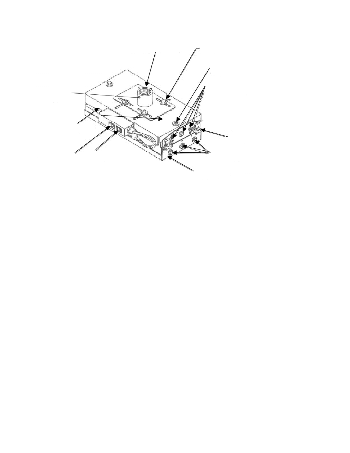
Figure 1
1. Thread Locking Screw 6. Adapter Plate
2. Power Inlet 7. Hanging Bracket Bolts
3. (4x) Locking Hasp 8. Pitch Adjustment Bolts
4. Power Switch 9. Adjustment
5. Rocker/Control Switch 10. Adjustment Nuts
7
4. Using the appropriate power cord, provide power to the EVCM-100. The power inlet is a
general-purpose IEC-320 power inlet for Class 1 applications rated at 10A international,
15A North America. The main plug to the appliance inlet shall be used as the primary
disconnect device.
5. Make sure the area directly below the unit is clear of all individuals and obstructions and
lower it to floor/service level as follows:
A Unlock the four locking clasps [See Fig. 1, Item (3)] on each side of housing,
making sure the locking clasps are clear of the keeper plates, by turning them
180°counter-clockwise.
B Turn power switch (4) to ON.
C Depress and hold the down arrow side of rocker/control switch (5) until the
adapter plate (6) is to floor/service level.
D With unit resting on floor or service platform, depress the down arrow side for
approximately four seconds. This will provide slack in the cable for easy
movement of adapter plate.
6. Attach hanging bracket to the projector. See the enclosed HB instructions (projector
Model determines which hanging bracket is required for your EVCM-100).
7. After attaching the hanging bracket to the projector, install the adapter plate to the
hanging bracket using six hanging bracket bolts (7) (three on each side) through the
holes in the hanging bracket and tighten securely into the adapter plate.
Page 2 of 3
Page 3

8. Before raising projector to ceiling, make sure all fasteners are securely tightened to the
projector and the adapter plate.
9. Raise unit to ceiling as follows:
A Depress and hold the arrow side of rocker/control switch [Figure 1, Item (5)] until
the adapter plate is seated to the ceiling mount housing.
B When adapter plate is properly seated, the unit will turn off.
C After the adapter plate is seated to ceiling housing, make sure hasps connect
with keeper plates and lock the four locking hasps.
D Turn clockwise to lock adapter plate to ceiling mount housing and turn the power
switch (4) to OFF. You can now attach power and cables to the projector.
See projector alignment sheet for projector alignment.
10. To lower projector for servicing, disconnect all power cables and signal cables from the
projector. Repeat step 5 to lower.
AGNA-LIFT ELECTRIC CEILING MOUNT EVCM-100D
Projector Alignment Instructions
WARNING! During projection alignment, loosen mounting hardware only
enough to allow for necessary movement. Loosening or removal of mounting
hardware may result in serious damage to equipment or personal injury.
Vertical Elevation (pitch): Adjust pitch by loosening six-pitch adjustment bolts (See Figure
1,Item 8). Loosen both sides and adjust pitch by tilting projector in the desired direction. When
desired pitch is obtained, securely tighten bolts on both sides.
Horizontal Tilt (roll): Adjusted roll by loosening six-pitch adjustment bolts (8) and turning
adjustment bolt (9) clockwise to raise and counter clockwise to lower. Roll adjustment can be
done on both sides of unit. When desired roll is obtained, securely tighten the six-pitch
adjustment bolts.
Positive Registration Lock: Tighten pitch adjustment bolts. You can now lower the unit to the
ground and remove the projector, without losing projector registration, by removing six bolts (7)
holding the HB hanging bracket to the EVCM.
Horizontal Adjustments: Loosen, but do not remove, nuts holding the top slide bracket (10).
When nuts are loose, adjust unit 1 1/2" in any direction.
Page 3 of 3
 Loading...