

Page 1
US -INSTRUCTION MANUAL FOR WIRE WELDING MACHINE page 2
F -MANUEL D’INSTRUCTIONS POUR POSTE A SOUDER A FIL page 9
E -MANUAL DE INSTRUCCIONES PARA SOLDADORA DE HILO pag. 17
Spare parts and electrical schematic
Pièces détachées et schéma électrique
Partes de repuesto y esquema eléctrico
Page. Sid. sel.: 25 ÷ 28
15/07/2015
3.300.117
Page 2
2
INSTRUCTION MANUAL FOR WIRE WELDING MACHINE
IMPORTANT: BEFORE STARTING THE EQUIPMENT,
READ THE CONTENTS OF THIS MANUAL, WHICH MUST
BE STORED IN A PLACE FAMILIAR TO ALL USERS FOR
THE ENTIRE OPERATIVE LIFE-SPAN OF THE MACHINE.
THIS EQUIPMENT MUST BE USED SOLELY FOR WELDING OPERATIONS.
1 SAFETY PRECAUTIONS
WELDING AND ARC CUTTING CAN BE
HARMFUL TO YOURSELF AND OTHERS. The
user must therefore be educated against the hazards,
summarized below, deriving from welding operations.
For more detailed information, order the manual code
3.300.758
ELECTRIC AND MAGNETIC FIELDS - May be dangerous.
· Electric current following through any conductor causes localized Electric and Magnetic Fields (EMF). Welding/cutting current
creates EMF elds around cables and power sources.
· The magnetic elds created by high currents may affect
the operation of pacemakers. Wearers of vital electronic
equipment (pacemakers) should consult their physician
before beginning any arc welding, cutting, gouging or
spot welding operations.
· Exposure to EMF elds in welding/cutting may have
other health effects which are now not known.
· All operators should use the followingprocedures in or-
der to minimize exposure to EMF elds from the welding/
cutting circuit:
- Route the electrode and work cables together
- Secure them with tape when possible.
- Never coil the electrode/torch lead around your body.
- Do not place your body between the electrode/torch
lead and work cables. If the electrode/torch lead
cable is on your right side, the work cable should also
be on your right side.
- Connect the work cable to the workpiece as close as
possible to the area being welded/cut.
- Do not work next to welding/cutting power source.
EXPLOSIONS
· Do not weld in the vicinity of containers under
pressure, or in the presence of explosive dust,
gases or fumes. · All cylinders and pressure regulators used in welding operations should be handled with
care.
ELECTROMAGNETIC COMPATIBILITY.
This machine is manufactured in compliance with the instructions contained in the standard IEC 60974-10 (CL.
A), and must be used solely for professional purposes in
an industrial environment. There may be potential difculties in ensuring electromagnetic compatibility in nonindustrial environments.
DISPOSAL OF ELECTRICAL AND ELECTRONIC
EQUIPMENT.
Do not dispose of electrical equipment together
with normal waste! Electrical equipment that has
reached the end of its life must be collected separately
and returned to an environmentally compatible recycling
facility. As the owner of the equipment, you should get information on approved collection systems from our local
representative.
IN CASE OF MALFUNCTIONS, REQUEST ASSISTANCE
FROM QUALIFIED PERSONNEL.
Extra precautions are to be observed when working on
elevated positions.
Electromagnetic compatibility
In Canada, the EMC classication does not apply to arc
welding power source.
Safety standards
To provide minimum requirements and recommendations
to protect persons who work in an
environment affected by welding, cutting, and allied processes see CAN/CSA-W117.2 standard.
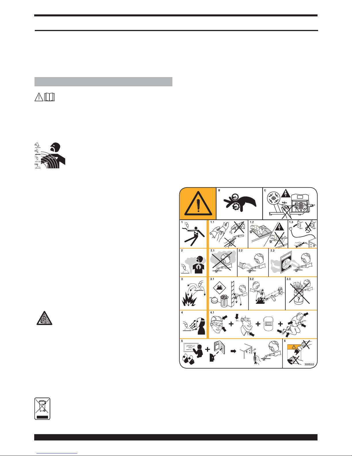
1.1 WARNING LABEL
The following numbered text corresponds to the label
numbered boxes.
B. Drive rolls can injure ngers.
C. Welding wire and drive parts are at welding voltage
during operation — keep hands and metal objects
away.
1 Electric shock from welding electrode or wiring can kill.
1.1 Wear dry insulating gloves. Do not touch electrode
with bare hand. Do not wear wet or damaged gloves.
Page 3
3
1.2 Protect yourself from electric shock by insulating
yourself from work and ground.
1.3 Disconnect input plug or power before working on
machine.
2 Breathing welding fumes can be hazardous to your
health.
2.1 Keep your head out of fumes.
2.2 Use forced ventilation or local exhaust to remove
fumes.
2.3 Use ventilating fan to remove fumes.
3 Welding sparks can cause explosion or re.
3.1 Keep ammable materials away from welding.
3.2 Welding sparks can cause res. Have a re extingui-
sher nearby and have a watchperson ready to use it.
3.3 Do not weld on drums or any closed containers.
4 Arc rays can burn eyes and injure skin.
4.1 Wear hat and safety glasses. Use ear protection and
button shirt collar. Use welding helmet with correct
shade of lter. Wear complete body protection.
5 Become trained and read the instructions before
working on the machine or welding.
6 Do not remove or paint over (cover) label.
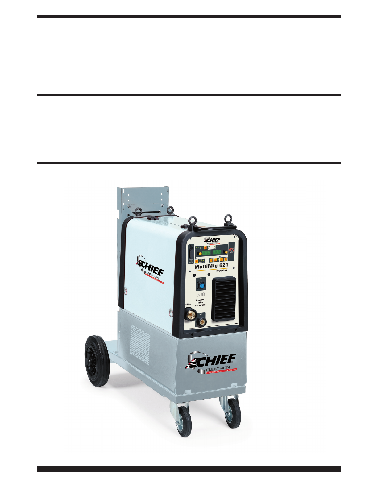
2 GENERAL DESCRIPTIONS
2.1 POWER SOURCE
The MULTIMIG 621 is an equipment suitable for synergic
pulsed MIG/MAG, synergic not pulsed MIG/MAG and
conventional MIG/NAG welding, developed with inverter
technology. The power source is equipped with a 2-roller
wire feeder.
This welding machine must not be used to defrost pipes.
2.1.1 Explanation of technical specications
This machine is manufactured according to the following
international standards: IEC 60974.1 - IEC 60974.5 -IEC
60974.10 CL. A - IEC 61000-3-12 (see note 2)
N°. Serial number. Must be indicated on any
request regarding the welding machine.
3
~
f
1
f
2
Three-phase static frequency converter
Transformer - rectier.
MIG Suitable for MIG-MAG welding.
U0. Secondary open-circuit voltage.
X. Duty cycle percentage. The duty cycle
expresses the percentage of 10 minutes
during which the welding machine may run
at a certain current without overheating.
I2. Welding current
U2. Secondary voltage with current I2
U1. Rated supply voltage
1~ 50/60Hz 50- or 60-Hz single-phase power supply.
I1 Max Max. absorbed current at the corresponding
current I2 and voltage U2.
I1 eff This is the maximum value of the actual
current absorbed, considering the duty
cycle. This value usually corresponds to the
capacity of the fuse (delayed type) to be used
as a protection for the equipment.
IP23S Protection rating for the housing.
S
Suitable for use in high-risk environments.
NOTE:
1- The machine has also been designed for use in
environments with a pollution rating of 1. (See IEC
60664).
2- This equipment complies with IEC 61000-3-12
provided that the maximum permissible system
impedance Zmax is less than or equal to0,107 at
the interface point between the user's supply and the
public system. It is the responsibility of the installer
or user of the equipment to ensure, by consultation
with the distribution network operator if necessary,
that the equipment is connected only to a supply with
maximum permissible system impedance Zmax less
than or equal to 0,107.
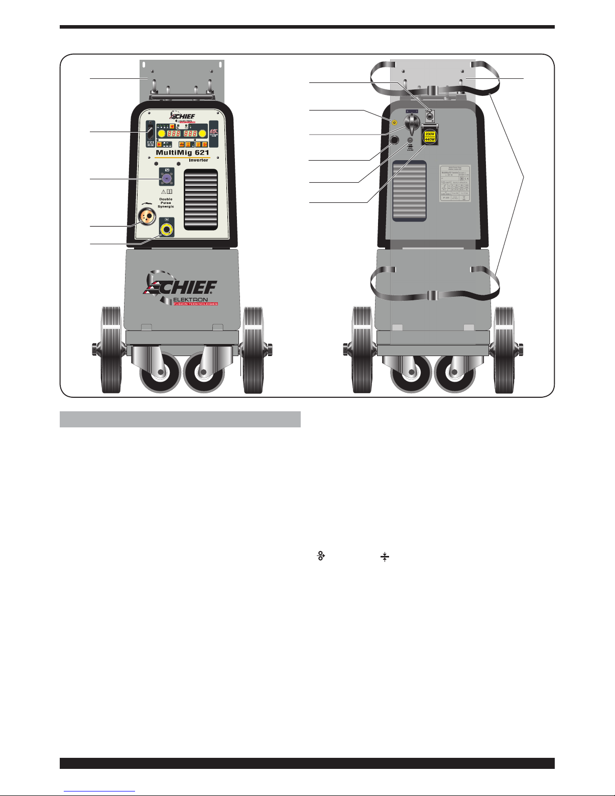
3 DESCRIPTION OF POWER SOURCE (Fig. 1)
A – Socket (-): this is where the earth cable is to be
connected.
B – Central adapter: Connect the welding torch.
C – Connector: For connecting remote controls and the
welding control cable Push–Pull.
F - Connector: Connector type DB9 (RS232 serial line)
to use for updating the microprocessor programs.
G – Pressure switch socket. Socket which receives the
cable from the pressure switch located inside the
cooling unit (optional).
H – Fuse holder.
I - Socket. Socket which receives the power supply
cable of the cooling unit (optional).
L - ON/OFF switch.
M – Power cable.
N – Gas hose.
O – Cylinder support.
P – Cylinder support straps.
3.1 COOLING UNIT (optional).
This cooling unit was designed to cool the welding torches
used for MIG/MAG welding. It must be used exclusively
with this power source.
3.2 DESCRIPTION OF PROTECTIVE DEVICES.
3.2.1 Coolant pressure protective device.
This protection is achieved by means of a pressure switch,
inserted in the uid delivery circuit, which controls
a microswitch. Low pressure is indicated by the
abbreviation H2O ashing on the display AM.
3.2.2 Fuse (T 2A/250V - Ø 5x20).
This fuse is inserted to protect the motor pump, and is
located on the rear panel of the welding machine H.
3.2.3 Positioninng on sloping planes.
Since this welding machine is equipped with wheels
without brake, make sure the machine is not positioned
on sloping planes, to avoid tilting or noncontrolled motion
of the machine itself.
Page 4
4
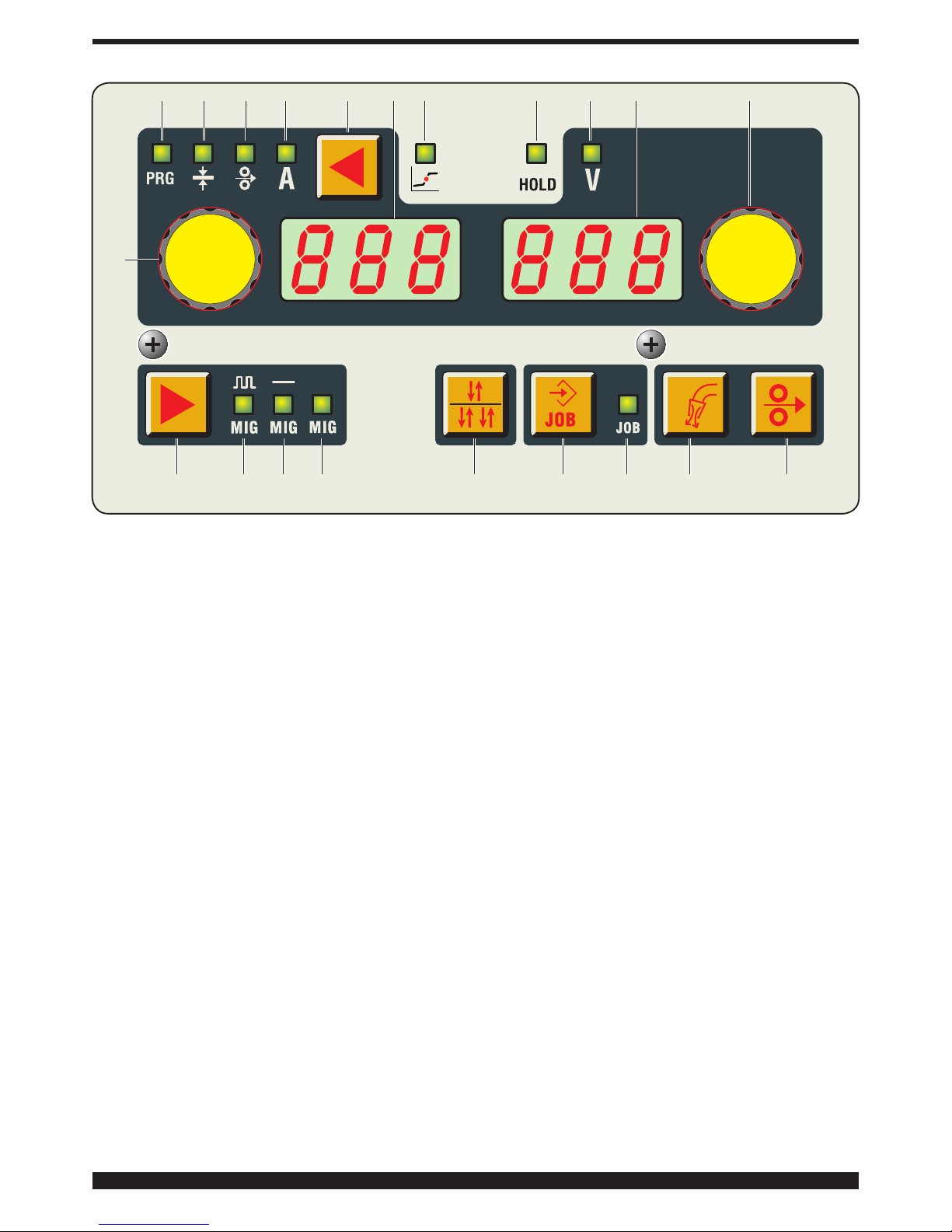
4 DESCRIPTION OF CONTROL PANEL (Fig. 2)
AE selection key.
Each brief pressure selects the size, adjustable via the
AI knob. The sizes which can be selected are shown by
LEDs AA/AB/AC/AD.
LED AA PRG.
Indicates that the display AL shows the set program
number.
LED AB Thickness.
The AL display shows the recommended thickness
based on the set current and wire speed. Active only in
synergic MIG processes.
LED AC Wire speed.
Indicates that the display AL shows the wire speed in
welding.
LED AD Current.
Indicates that the display AL shows a welding current.
During welding always shows the measured current; with
the machine at a standstill, if AG is OFF, shows the set
current.
LED AF - Globular position.
May not be selected. Active in synergic MIG process.
When lit, this signals that the pair of values chosen for
welding may give unstable arcs and splatters.
LED AG - Hold.
May not be selected. It signals that the values shown on
the displays AL and AM (normally Amperes and Volts) are
those used during last welding. Activated at the end of
each welding session.
LED AH - Voltage.
In all welding processes, it indicates that the display AM
shows the re-set welding voltage or, if in combination with
LED AG lit, the last measured voltage.
Knob AI.
The following values are set: welding current A, wire speed
( ), thickness ( ), program number PRG. In the service
functions the following are selected: TRG, SP, HSA, CrA,
PrF, PoF, Acc, bb, L, Dp, PPF, Ito, Fac.
In MIG synergic processes when a value is adjusted the
other values are adjusted as well. All these values are
shown on the display AL.
Knob AN.
The following sizes are set:
In synergic MIG the arc length, in conventional MIG the
welding voltage.
Inside the service menu, according to the value set
by knob AI it selects the set value, the activation or
desactivation of the same, or an additional selection to be
made inside the fuction.
C
A
B
A
F
O
G
N
L
M
H
I
Fig. 1
O
P
Page 5
5
Display AL.
In all welding processes, it numerically displays the
selections made via the selection key AE and adjusted
via the knob AI.
For the welding current (LED AD) it displays the amperes.
For the wire speed (LED AC) it displays the meters per
minute.
For the thickness (LED AB) it displays the millimeters.
For (LED AA) it displays the set program number.
In the service functions the following are selected: TRG,
SP, HSA, CrA, PrF, PoF, Acc, bb, L, Dp, PPF, Ito, Fac.
For the parameters within the service functions that are
shown on the display AM, see the paragraph on service
functions.
When the machine is in the warning mode, it displays
a ashing warning (exemple: OPN if the lateral panel is
open. When the machine is in the error mode it displays
Err.
Display AM.
Displays by the number: in synergic MIG the arc length
and in conventional MIG the welding voltage.
For the welding voltage (LED AH) it displays the Volts. For
the arc length (LED AHoff) it displays a number between
9.9 and +9.9, 0 being the recommened value.
For the parameters in the MIG service function, that are
shown on the display AM, see the paragraph on service
functions .
When the machine is in error mode it displays the
corresponding error code between 1 and 99.
Selection key AO.
Each time this key is pressed, the selected process is
shown by LED AP/AQ/AR.
LED AP Pulsed MIG.
Shows that the selected process is the synergic MIG
Pulsed.
LED AQ SYNERGIC MIG.
Shows that the selected process is synergic MIG.
LED AR CONVENTIONAL MIG.
Shows that the selected process is conventional MIG.
Selection key AU.
Each brief pressure selects 2 stages mode (MANUAL) and
the 4 stages mode (AUTOMATIC), the selection is shown
on the display AL.
In the 2 stages mode the machine begins welding when
the welding torch trigger is pressed, and stops when
released.
In the 4 stages mode to begin welding press and release
the welding torch trigger; to interrupt, you must press and
release it again.
Selection key AV. (JOB)
Saving and restoring of the stored processes.
To save a working condition (JOB), just hold down for at
least 3 seconds the key AV, the LED AZ glows, on the
display AL the abbreviation STO ashes and on display
AM the number of the rst available position ashes.
Knob AN is used to select the saving position; press again
key AV until a sound will conrm that it has been saved
and the selected number stops ashing.
To restore the saved number just briey press key AV and
restore the number by means of knob AN. Up to 99 pairs
od current/voltage values may be saved.
To delete a saved number, press for at least 3 seconds
AA
AI
AO AP AQ AR AU AV AZ AY AW
AB AC AD AE AFAL AG AH AM AN
Fig. 2
Page 6

6
key AV, turn knob AI until the display ALshows the
abbreviation DEL and press the key againAV for 3 more
seconds.
A current/voltage parameter may be restored outside
saving for both using or changing it. To restore it press
for 3 seconds key AV, display by menas of knob AI the
number to be restored and show on display AL, with
knobANthe abbreviation rcL; now just press for at least
3 seconds key AV.
LED AZ JOB.
Shows that you are inside the saving menu of the saved
working points.
Selection key AY.
Gas Test .
When this jey is pressed gas stars owing; to stop it press
the key again.
If the second press does not takes place the gas output
is interrupted after 30 seconds
Selection key AW.
Wire test.
Allows the wire feed with no current or voltage present.
When this key is held down, during the rst 5 seconds
the wire advances at the speed of 1 meter per minute and
then the speed increases up to 8 meters per minute.
When this key is released the motor stops immediately.
5. SERVICE FUNCTIONS.
Press the key AE, and hold it down for at least 3 seconds
to enter the submenu. Turning the knob AI you select the
function, shown on the display AL and turning the knob
AN you select the type of operation or the value, shown
on the display AM. To return to the normal display, press
and release the key AE immediately.
1- H2O (Cooling unit, optional).
Turning the knob AN you select the type of operation:
OFF = shut off, ON C = always on, ON A = automatic
start-up.
When the automatic mode is selected the pump begins
working immediately at each welding start command and
stops 3 minutes after the welding is completed.
At each power source start-up a short pump test takes
places for15 seconds.
If an insufcient presssure is detected the machine goes
into warning mode and H2O ashes on display AM.
If th elow pressure condition persists for more than 30
seconds, the pump is disactivated and the machine goes
to error mode (ERR 75).
2- TRG.
Choice between 2- or 4- stages , 3 levels, the selection
2t and 4t with the selection key AU, without entering the
service functions.
2t the machine begins welding when the welding torch
trigger is pressed, and stops when released. 4t to begin
welding press and release the welding torch trigger; to
interrupt, you must press and release it again. 3L this
procedure is active in the synergic processes. Specially
well suited to weld aluminum.
3 currents are available that can be used in welding by
means of the welding torch start button. The current and
the slope values are set as follows:
SC starting current (Hot Start). With the possibility of
adjusting from 1 to 200% of the welding current, a value
adjusted using the knob AN.
Slo slope. Possibility of adjusting from 1 to 10 seconds.
Denes the connection time between the rst current SC
with the welding current and the second current with
the third current CrC ( crater ller current), a value set by
means of knob AN.
CrC - «Crater ller» current. With the possibility of
adjusting from 1 to 200% of the welding current, a value
adjusted using the knob AN.
Welding starts at the welding torch button pressure, the
named pressure will be the starting pressure SC.
This current is kept as long as the welding torch button
is held down; when the welding torch trigger is released
the rst current connects to the welding current, set by
means of knob AI, and is kept as long as the welding
torch button is held down. When the welding torch trigger
is pressed again the welding current connects to the third
current CrC . and is kept as long as the welding torch
trigger is held down. When the welding torch trigger is
released welding stops.
3- SP (spot-welding).
Off/ON activates and disables the spot function.
The spot welding time tSP is set from 0.3 to 5 seconds.
The interval between two spots tIN is set from 0,3 to 5
seconds.
This function is è blocked when function 3L is activated.
4- HSA (Automatic Hot Start).
This function is blocked when function 3L is activated and
works only with the synergic processes. Once the function
has been enabled using the AN knob, the operator may
adjust the level of the starting current SC (Hot Start), with
the possibility of adjusting from 1 to 200% of the welding
current, a value adjusted using the knob AN .
The duration tHS (default 130%) of this current may also
be adjusted from 0.1 to 10 seconds.) (default 0,5 sec.).
The switching time Slo between the SC current and
the welding current may also be adjusted from 0.1 to 10
seconds.(default 0.5 seconds).
5- CrA (nal crater ller).
This function may be selected by means of key AI and is
working during welding 2t or 4t and also in combination
with function HSA, if so requested.
After activating function «On» by means of knob AN,
rotate knob AI to display the abbreviations:
Slo = Fitting time between the welding current and the
crater lling time. Default 0.5 sec.
Range 0.1 – 10 seconds.
CrC = crater lling time expressed as a percentage of
the welding wire speed. Default 60%. Range from 10 to
200%.
TCr = duration of the lling current time. Default 0.5 sec.
Range 0.1 – 10 seconds.
6- PrF (Pre-gas).
The adjustment may range from 0 to 3 seconds.
Page 7
7
7- Pof (post-gas).
The adjustment may range from 0 to 30 seconds.
8- Acc (soft-start ).
The adjustment may range from 0 to 100%.
It is the wire speed, expressed as a percentage of the
speed set for the welding, before the wire touches the
workpiece.
This adjustment is important in order to always achieve
good starts.
Manufacturer setting «Au»: automatic.
The value can be changed using the knob AN. If, once
changed, you wish to return to the original settings,
press the key AV until the abbreviation «Au» reappears on
the display AM.
9- BB (Burn-back).
The adjustment may range from 4 to 250ms. Serves to
adjust the length of the wire leaving the contact tip after
welding. The higher the number, the more the wire burns.
Manufacturer setting «Au» automatic.
If, once changed, you wish to return to the original settings,
press the key AV until the abbreviation «Au» reappears on
the display N.
10- L (impedance).
The adjustment may range from -9.9 to +9,9. Zero is the
number set by the manufacturer:if the number is negative,
the impedance decreases and the arc becomes harder; if
increased, it becomes softer.
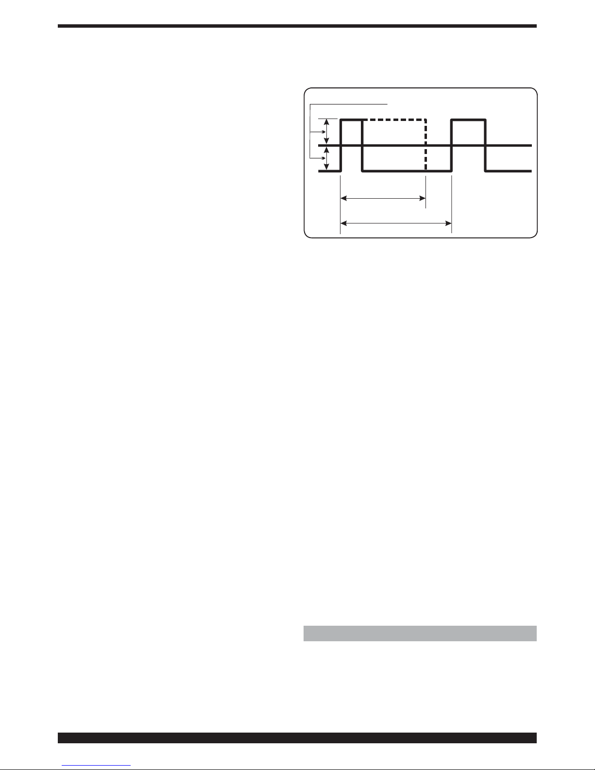
11- dP ( Double pulse)
This type of welding varies the current intensity between
two levels and may be included in all synergic processes.
Before setting, it is necessary to make a short bead to
determine the speed closest to the type of welding that
you will be doing. This determines the reference speed.
To activate the function proceed as follows:
A)- Activate the function by turning knob AN until the
abbreviation On reappears on the display AM.
B)- Turn knob AI no uni tl the abbreviation FdP reappears
(double pulse frequency) on the display AL. The display
AM reads the abbreviation OFF.
Turn the knobAN to select the working frequency
(adjustment from 0.5 to 5 Hz). The selected value is shown
on the display AM.
C) Turn knobAI until the abbreviation ddP (difference in
m/min of the double pulse) is displayed.
Turn the knob AN to select the meters per minute (range
from 0.1 to 3m/min) that will be added to and subtracted
from the reference speed (default 1m/min).
D)Turn the knob AI until the display shows the the
abbreviation tfP. This is the duration of the highest wire
speed, thus the highest current. It is expressed as a
percentage of the time gained from the Fdp frequency
(see gure 3).
Turn knob AN to adjust the percentage. Range between
25 and 75% (default 50%).
E)-Turn knobAI unitl the display shows the abbreviationAdP
(arc length of the highest current). Range between -9.9
and 9.9% (default 0).
When welding, check that the arc length is the same for
both currents; turn the AN knob to correct it if necessary.
Note: it is possible to weld within the double pulse
functions.
DdP= 0,1÷3 m/min
tdP T= 25÷75% di
T Fdp= 1/ (0,5÷5 Hz)
==
Reference
speed
Fig. 3
Once these adjustments have been made, to return to the
control panel normal display briey press key AE.
Should it be necessary to adjust the arc length of the
lowest current/lowest speed, adjust the arc length of
the reference speed. When the reference speed moves,
the previous settings must also be repeated for the new
speed.
12- PP (push-pull).
By using Push-Pull torch function PPF (Push Pull Force)
is enabled which adjusts the drive torque of the push-pull
motor in order to make the wire feed linear. The adjustment
may range from 99 to -99 and is done through knob AN..
Standard adjustment is 0.
13- Ito. (Inching time out).
The purpose is to stop the welding machine if the wire
ows after starting with no passage of current.
The wire ow from the welding torch can be adjusted
from 5 to 50 centimeters by means of knob AN. When
this function is restored, it may be activated (On) or cut
off (Off).
14- Fac. (factory).
The purpose is to return the welding machine to the
original settings provided by the manufacturer. With the
function selected, the display AM shows noP = restores
the welding machine to the original settings disregarding
the stored programs, Prg = deletes all stored programs
and ALL = restores the welding machine to the original
settings.
To save the desired function press the button AV, the
abbreviation shown on the display AM will begin ashing;
after a few seconds, a sound will conrm that it has been
saved.
6 INSTALLATION
The welding machine must be installed by skilled
personnel. All connections must be made in full
compliance with current safety laws.
Page 8

8
6.1 PLACEMENT
The weight of the welding machine is approximately 67Kg
therefore for lifting it see Fig.4.
Fig. 4
Position the unit in an area that ensures good stability, and
efcient ventilation so as to prevent metal dust (grinding)
from entering.
6.2 ASSEMBLY
Mount the rear wheels.
Mount the plug on the power cord, being especially
careful to connect the yellow/green conductor to the earth
pole. Make sure that the supply voltage corresponds to
the rated voltage of the welding machine.
Size the protective fuses based on the data listed on the
technical specications plate.
Position the cylinder onto the support O fasten it with
belts P and connect the gas hose to the pressure reducing
valve. Mount the welding torch.
To make sure that the groove of the rollers matches the
wire diameter used, open the mobile lateral side, remove
the cover CA, release the wire press rollers by means of
the pressure adjusting knob BN, replace the rollers and
remount the cover CA. (See g.5).
Fig. 5
BN
BN
CA
Mount the wire coil and slip the wire into the feeder and
welding torch sheath.
Block the wire press rollers with the knob BN and adjust
the pressure.
Turn on the machine.
Adjust the gas by means of key AY and then feed the wire
by means of key AW.
7 WELDING
Welding Synergic Pulsed MIG LED AP on.
Select the PRG number based on the wire diameter to be
used, the type and quality of the material, and the type of
gas, using the instructions located inside the wire feeder
compartment.
Set the functions in the submenu according to the
instructions under paragraph «Service functions».
The welding parameters are set by means of knob AI.
Synergic MIG Welding LED AQ on.
Select the PROG number based on the wire diameter
to be used, the type and quality of the material, and the
type of gas, using the instructions located inside the wire
feeder compartment.
Set the functions in the submenu according to the
instructions under paragraph «Service functions».
Adjust the wire speed and the welding voltage using the
knob AI.
Conventional MIG Welding LED AR on.
Select the PROG number based on the wire diameter
to be used, the type and quality of the material, and the
type of gas, using the instructions located inside the wire
feeder compartment.
Set the functions in the submenu according to the
instructions under paragraph «Service functions».
Adjust the wire speed and the welding voltage using the
knob AI and AN respectively.
8 MAINTENANCE
Any maintenance operation must be carried out by
qualied personnel in compliance with standard IEC
60974-4.
8.1 GENERATOR MAINTENANCE
In the case of maintenance inside the machine, make sure
that the switch L is in position “O” and that the power
cord is disconnected from the mains.
It is also necessary to periodically clean the interior of
the machine from the accumulated metal dust, using
compressed air.
8.2 PRECAUTIONS AFTER REPAIRS.
After making repairs, take care to organize the wiring so
that there is secure insulation between the primary and
secondary sides of the machine. Do not allow the wires
to come into contact with moving parts or those that heat
up during operation. Reassemble all clamps as they were
on the original machine, to prevent a connection from
occurring between the primary and secondary circuits
should a wire accidentally break or be disconnected.
Also mount the screws with geared washers as on the
original machine.
Page 9
9
MANUEL D’INSTRUCTIONS POUR POSTE A SOUDER A FIL
IMPORTANT: AVANT LA MISE EN MARCHE DE LA MA-
CHINE, LIRE CE MANUEL ET LE GARDER, PENDANT
TOUTE LA VIE OPÉRATIONNELLE, DANS UN ENDROIT
CONNU PAR LES DIFFÉRENTES PERSONNES INTÉRESSÉES. CETTE MACHINE NE DOIT ÊTRE UTILISÉE
QUE POUR DES OPÉRATIONS DE SOUDURE.
1 PRÉCAUTIONS DE SÉCURITÉ
LA SOUDURE ET LE DÉCOUPAGE À L’ARC
PEUVENT ÊTRE NUISIBLES À VOUS ET AUX
AUTRES. L’utilisateur doit pourtant connaître les risques,
résumés ci-dessous, liés aux opérations de soudure. Pour
des informations plus détaillées, demander le manuel
code.3.300758
BRUIT
Cette machine ne produit pas elle-même des
bruits supérieurs à 80 dB. Le procédé de décou-
page au plasma/soudure peut produire des niveaux de bruit supérieurs à cette limite; les utilisateurs
devront donc mette en oeuvre les précautions prévues
par la loi.
CHAMPS ELECTROMAGNETIQUES- Peuvent être dangereux.
· Le courant électrique traversant n’importe
quel conducteur produit des champs électromagnétiques (EMF). Le courant de soudure ou de découpe produisent des champs
électromagnétiques autour des câbles ou
des générateurs.
• Les champs magnétiques provoqués par des courants
élevés peuvent interférer avec le fonctionnement des stimulateurs cardiaques.
C’est pourquoi, avant de s’approcher des opérations de
soudage à l’arc, découpe, décriquage ou soudage par
points, les porteurs d’appareils électroniques vitaux (stimulateurs cardiaques) doivent consulter leur médecin.
• L’ exposition aux champs électromagnétiques de soudure ou de découpe peut produire des effets inconnus
sur la santé.
Pour reduire les risques provoqués par l’exposition aux
champs électromagnétiques chaque opérateur doit
suivre les procédures suivantes:
- Vérier que le câble de masse et de la pince porte-
électrode ou de la torche restent disposés côte
à côte. Si possible, il faut les xer ensemble avec du
ruban.
- Ne pas enrouler les câbles de masse et de la pince
porte-électrode ou de la torche autour du corps.
- Ne jamais rester entre le câble de masse et le câble
de la pince porte-électrode ou de la torche. Si le
câble de masse se trouve à droite de l’opérateur,
le câble de la pince porte-électrode ou de la torche
doit être égale ment à droite.
- Connecter le câble de masse à la pièce à usiner
aussi proche que possible de la zone de soudure
ou de découpe.
- Ne pas travailler près du générateur.
EXPLOSIONS
· Ne pas souder à proximité de récipients sous
pression ou en présence de poussières, gaz ou
vapeurs explosifs. Manier avec soin les bouteilles
et les détendeurs de pression utilisés dans les opérations
de soudure.
COMPATIBILITE ELECTROMAGNETIQUE
Cette machine est construite en conformité aux indications contenues dans la norme harmonisée IEC 6097410(Cl. A) et ne doit être utilisée que pour des buts professionnels dans un milieu industriel. En fait, il peut y avoir
des difcultés potentielles dans l’assurance de la compatibilité électromagnétique dans un milieu différent de celui
industriel.
ÉLIMINATION D’ÉQUIPEMENTS ÉLECTRIQUES
ET ÉLECTRONIQUES
Ne pas éliminer les déchets d’équipements élec-
triques et électroniques avec les ordures ménagères! Une fois leur cycle de vie terminé, les équipements électriques et électroniques doivent être collectés
séparément et conférés à une usine de recyclage. Nous
recommandons aux propriétaires des équipements de
s’informer auprès de notre représentant local au sujet
des systèmes de collecte agréés.
EN CAS DE MAUVAIS FONCTIONNEMENT, DEMANDER
L’ASSISTANCE DE PERSONNEL QUALIFIÉ.
Des précautions supplémentaires sont à respecter
lorsque l'on travaille en hauteur.
COMPATIBILITE ELECTROMAGNETIQUE
Au Canada, la classication des EMC ne s'applique pas
aux postes de soudage à l'arc.
NORMES DE SECURITE
Pour fournir les conditions et recommandations mini-
males an de protéger les personnes qui travaillent dans
un environnement concerné par le soudage, le coupage
et les techniques connexes, il faut se référer à la norme
CA N/C SA -W117. 2.
1.1 PLAQUETTE DES AVERTISSEMENTS
Le texte numéroté suivant correspond aux cases numérotées de la plaquette.
B. Les galets entraînement l peuvent blesser les mains.
C. Le l de soudure et le groupe entraînement l sont
sous tension pendant le soudage. Ne pas approcher
les mains ni des objets métalliques.
1. Les décharges électriques provoquées par l’élec-
trode le câble peuvent être mortelles. Se protéger de
manière adéquate contre les décharges électriques.
1.1 Porter des gants isolants. Ne pas toucher l’électrode
avec les mains nues. Ne jamais porter des gants humides ou endommagés.
1.2 S’assurer d’être isolés de la pièce à souder et du sol
1.3 Débrancher la che du cordon d’alimentation avant
de travailler sur la machine.
2. L’inhalation des exhalations produites par la soudure
peut être nuisible pour la santé.
Page 10

10
2.1 Tenir la tête à l’écart des exhalations.
2.2 Utiliser un système de ventilation forcée ou de déchargement des locaux pour éliminer toute exhalaison.
2.3 Utiliser un ventilateur d’aspiration pour éliminer les
exhalations.
3. Les étincelles provoquées par la soudure peuvent
causer des explosions ou des incendies.
3.1 Tenir les matières inammables à l’écart de la zone
de soudure.
3.2 Les étincelles provoquées par la soudure peuvent
causer des incendies. Maintenir un extincteur à proximité et faire en sorte qu’une personne soit toujours
prête à l’utiliser.
3.3 Ne jamais souder des récipients fermés.
4. Les rayons de l’arc peuvent irriter les yeux et brûler la
peau.
4.1 Porter un casque et des lunettes de sécurité. Utiliser des dispositifs de protection adéquats pour les
oreilles et des blouses avec col boutonné. Utiliser des
masques et casques de soudeur avec ltres de degré approprié. Porter des équipements de protection
complets pour le corps.
5. Lire la notice d’instruction avant d’utiliser la machine
ou avant d’effectuer toute opération.
6. Ne pas enlever ni couvrir les étiquettes d’avertissement.
2 DESCRIPTIONS GENERALES
L’appareil MultiMig 621 est un poste approprié pour
le soudage Mig/Mag pulsé synergique, Mig/Mag non
pulsé synergique, Mig/Mag conventionnel, réalisé avec
la technologie inverter. Le poste à souder est équipé de
motoréducteur à 2 rouleaux.
Ce poste à souder ne doit pas être utilisé pour décongeler
des tuyaux.
2.1 GÉNÉRATEUR
2.1.1 Explication des données techniques
La machine est fabriquée d’après les normes suivantes:
IEC 60974.1 - IEC 60974.5 -IEC 60974.10 Cl. A - IEC
61000-3-12 (voir remarque 2).
N°. Numéro matricule à citer pour toute question
concernant le poste à souder.
3
~
f
1
f
2
Convertisseur statique de fréquence triphasé
Transformateur-redresseur.
MIG Indiqué pour la soudure MIG-MAG.
U0. Tension à vide secondaire.
X. Facteur de marche en pour cent.
Le facteur de marche exprime le pourcentage
de 10 minutes pendant lesquelles la machine
peut opérer à un certain courant sans causer
des surchauffes.
I2. Courant de soudure
U2. Tension secondaire avec courant I2
U1. Tension nominale d’alimentation.
1~ 50/60Hz Alimentation monophasée 50 ou bien 60 Hz .
I1 Max Courant max absorbé au courant I2 et à la
tension U2 correspondants.
I1 eff C’est la valeur maximale du courant effectif
absorbé par rapport au facteur de marche.
Normalement cette valeur correspond à la
capacité du fusible (de type retardé) à
employer comme protection pour la
machine.
IP23S Degré de protection estimée pour le logement.
S
Indiquée pour opérer dans des milieux avec
risque accru.
REMARQUES :
1- En outre, la machine est indiquée pour opérer dans
des milieux avec degré de pollution 3. (Voir IEC
60664).
2- Cet équipement est conforme à la norme IEC
61000-3-12 à condition que l’impédance admissible
maximum Zmax de l’installation, mesurée dans
le point de raccordement entre l’installation de
l’utilisateur et le réseau de transport électrique, soit
inférieure ou égale à 0,107. C’est l’installateur ou
l’utilisateur de l’équipement qui a la responsabilité de
garantir, en contactant éventuellement le gestionnaire
du réseau de transport électrique, que l’équipement
est branché à une source d’alimentation dont
l’impédance admissible maximum Zmax est inférieure
ou égale à 0,107.
Page 11

11
3 DESCRIPTION DU GÉNÉRATEUR (Fig. 1)
A – Prise (-): Pour connecter le câble de masse.
B – Raccord centralisé: Connecter la torche de
soudure.
C – Connecteur: Pour brancher les commandes à
distance et le câble de commande de la torche
Push–Pull. Art. 2009.
F – Connecteur: Connecteur type DB9 ( RS 232 )
à utiliser pour mettre à jour les programmes du
microprocesseur.
G- Prise du pressostat. Prise où est raccordé le câble
sortant du pressostat placé à l’intérieur du groupe
de refroidissement ( Optionnel).
H – Porte-fusible.
I – Prise. Prise où est raccordé le câble de réseau du
groupe de refroidissement 1681 ( optionnel ).
L – Interrupteur ON/OFF.
M – Cordon d’alimentation.
N – Tuyau du gaz.
O – Support de la bouteille du gaz.
P – Courroies du support de la bouteille.
3.1 GROUPE DE REFROIDISSEMENT (optionnel).
Ce groupe de refroidissement à été conçu pour refroidir
les torches utilisées pour la soudure MIG/MAG.
Doit être utilisé exclusivement avec ce générateur.
3.2 DESCRIPTION DES PROTECTIONS.
3.2.1 Protection pression liquide de refroidissement.
Cette protection est obtenue avec un pressostat,
inséré dans le circuit de refoulement du liquide qui
commande
un microinterrupteur. La pression insufsante est signalée
par le sigleH2O clignotant, sur le display AM.
3.2.2 Fusible (T 2A/250V-Ø 5x20).
Ce fusible a été inséré à protection de la motopompe et
est inséré dans le panneau arrière du poste à souder
point H.
3.2.3 Positionnement des plans inclinés.
Étant donné que ce poste à souder est prévu de roues sans
frein, s’assurer de ne pas le positionner sur des surfaces
inclinées, pour éviter tout capotage ou mouvement
incontrôlé du poste même.
4 DESCRIPTION DU PANNEAU DE COMMANDES
(Fig.2)
Touche de sélection AE.
En appuyant brièvement sur la touche on sélectionne
la valeur réglable avec le bouton AI. Les valeurs
sélectionnables sont visualisées par les LED AA/AB/AC/
AD.
C
A
B
A
F
O
G
N
L
M
H
I
Fig. 1
O
P
Page 12

12
Voyant AA PRG.
Signale que le display AL visualise le numéro de
programme enregistré.
Voyant AB Épaisseur.
Le display AL afche l’épaisseur conseillée par rapport
aux valeurs de courant et vitesse enregistrées. Actif
seulement dans les procédés synergiques.
Voyant AC Vitesse du l.
Indique que le display AL afche la vitesse du l de
soudure.
Voyant AD Courant.
Indique que le display AL afche un courant de soudure.
Pendant le soudage afche toujours le courant mesuré; la
machine étant arrêtée, si AG est OFF, afche le courant
enregistré.
VOYANT AF Position globulaire
Non sélectionnable. Actif dans le procédé MIG synergique.
L’allumage signale que le paire de valeurs choisies pour
la soudure peuvent générer des arcs instables et avec
projections.
VOYANT AG Hold.
N’est pas sélectionnable. Indique que les valeurs
visualisées par les displays AL et AM (normalement
Ampères et Volts) sont les valeurs utilisées pour la dernière
soudure exécutée. Est activé à la n de chaque soudage.
VOYANT AH Tension.
Dans tous les procédés de soudure indique que le display
AM visualise la tension enregistrée ou bien, en union avec
le VOYANT AG, la dernière tension mesurée.
Bouton AI.
Les valeurs suivantes sont réglées: Courant de soudage
A, vitesse du l ( ), épaisseur ( ), numéro du programme
PRG.Dans les fonctions de service sélectionne les
fonctions : TRG, SP, HSA, CrA, PrF, PoF, Acc, bb, L, Dp,
PPF, Ito, Fac.
Dans les programmes MIG synergiques sélectionne une
taille, et les autres se modient par conséquent. Toutes
ces tailles sont afchées sur le display AL.
Bouton AN.
Les valeurs suivantes sont réglées:
En MIG synergique la longueur d’arc, en MIG conventionnel
la tension de soudure.
À l’intérieur du menu de service, selon la fonction
enregistrée avec le bouton AI sélectionne la valeur
enregistrée, l’activation ou la désactivation de la valeur
enregistrée ou bien un choix ultérieur à faire dans la
fonction.
Display AL.
Dans tous les procédés de soudure afche numériquement
les sélections réalisées avec la touche de sélection AE et
réglées avec le bouton AI.
Pour le courant de soudure (VOYANT AD visualise les
ampères.
Pour la vitesse de soudure (VOYANT AC visualise les
mètres par minute.
Pour l’épaisseur ( VOYANT AB ) visualise les millimètres.
Pour le (VOYANT AA ) afche le numéro de programme
enregistré.
Dans les fonctions de service sélectionne les fonctions :
TRG, SP, HSA, CrA, PrF, PoF, Acc, bb, L, Dp, PPF, Ito,
AA
AI
AO AP AQ AR AU AV AZ AY AW
AB AC AD AE AFAL AG AH AM AN
Fig. 2
Page 13

13
Fac.
Pour les paramètres à l’intérieur des fonctions de service
visualisés sur le display AL, voir paragraphe des fonctions
de service.
Quand la machine est en état d’alerte, visualise un sigle
clignotant (par exemple: OPN si le panneau latéral est
ouvert. Quand la machine est en état d’erreur, visualise
le sigle Err.
Display AM.
Visualise numériquement, en MIG synergique la longueur
d’arc, et en MIG conventionnel la tension de soudure.
Pour la tension de soudure (VOYANT AH allumé) visualise
les Volts. Pour la longueur d’arc (VOYANT AH éteint)
visualise un numéro compris entre-9.9 et +9,9, le 0 étant
la valeur conseillée.
Pour les paramètres à l’intérieur de la fonction de service
MIG visualisés sur le display AM, voir le paragraphe des
fonctions de service.
Quand la machine est en état d’erreur visualise le code
d’erreur correspondant, compris entre 1 et 99.
Touche de sélection AO.
À chaque pression sélectionne le type de procédé choisi,
le choix est visualisé par les voyants AP/AQ/AR.
VOYANT AP MIG PULSÉ.
Indique que le procédé choisi est le MIG pulsé synergique.
VOYANT AQ MIG SYNERGIQUE.
Indique que le procédé choisi est le MIG synergique.
VOYANT AR MIG CONVENTIONNEL.
Indique que le procédé choisi est le MIG conventionnel.
Touche de sélection AU.
À chaque pression rapide est sélectionné le mode 2
temps (MANUEL) et le mode 4 temps (AUTOMATIQUE), le
choix étant visualisé sur le display AL .
En mode 2 temps la machine commence à souder quand
on appuie sur le bouton et s’interrompt quand on le
relâche.
En mode 4 temps pour commencer le soudage appuyer
et relâcher le bouton torche, pour interrompre il faut
appuyer et relâcher le bouton encore une fois.
Touche de sélection AV. (JOB)
Mémorisation et rappel des programmes mémorisés.
Pour mémoriser une condition de travail(JOB),il suft
d’appuyer au moins pendant 3 secondes sur la touche
AV, le VOYANT AZ s’allume, sur le display AL clignote
le sigle STO et sur le display AM clignote le numéro de
la première position libre. Avec le bouton AN on choisit
la position pour la mémorisation; appuyer de nouveau
sur la touche AV jusqu’à quand un son conrme que
la mémorisation a été effectuée et le numéro choisi ne
clignote plus.
Pour rappeler un numéro mémorisé il suft d’appuyer
brièvement sur la touche pulsante AV et rappeler le
numéro avec le bouton AN. Jusqu’à 99 paires de valeurs
courant/tension peuvent être mémorisées.
Pour effacer un numéro mémorisé, il faut appuyer pendant
3 secondes minimum sur la touche AV, tourner le bouton
AI jusqu’ afcher sur le display AL le sigle DEL et appuyer
de nouveau sur la touche AV pendant 3 secondes encore.
Il est possible de rappeler un paramètre de courant/
tension en dehors de la mémorisation pour le modier
aussi bien que pour l’utiliser. Pour rappeler un numéro
mémorisé, il faut appuyer pendant 3 secondes sur la
touche AV, afcher avec le bouton AI le numéro à
rappeler et visualiser sur le display AL avec le bouton AN
le sigle rcL ;maintenant il suft d’appuyer de nouveau sur
la touche AV pendant 3 secondes encore.
VOYANT AZ JOB.
Indique que l’on est à l’intérieur du menu de mémorisation
des points de travail mémorisés.
Touche de sélection AY.
Test Gaz.
Quand on appuie sur cette touche le gaz commence à
sortir; appuyer de nouveau sur la touche pour arrêter le
débit.
Si on n’appuie pas sur la touche, après 30 secondes le
débit du gaz est interrompu.
Touche de sélection AW.
Test l.
Permet l’alimentation du l sans tension ou courant.
La touche étant pressée, pendant les premiers 5
secondes le l avance à la vitesse d’ 1 mètre par minute
pour accélérer graduellement jusqu’arriver à 8 mètres par
minute. Quand la touche est relâchée, le moteur s’arrête
immédiatement.
5. FONCTIONS DE SERVICE
Appuyer sur la touche AE, et la tenir enfoncée pendant
3 secondes minimum pour entrer dans le sous-menu.
Tourner le bouton AI pour sélectionner la fonction qui
est visualisée sur le display AL, et avec le bouton AN
on sélectionne le type de fonctionnement ou la valeur,
qui sont afchés sur le display AM. Pour revenir à la
visualisation normale, appuyer et relâcher immédiatement
la touche AE.
1- H2O (Groupe de refroidissement optionnel)
Tourner le bouton AN pour sélectionner le type de
fonctionnement:
OFF = éteint, ON C = toujours allumé, ON A = allumage
automatique.
Quand le mode automatique est sélectionné la pompe
démarre automatiquement à chaque commande de
démarrage soudage et s’arrête 3 minutes après la n de
la soudure.
À chaque allumage du générateur, a lieu un bref test de
la pompe pendant 15 secondes.
Si une pression insufsante est détectée la machine
entre en mode alerte et H2O clignote sur le display AM.
Si la condition de basse pression persiste pour plus de
30 secondes, la pompe est désactivée et la machine
passe au mode erreur (ERR 75).
2- TRG.
Choix entre 2 temps, 4
temps, 3 niveaux, le choix 2t et 4t peut être fait avec la
Page 14

14
touche de sélection AU., sans passer dans les fonctions
de service.
2t la machine commence à souder quand on appuie sur
la touche et s’interrompt quand on la relâche. 4t pour
commencer le soudage appuyer et relâcher le bouton
torche, pour interrompre il faut appuyer et relâcher le
bouton encore une fois. 3L ce procédé est actif dans
les procédés synergiques. Particulièrement indiqué pour
souder l’aluminium.
Sont disponibles 3 courants qui peuvent être appelés
en soudure avec le bouton de start de la torche.
L’enregistrement des courants et du slope est le suivant:
SC courant de démarrage (Hot start). Possibilité de
réglage de 1 à 200% du courant de soudure, valeur réglé
avec le bouton AN.
Slo slope. Possibilité de réglage de 1 à 10 secondes.
Dénit le temps de raccord entre le premier courant SC
avec le courant de soudure et le deuxième courant avec
le troisième courant CrC (courant de crater ller), valeur
réglé avec le bouton AN.
CrC courant de crater ller. Possibilité de réglage de 1 à
200% du courant de soudure, valeur réglé avec le bouton
AN.
La soudure commence quand le bouton torche est
enfoncé, le courant rappelé sera le courant de démarrage
SC.
Ce courant est maintenu jusqu’à quand le bouton torche
est enfoncé; quand le bouton est relâché le premier
courant se raccorde au courant de soudure, enregistré
avec le bouton AI, et il est maintenu jusqu’à quand le
bouton torche est enfoncé. Quand le bouton torche est
appuyé de nouveau le courant de soudure se raccorde au
troisième courant CrC et il est maintenu jusqu’à quand le
bouton torche est enfoncé. Quand le bouton est relâché
la soudure s’interrompt.
3- SP (spot / pointage).
Off/ON active et désactive la fonction spot.
Le temps de pointage tSP peut être réglé de 0,3 à 5
secondes.
Le temps de pause entre un point et l’autre tIN peut être
réglé de 0,3 à 5 secondes. Cette fonction est bloquée
quand la fonction 3Lest active.
4- HSA (hot start automatique).
Cette fonction est bloquée quand la fonction 3Lest
active et elle ne fonctionne qu’avec les programmes
synergiques.
La fonction étant activée avec le bouton AN, l’opérateur
pourra régler le niveau du courant de démarrage SC ( Hot
start ), possibilité de réglage de 1 à 200% du courant de
soudure, valeur réglé avec le bouton AN.
Pourra être réglée la durée tHS (default 130%) de ce
courant de 0,1 à 10 secondes (default 0,5 sec.).
Pourra être réglée le temps Slo de passage entre le
courant SC et le courant de soudure de 0,1 à 10 secondes
(default 0,5 sec.).
5- CrA (crater ller- remplissage du cratère nal).
La fonction peut être sélectionnée avec le bouton AI et
elle fonctionne pendant le soudage 2t ou 4t et, si on le
désire, aussi en union avec la fonction HSA.
Après avoir activé la fonction «On» avec le bouton AN,
tourner le bouton AI pour visualiser les sigles:
Slo = Temps de raccord entre le courant de soudure et le
courant de remplissage cratère. Default 0,5 sec.
Réglage 0,1 – 10 sec.
CrC = courant de remplissage cratère exprimé en
pourcentage de la vitesse du l de soudure. Default 60%.
Plage de réglage 10 – 200%.
TCr = durée du courant de remplissage. Default 0,5 sec.
Réglage 0,1 – 10 sec.
6- PrF (Pre gaz).
Le réglage peut varier de 0 à 3 secondes.
7- Pof (post gaz).
Le réglage peut varier de 0 à 30 secondes.
8- Acc ( accostage ).
Le réglage peut varier de 0 à 100%.
Est la vitesse du l, exprimée en pourcentage de la vitesse
enregistrée pour la soudure, avant que le l touche la
pièce à souder.
Ce réglage est important pour avoir toujours de bons
démarrages.
Réglage du fabricant « Au» automatique.
La valeur peut être modiée avec le bouton AN. Si, la valeur
étant modiée, on désire revenir aux enregistrements
originaux,
appuyer sur la touche AV jusqu’à quand le sigle «Au» est
afché de nouveau sur le display AM.
9- BB (burn back).
Le réglage peut varier de 4 à 250 ms. Est utilisé pour
régler la longueur du l sortant de la buse gaz après la
soudure. À un numéro plus élevé correspond une brûlure
du l plus grande.
Réglage du fabricant « Au» automatique.
Si, la valeur étant modiée, on désire revenir aux
enregistrements originaux appuyer sur la touche AV
jusqu’à quand le sigle«Au» est afché de nouveau sur le
display AM.
10- L (impédance ).
Le réglage peut varier de - 9,9à +9,9. Zéro est la valeur
enregistrée par le fabricant; si le numéro est négatif
l’impédance diminue et l’arc devient plus dur tandis que
si l’impédance augmente l’arc est plus doux.
11- dP ( Double pulsation)
Ce type de soudure fait varier l’intensité de courant entre
deux niveaux et peut être inséré dans tous les programmes
synergiques. Avant de l’enregistrer il faut réaliser un bref
cordon pour déterminer la vitesse la plus proche de la
soudure à exécuter. De cette façon la vitesse de référence
est déterminée.
Pour activer la fonction, procéder de la manière suivante :
A) Activer la fonction en tournant le bouton AN jusqu’à
quand le sigle «On» est afché de nouveau sur le display
AM.
B)- Tourner le bouton AI jusqu’à quand le sigle FdP
(fréquence double pulsation) est afché sur le display AL.
Le display AM visualise le sigle OFF (éteint).
Tourner le bouton AN pour sélectionner la fréquence de
travail (plage de réglage de 0,5 à 5 Hz). La valeur choisie
Page 15

15
est visualisée sur le display AM.
C)- Tourner le bouton AI jusqu’à quand le sigle ddP
(différence en mt/min de la double pulsation).
Tourner le bouton AN pour sélectionner les mètres par
minute (réglage 0,1- 3m/min ) à ajouter ou soustraire à la
vitesse de référence (default 1m/min).
D)Tourner le bouchon réservoir AI jusqu’à quand le sigle
tdP est afche. Cette valeur est la durée de la vitesse de
l la plus élevée, c’-à-d. le courant le plus élevé. Cette
valeur est exprimée en pourcentage du temps obtenu de
la fréquence Fdp ( Voir gure 3).
DdP= 0,1÷3 m/min
tdP T= 25÷75% di
T Fdp= 1/ (0,5÷5 Hz)
==
VITESSE DE
REFERENCE
Fig. 3
Tourner le bouton AN pour régler le pourcentage. Plage
de réglage entre 25 et 75% (default 50%).
E)- Tourner le bouton AI jusqu’à quand est afché le sigle
AdP (longueur d’arc du courant le plus élevé). Plage de
réglage -9,9 + 9,9 (default 0).
Pendant la soudure, vérier si la longueur de l’arc est
la même pour les deux courants; Au besoin, tourner le
bouton AN pour la corriger.
Note: il est possible de souder à l’intérieur des fonctions
de double pulsation.
Ces réglages étant effectués, pour revenir à la conguration
normale du panneau appuyer brièvement sur la touche
AE.
Au besoin, régler la longueur de l’arc du courant le plus
réduit de la vitesse la plus basse, agir sur le réglage
de la longueur de l’arc de la vitesse de référence. Si on
change la vitesse de référence, les valeurs préalablement
enregistrées seront répétées également pour la nouvelle
vitesse.
12- PP (push-pull).
Avec la torche Push-Pull est activée la fonction PPF
(Push Pull Force) qui règle le couple d’entraînement du
moteur push-pull pour rendre linéaire l’alimentation du l.
Le réglage est effectué avec le bouton AN et peut varier
de 99 à -99. Le réglage standard est 0.
13- Ito. (inching time out).
Le but est d’arrêter le poste à souder si, après le démarrage,
le l sort pour 50 cm sans passage de courant.
La sortie du l de la torche peut être réglée de 5 à 50
centimètre avec le bouton AN. La fonction étant rappelée
pourra être activée (On) ou désactivée (Off).
14- Fac. (usine).
Le but est de rétablir les valeurs usine du poste à
souder dénies par le fabricant lors de la première
fourniture. La fonction étant sélectionnée, le display AM
visualise, noP = commande le poste à souder sur les
valeurs enregistrées lors de la première fourniture, sans
considérer les programmes mémorisés, Prg = efface tous
les programmes mémorisés et ALL = commande le poste
à souder sur les valeurs enregistrées lors de la première
fourniture.
Pour conrmer la fonction désirée il suft d’appuyer pour
3 secondes la touche AV, le sigle visualisé sur le display
AM commencera à clignoter et après quelques secondes,
un son conrmera la mémorisation.
6 INSTALLATION
L’installation de cette machine doit être faite par du
personnel expert. Toutes les connexions doivent être
exécutées en observant scrupuleusement les lois sur la
prévention des accidents en vigueur.
6.1 EMPLACEMENT
Le poids du poste à souder est environ 67 Kg par
conséquent s’il est nécessaire de le soulever voir Fig. 4.
Fig. 4
Positionner l’appareil dans une zone assurant une bonne
stabilité, une ventilation efcace et telle à éviter l’entrée
possible de poussière métallique (par ex. émeri).
6.2 MISE EN ŒUVRE
Monter les roues arrière.
Connecter la che sur le câble d’alimentation en faisant
attention à relier le conducteur jaune vert au pôle de terre.
Assurez-vous que l’alimentation du voltage corresponde
bien à la valeur nominale du poste à souder.
Dimensionner les fusibles de protection d’après les
données indiquées sur la plaquette des données
techniques.
Positionner la bouteille sur le support O la bloquer avec
les courroies P et relier le tuyau du gaz à la sortie du
détenteur de pression. Monter la torche.
Pour vérier que la gorge des galets corresponde au
diamètre du l utilisé, ouvrir la pièce latérale mobile, retirer
Page 16

16
le couvercle CA, débloquer les galets presse-l avec le
bouton de réglage de la pression BN, remplacer les galets
et repositionner le couvercle CA (Voir g.5).
Fig. 5
BN
BN
CA
Monter la bobine du l et insérer le l dans le dispositif
d’entraînement-l et dans la gaine de la torche.
Bloquer les galets presse-l avec le bouton BN et régler la
pression. Mettre en marche la machine.
Régler le gaz avec la touche AY et faire avancer le l avec
la touche AW.
7 SOUDURE
Soudure Mig pulsé synergique VOYANT AP allumé.
Choisir le numéro PRG d’après le diamètre du l à utiliser,
le type et la qualité du matériel et type de gaz en suivant
l’instruction située à l’intérieur de la pièce latérale mobile.
Régler les fonctions présentes dans le sous-menu d’après
les indications du paragraphe «Fonctions de service».
Les paramètres de soudage sont réglés avec le bouton
AI.
Soudure Mig synergique VOYANT AQ allumé.
Choisir le numéro PRG d’après le diamètre du l à utiliser,
le type et la qualité du matériel et type de gaz en suivant
l’instruction située à l’intérieur de la pièce latérale mobile.
Régler les fonctions présentes dans le sous-menu d’après
les indications du paragraphe «Fonctions de service».
Régler la vitesse du l et la tension de soudure avec le
bouton AI.
Soudure Mig conventionnel VOYANT AR allumé.
Choisir le numéro PRG d’après le diamètre du l à utiliser,
le type et la qualité du matériel et type de gaz en suivant
l’instruction située à l’intérieur de la pièce latérale mobile.
Régler les fonctions présentes dans le sous-menu d’après
les indications du paragraphe «Fonctions de service».
Régler la vitesse du l et la tension de soudure avec
respectivement avec le bouton AI et AN.
8 ENTRETIEN
Toute opération d’entretien doit être effectuée par
du personnel qualié qui doit respecter la norme IEC
60974-4.
8.1 ENTRETIEN DU GENERATEUR
En cas d’entretien à l’intérieur de la machine, vérier
que l’interrupteur L soit en position “O” et le cordon
d’alimentation soit débranché.
Il faut nettoyer périodiquement l’intérieur de la machine
en enlevant, avec de l’air comprimé, la poussière qui s’y
accumule.
8.2 MESURES A ADOPTER APRES UNE
INTERVENTION DE REPARATION
Après avoir exécuté une réparation, faire attention à
rétablir le câblage de façon qu’il y ait un isolement sûr
entre le côté primaire et le côté secondaire de la machine.
Éviter que les câbles puissent entrer en contact avec des
organes en mouvement ou des pièces qui se réchauffent
pendant le fonctionnement. Remonter tous les colliers
comme sur la machine originale de manière à éviter que, si
par hasard un conducteur se casse ou se débranche, les
côtés primaire et secondaire puissent entrer en contact.
Remonter en outre les vis avec les rondelles dentelées
comme sur la machine originale.
Page 17

17
MANUAL DE INSTRUCCIONES PARA SOLDADORA DE HILO
IMPORTANTE: ANTES DE LA PUESTA EN FUNCIONA-
MIENTO DEL APARATO, LEER EL CONTENIDO DE ESTE
MANUAL Y CONSERVARLO, DURANTE TODA LA VIDA
OPERATIVA, EN UN SITIO CONOCIDO POR LOS INTERESADOS. ESTE APARATO DEBERÁ SER UTILIZADO
EXCLUSIVAMENTE PARA OPERACIONES DE SOLDADURA.
1 PRECAUCIONES DE SEGURIDAD
LA SOLDADURA Y EL CORTE DE ARCO PUE-
DEN SER NOCIVOS PARA USTEDES Y PARA
LOS DEMÁS, por lo que el utilizador deberá ser informado de los riesgos, resumidos a continuación, que derivan
de las operaciones de soldadura. Para informaciones
más detalladas, pedir el manual cod.3.300.758
RUIDO
Este aparato de por sí no produce ruidos superiores a los 80dB. El procedimiento de corte plasma/
soldadura podría producir niveles de ruido superiores a tal límite; por consiguiente, los utilizadores deberán poner en practica las precauciones previstas por la ley.
CAMPOS ELECTROMAGNÉTICOS- Pueden ser dañosos.
• La corriente eléctrica que atraviesa cualquier conductor produce campos
electromagnéticos(EMF). La corriente de
soldadura o de corte genera campos electromagnéticos alrededor de los cables y ge-
neradores.
• Los campos magnéticos derivados de corrientes elevadas pueden incidir en el funcionamiento del pacemaker.
Los portadores de aparatos electrónicos vitales (pacemakers) deberían consultar al médico antes de aproximarse a la zona de operaciones de soldadura al arco, de
corte, desbaste o soldadura por puntos.
• La exposición a los campos electromagnéticos de la
soldadura o del corte podrían tener efectos desconocidos
sobre la salud.
Cada operador, para reducir los riesgos derivados de la
exposición a los campos electromagnéticos, tiene que
atenerse a los siguientes procedimientos:
- Colocar el cable de masa y de la pinza portaelectrodo
o de la antorcha de manera que permanezcan an-
queados. Si posible, jarlos junto con cinta adhesiva.
- No envolver los cables de masa y de la pinza portae-
lectrodo o de la antorcha alrededor del cuerpo.
- Nunca permanecer entre el cable de masa y el de la
pinza portaelectrodo o de la antorcha. Si el cable
de masa se encuentra a la derecha del operador
también el de la pinza portaelectrodo o de la antorcha
tienen que quedar al mismo lado.
- Conectar el cable de masa a la pieza en tratamiento lo
más cerca posible a la zona de soldadura o de corte.
- No trabajar cerca del generador.
EXPLOSIONES
• No soldar en proximidad de recipientes a pre-
sión o en presencia de polvo, gas o vapores ex-
plosivos. Manejar con cuidado las bombonas y
los reguladores de presión utilizados en las operaciones
de soldadura.
COMPATIBILIDAD ELECTROMAGNÉTICA
Este aparato se ha construido de conformidad a las indicaciones contenidas en la norma armonizada IEC 6097410 (Cl. A) y se deberá usar solo de forma profesional en
un ambiente industrial. En efecto, podrían presentarse
potenciales dicultades en el asegurar la compatibilidad
electromagnética en un ambiente diferente del industrial.
RECOGIDA Y GESTIÓN DE LOS RESIDUOS DE
APARATOS ELÉCTRICOS Y ELECTRÓNICOS
¡No está permitido eliminar los aparatos eléctricos
junto con los residuos sólidos urbanos! Los aparatos eléctricos que han concluido su vida útil deben ser
recogidos por separado y entregados a una instalación de
reciclado ecocompatible. En calidad de propietario de los
aparatos, usted deberá solicitar a nuestro representante
local las informaciones sobre los sistemas aprobados de
recogida de estos residuos.
EN EL CASO DE MAL FUNCIONAMIENTO, PEDIR LA
ASISTENCIA DE PERSONAL CUALIFICADO.
Deberán adoptarse precauciones adicionales para trabajar en posiciones elevadas.
Compatibilidad electromagnética
En Canadá, la clasicación EMC no se aplica a las fuentes de potencia de arcos de soldadura.
Normas de seguridad
Para conocer las recomendaciones y requisitos mínimos
de protección de las personas que trabajan en un ambiente en que se realiza soldadura, corte y procesos anes véanse las normas estándar CAN/CSA-W117.2.
1.1 PLACA DE LAS ADVERTENCIAS
El texto numerado que sigue corresponde a los apartados
numerados de la placa.
B. Los rodillos arrastrahilo pueden herir las manos.
C. El hilo de soldadura y la unidad arrastrahilo están bajo
tensión durante la soldadura. Mantener lejos las manos y objetos metálicos.
1. Las sacudidas eléctricas provocadas por el electro-
do de soldadura o el cable pueden ser letales. Protegerse adecuadamente contra el riesgo de sacudidas
eléctricas.
1.1 Llevar guantes aislantes. No tocar el electrodo con
las manos desnudas. No llevar guantes mojados o
dañados.
1.2 Asegurarse de estar aislados de la pieza a soldar y
del suelo
1.3 Desconectar el enchufe del cable de alimentación an-
tes de trabajar en la máquina.
2. Inhalar las exhalaciones producidas por la soldadura
puede ser nocivo a la salud.
2.1 Mantener la cabeza lejos de las exhalaciones.
2.2 Usar un sistema de ventilación forzada o de descarga
local para eliminar las exhalaciones.
2.3 Usar un ventilador de aspiración para eliminar las ex-
halaciones.
3. Las chispas provocadas por la soldadura pueden
causar explosiones o incendios.
Page 18

18
3.1 Mantener los materiales inamables lejos del área de
soldadura.
3.2 Las chispas provocadas por la soldadura pueden
causar incendios. Tener un extintor a la mano de
manera que una persona esté lista para usarlo.
3.3 Nunca soldar contenedores cerrados.
4. Los rayos del arco pueden herir los ojos y quemar la piel.
4.1 Llevar casco y gafas de seguridad. Usar protecciones adecuadas para orejas y batas con el cuello abotonado. Usar máscaras con casco con ltros de gradación correcta. Llevar una protección completa para
el cuerpo.
5. Leer las instrucciones antes de usar la máquina o de
ejecutar cualquiera operación con la misma.
6. No quitar ni cubrir las etiquetas de advertencia
2 DESCRIPCIONES GENERALES
El aparato MultiMig 621 es un sistema idóneo para la
soldadura MIG/MAG pulsado sinérgico, MIG/MAG no
pulsado sinérgico, MIG/MAG convencional, realizado con
tecnología inverter. La soldadora se entrega con moto
reductor de 2 rodillos.
Esta soldadora no debe ser utilizada para deshelar los
tubos.
2.1 GENERADOR
2.1.1 EXPLICACIÓN DE LOS DATOS TÉCNICOS
Este aparato ha sido fabricado en conformidad con
las siguientes normas: IEC 60974.1 - IEC 60974.5 -IEC
60974.10 Cl. A - IEC 61000-3-12 (ver Nota 2).
N°. Número de matrícula que se citará en
todas las peticiones correspondientes a la
soldadora.
3
~
f
1
f
2
Convertidor estático de frecuencia trifásica
Transformador - recticador.
MIG Idóneo para soldadura MIG-MAG.
U0. Tensión en vacío secundaria.
X. Factor de servicio porcentaje.
El factor de servicio expresa el porcentaje
de 10 minutos en los que la soldadora puede
trabajar a una determinada corriente sin
recalentarse.
I2. Corriente de soldadura
U2. Tensión secundaria con corriente I2
U1. Tensión nominal de alimentación.
1~ 50/60Hz Alimentación monofásica 50 o 60 Hz
I1 Max Corriente max. absorbida a la correspon-
diente corriente I2 y tensión U2.
I1 ef Es el máximo valor de la corriente efectiva
absorbida considerando el factor de servicio.
Normalmente, este valor corresponde al cali-
bre del fusible (de tipo retardado) que se uti-
lizará como protección para el aparato.
IP23S Grado de protección de la carcasa.
S
Idónea para trabajar en ambientes con riesgo
aumentado.
NOTAS:
1- El aparato además se ha proyectado para trabajar en
ambientes con grado de contaminación 3. (Ver IEC
60664).
2- Este equipo cumple con lo establecido por la IEC
61000-3-12, siempre que la impedancia máxima
Zmax admitida por el sistema sea inferior o igual
a 0,107 en el punto de interfaz entre sistema del
usuario y sistema público. Es responsabilidad del
instalador o del usuario garantizar, consultando
eventualmente al operador de la red de distribución,
que el equipo sea conectado a una alimentación
con impedancia máxima de sistema admitida Zmax
inferior o igual a 0,107.
3 DESCRIPCIÓN DEL GENERADOR (Fig. 1)
A – Toma (-): se le conecta el cable de masa.
B – Unión centralizada: Conectar la antorcha de
soldadura.
C - Conector: Para conectar los mandos a distancia y
el cable de mando de la antorcha Push–Pull.
F - Conector: Conector tipo DB9 (RS 232) a usar para
actualizar los programas del microprocesador.
G - Toma presóstato. Toma a la que se conecta el
cable proveniente del presóstato puesto en el
interior del grupo de enfriamiento (opcional).
H – Porta fusible.
I – Toma: Toma a la que se conecta el cable red del
grupo de enfriamiento (opcional).
L - Interruptor ON/OFF.
M - Cable de alimentación.
N – Tubo gas.
O – Soporte bombona.
P – Correas del soporte bombona.
Page 19

19
4 DESCRIPCIÓN DEL TABLERO (Fig. 2)
Tecla de selección AE.
A cada breve presión selecciona el tamaño regulable
con la manecilla AI. Los tamaños seleccionables son
visualizados por los LEDs AA/AB/AC/AD.
LED AA PRG.
Indica que el display AL visualiza el número de programa
programado.
LED AB Espesor.
El display AL visualiza el espesor aconsejado en base a
la corriente y a la velocidad programadas. Activo solo en
los procesos MIG sinérgicos.
LED AC Velocidad del hilo.
Indica que el display AL visualiza la velocidad del hilo en
soldadura. Activo solo en los procesos MIG.
LED AD Corriente.
Indica que el display AL visualiza una corriente de
soldadura. Durante la soldadura muestra siempre la
corriente medida; con la máquina parada, si AG está en
OFF, muestra la corriente preprogramada.
LED AF Posición globular.
No es seleccionable. Activo en el procedimiento MIG
sinérgico. El encendido señala que el par de valores
elegidos para la soldadura podrían generar arcos
inestables y con salpicaduras.
LED AG Hold.
No es seleccionable. Señala que los tamaños visualizados
por los displays AL y AM (normalmente Amperios y
Voltios) son los utilizados en la última soldadura realizada.
Se activa al nal de cada soldadura.
LED AH Tensión.
En todos los procesos de soldadura indica que el display
AM visualiza la tensión reprogramada o, en combinación
con el LED AG la última tensión medida.
Manecilla AI.
Se regulan los siguientes tamaños: Corriente de soldadura
A, velocidad del hilo (( ), espesor (( ), número de
programa PRG. En las funciones de servicio selecciona
las siglas: TRG, SP, HSA, CrA, PrF, PoF, Acc, bb, L, Dp,
PPF, Ito, Fac. En los programas MIG sinérgicos regulando
una magnitud, también las demás en consecuencia se
modican. Todas estas magnitudes vienen visualizadas
por el display AL.
Manecilla AN.
Se regulan los siguientes tamaños:
En el MIG sinérgico la longitud del arco, en el MIG
convencional, la tensión de soldadura.
En el interior del menú de servicio, en base a la función
C
A
B
A
F
O
G
N
L
M
H
I
Fig. 1
O
P
Page 20

20
programada por la manecilla AI selecciona el valor
programado, la activación o desactivación de la misma
o una ulterior elección que se hará en el interno de la
función misma.
Display AL.
En todos los procesos de soldadura visualiza
numéricamente las selecciones hechas con la tecla de
selección AE y reguladas con la manecilla AI.
Para la corriente de soldadura (LED AD) visualiza los
amperios.
Para la velocidad de soldadura (LED AC) visualiza los
metros por minuto.
Para el espesor (LED AB) visualiza los milímetros.
Para el (LED AA) visualiza el número de programa
programado.
En las funciones de servicio selecciona las siglas: TRG,
SP, HSA, CrA, PrF, PoF, Acc, bb, L, Dp, PPF, Ito, Fac.
Para los parámetros colocados en el interior de las
funciones de servicio que vienen visualizados por el
display AL ver el párrafo funciones de servicio.
Cuando la máquina está en warning, visualiza unas letras
centelleantes (por ejemplo: OPN si el panel lateral está
abierto). Cuando la máquina está en error visualiza la sigla
Err.
Display AM.
Visualiza numéricamente, en el MIG sinérgico la longitud
del arco y en el MIG convencional la tensión de soldadura.
Para la tensión de soldadura (LED AH encendido) visualiza
los Voltios. Para la longitud del arco (LED AH apagado)
visualiza un número comprendido entre –9,9 y + 9,9, el 0
es el valor aconsejado.
Para los parámetros colocados en el interior de la función
de servicio MIG que vienen visualizados por el display AM
ver el párrafo funciones de servicio.
Cuando la máquina está en error visualiza el correspondiente
código de error, comprendido entre 1 y 99.
Tecla de selección AO.
A cada presión selecciona el tipo de proceso elegido, la
selección es visualizada por los LEDs AP/AQ/AR..
LED AP MIG PULSADO.
El proceso está programado en MIG Pulsado Sinérgico.
LED AQ MIG SINÉRGICO.
El proceso está programado en MIG Sinérgico.
LED AR MIG CONVENCIONAL.
El proceso está programado en MIG convencional.
Tecla de selección AU.
A cada presión selecciona el modo 2 tiempos (MANUAL)
y el modo 4 tiempos (AUTOMÁTICO), la selección es
visualizada por el display AL .
En el modo 2 tiempos la máquina inicia a soldar cuando
se pulsa el pulsador y se interrumpe cuando se suelta.
En el modo 4 tiempos para iniciar la soldadura pulsar
y soltar el pulsador antorcha, para interrumpir hay que
aplastarlo y soltarlo nuevamente.
Tecla de selección AV. (JOB)
Memorización y llamamiento de los programas
memorizados.
Para memorizar una condición de trabajo (JOB), es
suciente pulsar durante al menos 3 segundos el pulsador
AV, el LED AZ se enciende, en el display AL centellea la
sigla STO y en el display AM centellea el número de la
primera posición libre. Con la manecilla AN elegir en cual
posición memorizar, pulsar nuevamente el pulsador AV
AA
AI
AO AP AQ AR AU AV AZ AY AW
AB AC AD AE AFAL AG AH AM AN
Fig. 2
Page 21

21
hasta oír el sonido de conrmación de la memorización y
el número elegido deja de centellear.
Para llamar un número memorizado basta pulsar
brevemente el pulsador AV y llamar el número con la
manecilla AN. Se pueden memorizar hasta 99 pares de
valores corriente/tensión.
Para cancelar un número memorizado, hay que pulsar
durante al menos 3 segundos el pulsador AV, girar la
manecilla AI hasta que se visualice en el display AL la
sigla DEL y volver a pulsar el pulsador AV durante otros
3 segundos. Es posible volver a llamar un parámetro de
corriente/tensión fuera de la memorización tanto para
modicarlo como para usarlo. Para volver a llamar el
parámetro hay que pulsar durante 3 segundos el pulsador
AV, visualizar con la manecilla AI el número que hay que
volver a llamar en el display AL, con la manecilla AN, la
sigla rcL. Ahora será suciente pulsar durante al menos 3
segundos el pulsador AV.
LED AZ JOB.
Indica que nos encontramos en el interior del menú de
memorización de los puntos de trabajo memorizados.
Tecla de selección AY.
Test Gas.
Pulsando esta tecla el gas comienza a salir, para detener
la salida, hay que volver a pulsarla.
Si no se pulsase de nuevo el pulsador pasados 30
segundos, la salida del gas sería interrumpida.
Tecla de selección AW.
Test hilo.
Permite el avance del hilo sin la presencia de tensión o
de corriente.
Teniendo presionada la tecla, durante los primeros 5
segundos, el hilo avanza a la velocidad de un 1 metro por
minuto, después, acelera gradualmente hasta 8 metros
por minuto.
Al soltar la tecla, el motor se para instantáneamente.
5. FUNCIONES DE SERVICIO.
Pulsar la tecla AE, y mantenerlo pulsado durante al
menos 3 segundos para entrar en el submenú. Girando la
manecilla AI se selecciona la función, que es visualizada
por el display AL, y con la manecilla AN se selecciona
el tipo de funcionamiento o el valor, visualizados por el
display AM. Para volver a la normal visualización, pulsar y
soltar inmediatamente la tecla AE.
1- H2O (Grupo de enfriamiento opcional).
Girando la manecilla AN se seleccionará el tipo de
funcionamiento:
OFF = apagado, On C = siempre encendido, ON A =
encendido automático.
Al seleccionar la modalidad automática la bomba se
activa automáticamente a cada mando de inicio soldadura
y se apaga después de 3 minutos desde el nal de la
soldadura.
A cada encendido del generador, se realiza un breve test
de la bomba por 15 segundos.
Si se detecta una presión insuciente la máquina se pone
en warning visualizando la sigla H2O centelleante en el
display AM.
Si la condición de baja presión persiste durante más de
30 segundos, la bomba se desactiva y la máquina se
pone en error (ERR 75).
2- TRG.
Selección entre 2 tiempos, 4
tiempos, 3 niveles, la selección 2t y 4t se puede hacer
por medio de la tecla de selección AU, sin entrar en las
funciones de servicio.
2t la máquina inicia a soldar cuando se pulsa el pulsador
y se interrumpe cuando se suelta. 4t para iniciar la
soldadura pulsar y soltar el pulsador antorcha, para
interrumpir hay que aplastarlo y soltarlo nuevamente. 3L
este procedimiento es activo en los procesos sinérgicos.
Particularmente aconsejado para la soldadura del
aluminio.
Se encuentran disponibles 3 corrientes que se pueden
llamar en soldadura con el pulsador de start de la
antorcha. La programación de las corrientes y del slope
es la siguiente.
SC corriente de partida (Hot start). Posibilidad de ajuste
desde el 1 al 200% de la corriente de soldadura, valor
regulado con la manecilla AN.
Slo slope. Posibilidad de ajuste desde 1 a 10 segundos.
Dene el tiempo de unión entre la primera corriente SC
con la corriente de soldadura y la segunda corriente con
la tercera corriente CrC (corriente de crater ller), valor
regulado con la manecilla AN.
CrC corriente de crater ller. Posibilidad de ajuste desde
el 1 al 200% de la corriente de soldadura, valor regulado
con la manecilla AN.
La soldadura inicia con la presión del pulsador antorcha,
la corriente llamada será la corriente de partida SC.
Esta corriente se mantendrá mientras que el pulsador
antorcha esté pulsado; al soltarlo la primera corriente
se unirá a la corriente de soldadura, programada con
la manecilla AI, y se mantendrá hasta que se vuelva a
pulsar el pulsador de la antorcha. A la sucesiva presión
del pulsador antorcha la corriente de soldadura se unirá
a la tercera corriente CrC y se mantendrá activa mientras
que el pulsador antorcha esté pulsado. Al soltarlo, la
soldadura se interrumpirá.
3- SP ( spot / soldadura por puntos).
Off/ON activa y desactiva la función spot.
El tiempo de soldadura por puntos tSP se regula entre 0,3
y 5 segundos.
El tiempo de pausa entre un punto y el otro tIN se regula
entre 0,3 y 5 segundos. Esta función permanece inhibida
mientras la función 3L sea activa.
4- HSA (hot start automático).
Esta función se inhibe cuando la función 3L es activa y
funciona solo con los programas sinérgicos.
Una vez activada la función con la manecilla AN, el
operador podrá regular el nivel de la corriente de partida SC
(Hot start), posibilidad de ajuste desde el 1 al 200% de la
corriente de soldadura, valor regulado con la manecilla AN.
Podrá regular la duración tHS (default 130%) de esta
corriente desde 0,1 a 10 segundos (default 0,5 segundos).
Podrá regular el tiempo Slo de paso entre la corriente
SC y la corriente de soldadura desde 0,1 a 10 segundos
(default 0,5 segundos).
Page 22

22
5- CrA (crater ller- llenado del cráter nal).
La función es seleccionable con la manecilla AI y
funciona en soldadura 2t o 4t y, si se desea, también en
combinación con la función HSA.
Después de haber activado la función seleccionando
“On” con la manecilla AN, girar la manecilla AI para
visualizar las siglas:
Slo = Tiempo de unión entre la corriente de soldadura y la
corriente de llenado del cráter. Default 0,5 sec.
Regulación 0,1 ÷ 10 seg.
CrC = corriente de llenado del cráter expresada en
porcentaje de la velocidad del hilo en soldadura. Default
60%. Regulación 10 ÷ 200%.
TCr = tiempo de duración de la corriente de llenado.
Default 0,5 sec. Regulación 0,1 ÷ 10 seg.
6- Prf (Pre gas).
El ajuste puede variar desde 0 a 3 segundos.
7- Pof (post gas).
El ajuste puede variar desde 0 a 30 segundos.
8- Acc (acercamiento).
El ajuste puede variar desde el 0 al 100%.
Es la velocidad del hilo, expresada en porcentaje de la
velocidad programada para la soldadura, antes de que el
mismo toque la pieza que hay que soldar.
Este ajuste es importante para obtener siempre buenas
partidas.
Ajuste del constructor “Au” automático.
El valor se modica con la manecilla AN. Si, una vez
modicado, se quiere volver a las conguraciones
originales,
presionar la tecla AV hasta que aparezca la sigla “Au” en
el display AM.
9- BB (burn back).
El ajuste puede variar desde 4 a 250 ms. Sirve para regular
la longitud del hilo que sale de la tobera gas después de
la soldadura. A un mayor numero corresponde un mayor
quemado del hilo.
Ajuste del constructor “ Au” automático.
Si una vez modicado, se quisiera volver a la programación
original, pulsar la tecla AV hasta que vuelva a aparecer la
sigla “Au” en el display AM.
10- L (impedancia).
El ajuste puede variar desde -9,9 a +9,9. El cero es el
ajuste programado por el constructor, si el numero fuese
negativo la impedancia disminuiría y el arco se volvería
más duro mientras que si se aumentase, se volvería más
suave.
11- dP (Doble pulsación)
Este tipo de soldadura hace cambiar la intensidad de
corriente entre dos niveles y puede ser insertado en
todos los programas sinérgicos. Antes de programarla
es necesario efectuar un breve cordón para determinar
la velocidad más cercana a la soldadura que se deba
realizar. Se determina así la velocidad de referencia.
Para activar la función actuar como sigue:
A) - Activar la función girando la manecilla AN hasta que
aparezca la palabra On en el display AM.
B)- Girar la manecilla AI hasta que aparezca la sigla FdP
(frecuencia doble pulsación) en el display AL. El display
AM visualiza la sigla OFF (apagado).
Girar la manecilla AN para seleccionar la frecuencia de
trabajo (regulación de 0,5 a 5 Hz). El valor elegido viene
visualizado por el display AM.
C)- Girar la manecilla AI hasta que aparezca la sigla ddP
(diferencia en m/min de la doble pulsación).
Girar la manecilla AN para seleccionar los metros por
minuto (regulación de 0,1 a 3 m/min) que se sumarán o
restarán a la velocidad de referencia (default 1m/min).
D)- Girar la manecilla AI hasta que aparezca la sigla tdP.
Este es el tiempo de duración de la velocidad de hilo
más alta, es decir de la corriente mayor. Se expresa en
porcentaje del tiempo obtenido por la frecuencia Fdp (ver
gura 3).
DdP= 0,1÷3 m/min
tdP T= 25÷75% di
T Fdp= 1/ (0,5÷5 Hz)
==
VELOCIDAD
DE REFERENCIA
Fig. 3
Girar la manecilla AN para regular el porcentaje.
Regulación entre 25 y 75% (default 50%).
E)- Girar la manecilla AI hasta que aparezca la sigla AdP
(longitud del arco de la corriente mayor). Regulación entre
-9,9 y 9,9 (default 0).
Vericar, en soldadura, que la longitud del arco sea
la misma para ambas corrientes; si necesario girar la
manecilla AN para corregirla.
Nota: es posible soldar al interno de las funciones de
doble pulsación.
Una vez realizadas estas regulaciones para volver a la
conguración normal del tablero presionar brevemente
el pulsador AE.
Si fuese necesario regular la longitud del arco de la
corriente más baja, velocidad menor, maniobrar en la
regulación de la longitud de arco de la velocidad de
referencia. Moviendo la velocidad de referencia las
programaciones precedentemente reguladas se repetirán
también para la nueva velocidad.
12- PP (push-pull).
Montando la antorcha Push-Pull se habilita la función
PPF (Push Pull Force) que regula el par de arrastre del
motor del push pull para hacer linear el avance del hilo.
El ajuste se efectúa con la manecilla AN y puede variar
desde el 99 al -99. El ajuste estándar es 0.
13- Ito. (inching time out).
El objetivo es el de bloquear la soldadora si, después
del Start, el hilo saliese fuera de la antorcha, sin paso de
corriente.
Page 23

23
La salida del hilo de la antorcha se puede ajustar desde
5 a 50 centímetros con la manecilla AN. Una vez llamada
la función esta podrá ser activada (On ) o apagada (Off).
14- Fac. (factory).
El objetivo es el de llevar la soldadora a la programación de
la primera entrega. Seleccionada la función, el display AM
visualizará: noP = lleva la soldadora a la programación de
la primera entrega ignorando los programas memorizados,
Prg = cancela todos los programas memorizados y ALL
= lleva la soldadora a la programación de la primera
entrega.
Para conrmar la función deseada basta pulsar durante 3
segundos el pulsador AV, la sigla visualizada en el display
AM iniciará a centellear y pasados algunos segundos, un
sonido conrmará la memorización.
6 INSTALACIÓN
La instalación de la soldadora deberá ser realizada por
personal experto. Todas las conexiones deberán realizarse
en el pleno respeto de la ley de prevención de accidentes.
6.1 COLOCACIÓN
El peso de la soldadora es de aproximadamente 67 Kg.
Por consiguiente, si sea necesario levantarla ver Fig.4.
Fig. 4
Colocar el aparato en una zona que asegure una buena
estabilidad, una eciente ventilación en grado de evitar
que el polvo metálico (por ej. de esmerilado) pueda entrar.
6.2 PUESTA EN FUNCIONAMIENTO
Montar las ruedas traseras.
Montar el enchufe en el cable de alimentación teniendo
particular cuidado de conectar el conductor amarillo verde
al polo de tierra. Vericar que la tensión de alimentación
corresponda a la nominal de la soldadora.
Dimensionar los fusibles de protección en base a los
datos citados en la placa de los datos técnicos.
Colocar la bombona sobre el soporte O, bloquearla con
las correas P y conectar el tubo gas a la salida del reductor
de presión. Montar la antorcha.
Para averiguar que la ranura de los rodillos corresponda
al diámetro del hilo utilizado, abrir el lateral móvil, quitar la
cubierta CA, desbloquear los rodillos sujeta hilo mediante
la manecilla de regulación de la presión BN, sustituir los
rodillos y volver a montar la cubierta CA (Ver g. 5).
Fig. 5
BN
BN
CA
Montar la bobina del hilo e introducir el hilo en el arrastre
y en la envoltura de la antorcha.
Bloquear los rodillos sujeta hilo con la manecilla BN y
regular la presión.
Encender la máquina.
Regular el gas utilizando la tecla AY y hacer avanzar el
hilo utilizando la tecla AW.
7 SOLDADURA
Soldadura Mig pulsado sinérgico LED AP encendido.
Elegir el numero de PRG en base al diámetro del hilo que
se utilizará, el tipo y la calidad del material y el tipo de
gas, utilizando las instrucciones colocadas en el interior
del lateral móvil.
Regular las funciones presentes en el submenú según
cuanto se indica en el párrafo “Funciones de servicio”.
El ajuste de los parámetros de soldadura se lleva a cabo
con la manecilla AI.
Soldadura Mig sinérgico LED AQ encendido.
Elegir el número de PRG en base al diámetro del hilo que
se utilizará, el tipo y la calidad del material y el tipo de
gas, utilizando las instrucciones colocadas en el interior
del lateral móvil.
Regular las funciones presentes en el submenú según
cuanto se indica en el párrafo “Funciones de servicio”.
Regular la velocidad del hilo y la tensión de soldadura
con la manecilla AI.
Soldadura Mig convencional LED AR encendido.
Elegir el número de PRG en base al diámetro del hilo que
se utilizará, el tipo y la calidad del material y el tipo de
gas, utilizando las instrucciones colocadas en el interior
del lateral móvil.
Regular las funciones presentes en el submenú según
cuanto se indica en el párrafo “Funciones de servicio”.
Regular la velocidad del hilo y la tensión de soldadura
respectivamente con las manecillas AI y AN.
Page 24

24
8 MANTENIMIENTO
Cada intervención de mantenimiento debe ser
efectuada por personal cualicado según la norma
IEC 60974-4.
8.1 MANTENIMIENTO GENERADOR
En caso de mantenimiento en el interior del aparato,
asegurarse de que el interruptor L esté en posición “O” y
que el cable de alimentación no esté conectado a la red.
Periódicamente, además, es necesario limpiar el interior
del aparato para eliminar el polvo metálico que se haya
acumulado, usando aire comprimido.
8.2 MEDIDAS A TOMAR DESPUÉS DE UNA
INTERVENCIÓN DE REPARACIÓN.
Después de haber realizado una reparación, hay que
tener cuidado de reordenar el cablaje de forma que
exista un aislamiento seguro entre el lado primario y
el lado secundario de la máquina. Evitar que los hilos
puedan entrar en contacto con partes en movimiento o
WIRING DIAGRAM
COLOUR CODE
A BLACK
B RED
C GREY
D WHITE
E GREEN
F PURPLE
G YELLOW
H BLUE
K BROWN
J ORANGE
I PINK
WIRING DIAGRAM
COLOUR CODE
L PINK-BLACK
M GREY-PURPLE
N WHITE-PURPLE
O WHITE-BLACK
P GR E Y-BLUE
Q WHITE-RED
R GREY-RED
S WHITE-BLUE
T BLACK-BLUE
U YELLOW-GREEN
V BLUE
con partes que se recalientan durante el funcionamiento.
Volver a montar todas las abrazaderas como estaban en
el aparato original para evitar que, si accidentalmente un
conductor se rompe o se desconecta, se produzca una
conexión entre el primario y el secundario.
Volver además a montar los tornillos con las arandelas
dentelladas como en el aparato original.
Page 25

25
Page 26

26
Page 27

27
When ordering spare parts please always state the machine item and serial number and its purchase data, the
spare part position and the quantity.
POS
DESCRIPTION
01 FIXED SIDE PANEL
02 CLOSING
03 WASHER
04 CLOSING
05 HINGE
06 HINGED SIDE PANEL
07 SWITCH
08 LFIXED SIDE PANEL
09 LID
10 COIL SUPPORT
11 REINFORCEMENT
12 FITTING
13 SOLENOID VALVE
14 SWITCH
15 PROTECTION
16 BACK PANEL
17 ITTING
18 FUSE HOLDER
19 EYEBOLT
20 FRAME
21 FINNED PANEL
22 SOCKET
23 PRESS. SWITCH CONNECTION
24 POWER CORD
25 STRAIN RELIEF
26 MOTOR WITH FAN KIT
27 FAN SUPPORT
28 FIXED SIDE PANEL
29 TORCH SUPPORT
39 SWITCH
40 SOCKET
41 FRONT PANEL
42 ADAPTOR BODY
POS
DESCRIPTION
45 PROTECTION
46 RING NUT
47 PROTECTION
30 PRIMARY IMPEDANCE
31 BOTTOM
32 REST
33 COOLING TUNNEL BODY
34 PROTECTION CASE
35 PROTECTION CASE
36 EARTH CABLE
37 FRONT PANEL
38 SOCKET
39 ADAPTOR PROTECTION
40 ADAPTOR BODY
41 HANDLE SUPPORT
42 EYEBOLT
43 HANDLE
44 CAP
45 CONNECTOR PROTECTION
46 KNOB
47 CONTROL CIRCUIT
48 CONNECTOR CIRCUIT
49 MOTOR WITH FAN KIT
50 PROTECTION
53 INSIDE BAFFLE
54 AUXILIARY TRANSFORMER
55 COIL SUPPORT
56 POWER CIRCUIT
57 POWER TRANSFORMER
58 SECONDARY IMPEDANCE
59 TRANSDUCER
390 WIRE FEED MOTOR
Page 28

28
POS
DESCRIPTION
100 GAS CYLINDER SUPPORT
101 GAS CYLINDER SUPPORT
102 BELT
103 TROLLEY BOTTOM
104 AXLE SUPPORT
105 AXLE
106 FIXED WHEEL
When ordering spare parts please always state the machine item and serial number and its purchase data, the
spare part position and the quantity.
POS
DESCRIPTION
107 CAP
108 WHEELS BRACKET
109 SWIVELING WHEEL
110 PILLAR BRACKET
111 POWER SOURCE SUPPORT
113 LID
114 REST
 Loading...