

Page 1

US INSTRUCTION MANUAL FOR CAPACITOR DISCARGE
WELDING MACHINE page 2
F MANUEL D’INSTRUCTIONS POUR POSTE A SOUDER
A DESCHARGE DE CONDENSATEURS page 9
E MANUAL DE INSTRUCCIONES PARA SOLDADORA
DE DESCARGA DE CONDENSADORES pag. 16
Spare parts and electrical schematic
Pièces détachées et schéma électrique
Partes de repuesto y esquema eléctrico
Page: 24÷ 27
05/03/2015
3.300.081
Page 2
2
INSTRUCTION MANUAL FOR CAPACITOR DISCARGE WELDING MACHINE
IMPORTANT: BEFORE STARTING THE EQUIPMENT,
READ THE CONTENTS OF THIS MANUAL, WHICH MUST
BE STORED IN A PLACE FAMILIAR TO ALL USERS FOR
THE ENTIRE OPERATIVE LIFE-SPAN OF THE MACHINE.
THIS EQUIPMENT MUST BE USED SOLELY FOR WELDING OPERATIONS.
1 SAFETY PRECAUTIONS
WELDING AND ARC CUTTING CAN BE
HARMFUL TO YOURSELF AND OTHERS. The
user must therefore be educated against the hazards, summarized below, deriving from welding operations. For more
detailed information, order the manual code 3.300.758
NOISE
These power source alone do not produce noise
levels exceeding 80 dB. The welding procedure,
however, may produce noise levels in excess of
80 dB. in which case the machine operator must take the
necessary safety precautions as prescribed by the national safety regulation.
ELECTRIC AND MAGNETIC FIELDS INFORMATION
· Electric current following through any conductor causes localized Electric and Magnetic Fields (EMF). Welding/cutting current
creates EMF elds around cables and power sources.
· The magnetic elds created by high currents may affect
the operation of pacemakers. Pacemaker wearers are
prohibited from using the machine or approach the
cables.
· Exposure to EMF elds in welding/cutting may have
other health effects which are now not known.
· All operators should use the followingprocedures in or-
der to minimize exposure to EMF elds from the welding/
cutting circuit:
- Route the electrode and work cables together
- Secure them with tape when possible.
- Never coil the electrode/torch lead around your body.
- Do not place your body between the electrode/torch
lead and work cables. If the electrode/torch lead
cable is on your right side, the work cable should also
be on your right side.
- Connect the work cable to the workpiece as close as
possible to the area being welded/cut.
- Do not work next to welding/cutting power source.
EXPLOSIONS
· Do not weld in the vicinity of containers under pres-
sure, or in the presence of explosive dust, gases or
fumes. · All cylinders and pressure regulators used
in welding operations should be handled with care.
DISPOSAL OF ELECTRICAL AND ELECTRONIC
EQUIPMENT.
Do not dispose of electrical equipment together
with normal waste! Electrical equipment that has reached
the end of its life must be collected separately and returned to an environmentally compatible recycling facility. As the owner of the equipment, you should get information on approved collection systems from our local
representative.
Extra precautions are to be observed when working
on elevated positions.
Electromagnetic compatibility
In Canada, the EMC classication does not apply to arc
welding power source.
Safety standards
To provide minimum requirements and recommendations to protect persons who work in an
environment affected by welding, cutting, and allied processes see CAN/CSA-W117.2 standard.
IN CASE OF MALFUNCTIONS, REQUEST ASSISTANCE
FROM QUALIFIED PERSONNEL.
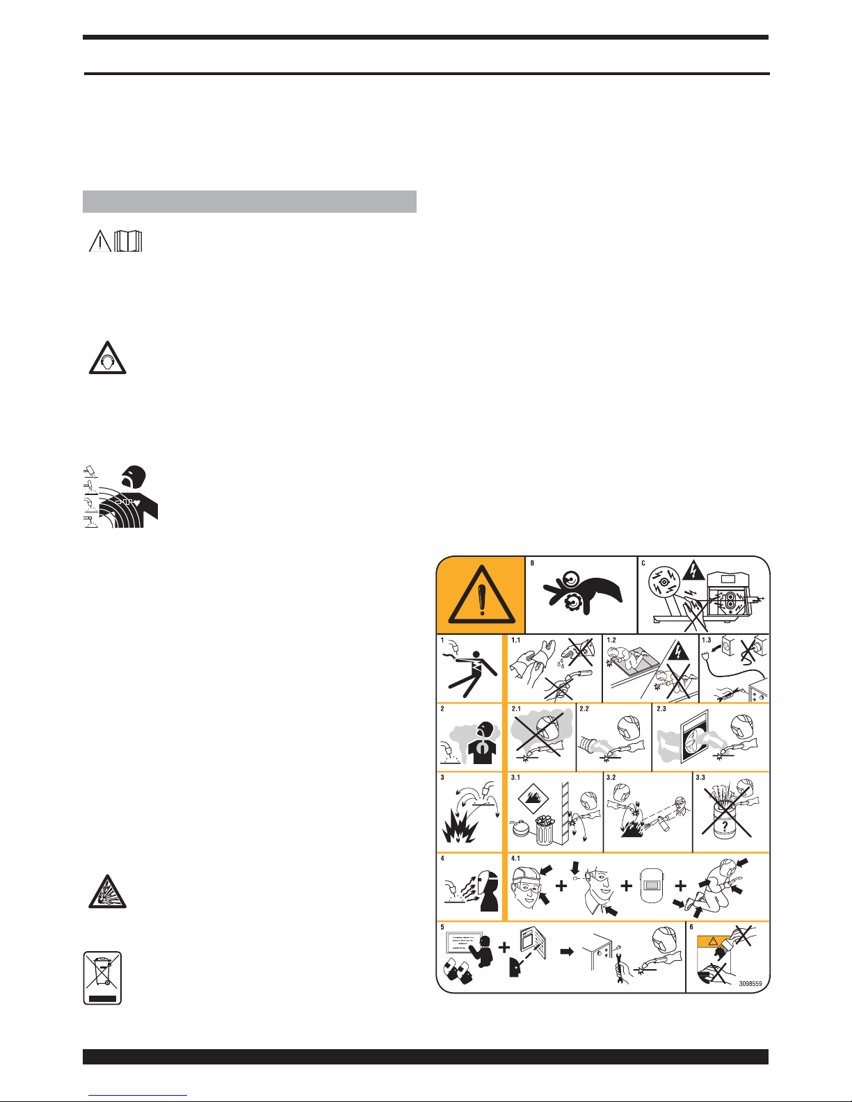
1.1 WARNING LABEL
The following numbered text corresponds to the label
numbered boxes.
B. Drive rolls can injure ngers.
Page 3
3
C. Welding wire and drive parts are at welding volta-
ge during operation - keep hands and metal objects
away.
1 Electric shock from welding electrode or wiring can kill.
1.1 Wear dry insulating gloves. Do not touch electrode
with bare hand. Do not wear wet or damaged gloves.
1.2 Protect yourself from electric shock by insulating
yourself from work and ground.
1.3 Disconnect input plug or power before working on
machine.
2 Breathing welding fumes can be hazardous to your
health.
2.1 Keep your head out of fumes.
2.2 Use forced ventilation or local exhaust to remove
fumes.
2.3 Use ventilating fan to remove fumes.
3 Welding sparks can cause explosion or re.
3.1 Keep ammable materials away from welding.
3.2 Welding sparks can cause res. Have a re extingui-
sher nearby and have a watchperson ready to use it.
3.3 Do not weld on drums or any closed containers.
4 Arc rays can burn eyes and injure skin.
4.1 Wear hat and safety glasses. Use ear protection and
button shirt collar. Use welding helmet with correct
shade of lter. Wear complete body protection.
5 Become trained and read the instructions before
working on the machine or welding.
6 Do not remove or paint over (cover) label.
2 GENERAL DESCRIPTIONS
2.1 SPECIFICATIONS
The machine has been designed and built for welding
ferrous and non-ferrous stud bolts, Ø 3, 4, 5, 6 and 8 mm.
This welding system uses the extremely rapid (2-3 ms)
discharge of a battery of charged capacitors, which allows
the welding of stud bolts with contact point start-up.
2.2 EXPLANATION OF THE TECHNICAL
SPECIFICATIONS LISTED ON THE MACHINE
PLATE
N° Serial number, which must be indicated on any
request regarding the welding machine
1
~
Single-phase transformer-rectier with device
for charging and discharging the capacitors
U0 Secondary open-circuit voltage
E Welding energy
C Capacity value
Uc Voltage adjustable on the capacitors
U1 Rated supply voltage. The machine is set up for
voltages of 120V and 240V with automatic
voltage change.
1-50/60Hz 50- or 60-Hz single-phase power supply
I1 Max Max. absorbed current at the corresponding
supply voltage.
I1 Eff This is the current absorbed considering the duty
cycle at the corresponding input voltage.
IP21S Protection rating for the housing.
Note:
The machine has also been designed for use in
environments with a pollution rating of 3. (See IEC 60664).
2.3 DESCRIPTION OF PROTECTIVE DEVICES
2.3.1 Thermal protection
This machine is protected by a thermostat, which prevents
the machine from operating if the allowable temperatures
are exceeded. Under these conditions the fan keeps
running and the display will show "Warning 08".
3 INSTALLATION
WARNING
See complete listing of safety messages at the beginning
of this manual.
Only skilled personnel should install the machine. All
connections must be carried out according to current
regulations, and in full observance of safety laws.
1. Do not place the welding machine on oor with
inclination greater than 10°.
Air must circulate freely, both incoming and outgoing,
and the welding machine must be protected from entry
by liquids, dirt, metal lings, etc.
2. Make sure that the supply voltage is either 120 volts
and a minimum of 20 amp service or 240 volt and a
minimum of 20 amp service. If connected to a circuit
protected by fuses, use time dely fuse marked "D".
Use a plug Nema type 5-20P for 120 V and make sure
that the "green conductor" of the power supply cable
is connected to the ground or “earth” terminal. Make
sure that the white wire is connected to the W plug
terminal.
Use a plug Nema type 6-20P for 240 V and make sure
that the "green conductor" of the power supply cable
is connected to the ground or “earth” terminal. Make
sure that the white wire is connected to the Y plug
terminal.
The machine must be switched off when changing
the power supply.
3. Pacemaker wearers are prohibited from using the
machine or approach the cables.
4. Fully insert the earth cable plug into the socket B and
turn clockwise.
5. Fully insert the gun plug into the socket C and turn
clockwise.
6. Turn on the welding machine using the E switch.
(start-up and shutdown should not be repeated
frequently, because dissipating the energy contained
in the capacitors may cause overheating and damage).
7. To limit exposure to the magnetic eld, keep the gun
cable on the side of the hand holding it, avoiding
wrapping the cable around.
Page 4

4
3.1 DESCRIPTION OF THE EQUIPMENT
A- Display for the setting and control of welding operations
B- Positive output terminal
C- Negative output terminal
D- Torch trigger connector
E- Main switch
F- Fuse Ø 6.3x32 (delayed type). The equipment is tted
with a 12A-T fuse.
G- Knob for the setting and control of welding operations.
3.2 GUN DESCRIPTION
K- Gun body
L- Grip
M- Control cable
N- Welding current cable
O- Welding command button (works only with the gun
pressed against the sheet metal)
P- Force setting indicator
Q- Force adjustment screw (increases when turned clock
wise)
R- Ring to hold spacer Z
S- Clamp locking ring-nut
T- Safety bellows
U- Holding screws for ring R
V- Screw to adjust stud bolt protrusion
W- Holding nut.
X- Stud bolt gripping clamp
Y- Screw
Z- Spacer
X
M N L
S Z T
R U
O P QK
Fig. 2
X W V
1÷1,5 mm
Y
3.2.1 Preparing the gun
Always use high-quality studs with contact point startup for capacitor discharge welding, which comply with
standards and are made of a metal compatible with the
welding to be done.
Having selected the stud bolt to be welded for type,
diameter, length and material, use and adjust the gripping
clamp according to the corresponding diameter.
A
B C
G
D
E
F
Fig. 1
Page 5
5
Insert the stud bolt in the clamp X so that it is rmly held
in place by the four springs.
Adjust the protrusion of the stud bolt from the front of the
clamp to 1 ÷ 1.5 mm using the screw V, then tighten with
the nut W ( gure 2).
Insert the clamp X into the chuck of the gun ( g. 2), press
until you feel it rest all the way down, and tighten the nut
S using the 17-mm hexagon wrench provided.
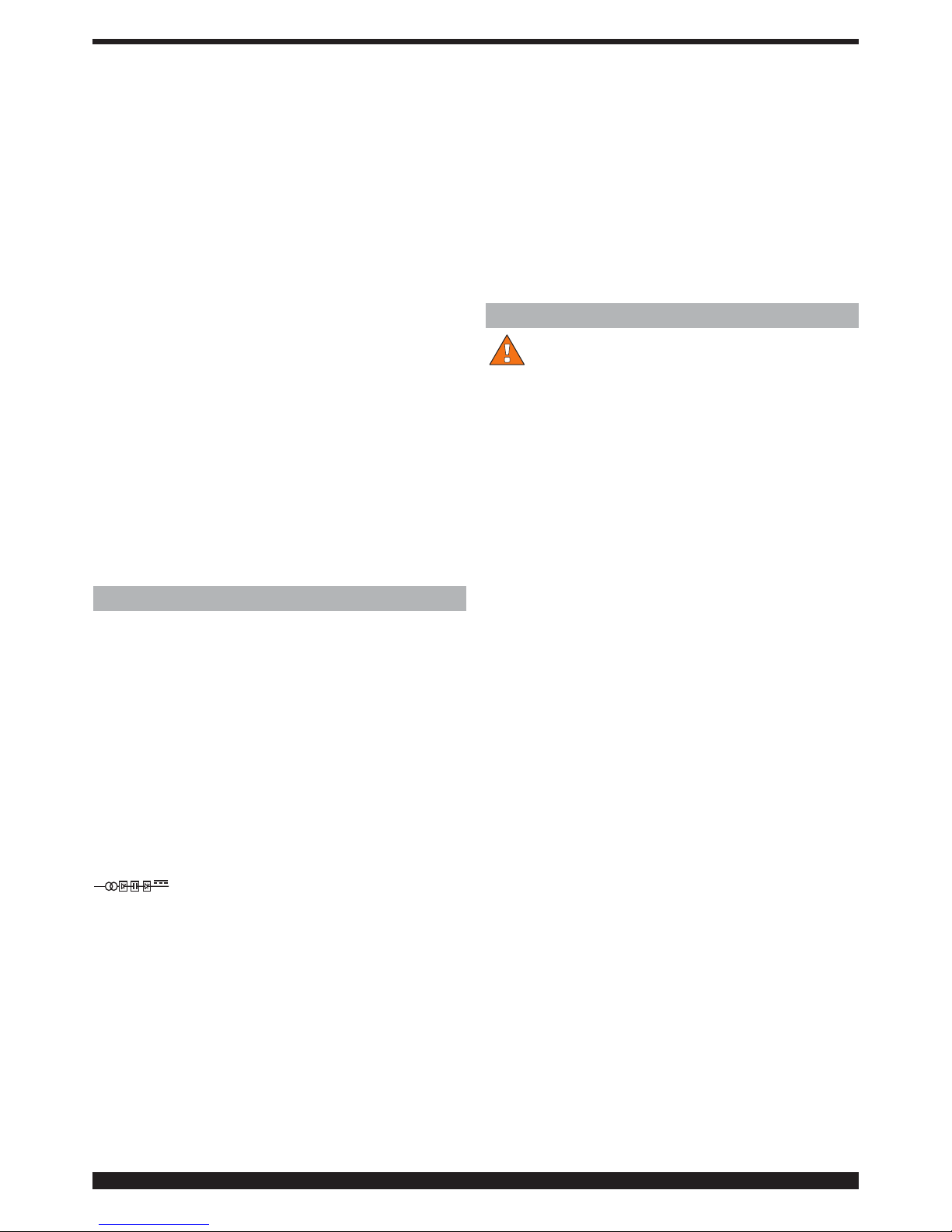
3.3 DESCRIPTION OF FUNCTIONS SHOWN ON THE
DISPLAY A.
When the machine is switched
on, for a few seconds the
display A will show the
machine item number, version
and development date of the
software.
A few seconds later, the following screen will appear on
the display A:
a
b
f
c
d
e
g h
a Stud bolt
b Base material
c Rivet material and dimensions
NOTE: the maximum rivet length that can be used is
30mm (1-1/4”)
d Type of base material
e Indication as to weld quality.
This symbol with the letter Q indicates that the stud
material and the base material that have been selected
are weldable, poorly weldable or non-weldable (See
table 1).
good weldability
poor weldability
non-weldable
f Indications/warnings during the welding phase.
During welding phases these symbols provide
process-related indications:
f
f steadily lit: indicates that the generator is ready
to carry out a welding operation.
f
f steadily lit: indicates that the stud bolt is in
contact with the base material and
the generator is ready to carry out the
welding operation.
f
f ashing: indicates that, after the welding was
completed, the gripping clamp X of
the gun was not removed from the
stud bolt.
f
f ashinge: indicates that, after the welding
was completed, the start button
and microswitch inside the gun
were pressed during charging of the
capacitors.
g Value suggested by the force of the spring inside the
gun (if the force setting is changed, it is recommended
also to change the value indicated on the display so
that in the future this change will remain memorized.
The change from the suggested value will be indicated
by an arrow pointing upward if it is increased or
downward if it is decreased).
h Charge voltage of the capacitors (if the voltage
setting is changed from the suggested value, it will
be indicated by an arrow pointing upward if it is
increased or downward if it is decreased).
During the adjustment, the voltage value will ash to
indicate that the generator is working to reach the
requested value.
Whilst the voltage value is ashing, it is not possible
to perform any welding operation.
3.3.1 SETTINGS
Press the knob G for at least 2 seconds to open the
“Process Params” (Process Parameters) menu.
The following parameters are selectable from this menu:
- Stud Material
- Base material
- Spring Force
- Language
- Measure system
- LCD contrast
- Factory Setup
To access each parameter, select it by turning the knob G
and then press it for less than 2 seconds.
Once you have accessed the parameter, turn the knob G
to make the desired choice and then press it again for less
than 2 seconds to con rm the choice made and go back
to the menu with the list of parameters. To go back to the
initial screen, press the knob G for more than 2 seconds.
Page 6
6
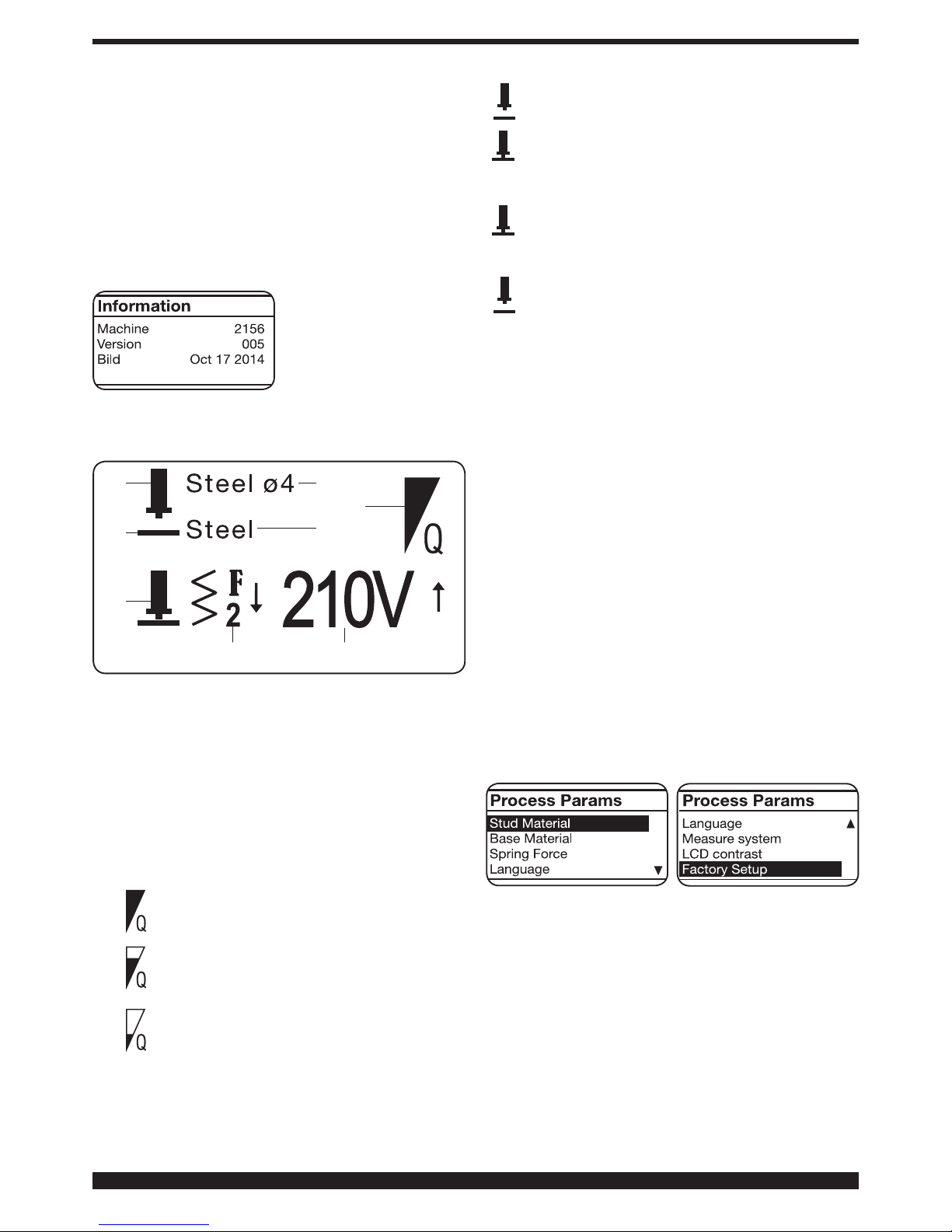
• “Stud Material” parameter.
• “Base Material” parameter.
• “Spring Force” parameter.
The value can be changed by
means of the knob Q.
Note: if the force on the gun
is changed from the proposed value, we recommend
adjusting this value. The
newly changed value will appear on the display and next to
it an arrow pointing downward if the value was decreased
or upward the value was increased.
Based on the choices made, the force and voltage to be
used will be indicated on the display.
It is possible to change the voltage by means of the knob
G, whereas the force displayed on the scale P can be
changed by means of the knob Q.
• “Language” parameter.
• “Measure system” parameter.
• “LCD contrast” parameter.
The value can be changed
from 0 to 100% by means of
the knob G.
This function enables you
to increase or reduce the
brightness of the display A.
• “Factory setup” parameter.
“ON” can be selected by
turning the knob G and
pressing it brie y; the
message “Factory Done”
will appear to con rm that
the reset was successful.
4 OPERATING PRINCIPLE OF WELDING THREADED
STUD BOLTS WITH CONTACT POINT START-UP
(Fig. 3)
The stud bolt is inserted in the clamp X (phase 1), then
positioned and pressed with its start-up contact directly
against the surface of the sheet metal to be welded (phase
2). The spring of the gun presses the stud bolt against
the metal, the start command begins sending current
which melts the start-up contact, and the electrical arc
is propagated along the entire surface of the stud bolt
(phase 4) pushed against the metal surface. The molten
metal solidi es, thereby welding the stud bolt (phase 5).
The gun must be extracted in perfect alignment with the
bolt to avoid deforming the clamp, and thus ensuring its
long life-span (phase 6).
Page 7

7
Stud material
Base metal
Copper plated steel
up to 0.2 C%
Stainless steel
304/316
Al Mg 3 AI Si 12 Al 99,5
Steel up to 0.30 C % A A - - Galvanized steel B B - - Stainless steel 304/316 A A - - Al 99,5 - - A B B
Al Mg 3 - - B A B
Al Si 12 - - B A B
High weldability: A Low weldability: B Not weldable: -
Tab. 1
Fig. 3
1 2 3 4 5
5 WELDABILITY OF TYPICAL STUD BOLT/BASE
METAL COM BINATIONS FOR CAPACITOR
DISCHARGE WELDING. (Table 1)
It is important to pay careful attention to the resistance and
deformity at the welding point between the stud bolt and base
metal. In the case of steel, you must pay particular attention
to brittleness. The material and resistance of the stud bolt
have limited tolerance; the carbon content in steel threaded
stud bolts must be < 0.20%.
The surface of the base metal must be clean. Layers
of paint, rust, waste, grease and non-weldable metal
coatings must be removed from the welding area. This
must be done using appropriate means. Base metals with
layers of waste and rust must be cleaned thoroughly.
6 WELDING
This technology makes it possible to weld stud bolts on
clean, but not oxidized, surfaces of mild steel, galvanized
steel, stainless steel, aluminum and brass.
The rapidity of the process does not alter the surfaces on the
side opposite from the welding. Welding is not possible on
case-hardened steel, oxidized or painted metal.
Before beginning production it is essential to carry out a
few test welds to determine the proper setting of the power
source and gun (spring force), proceeding as follows:
• Insert the chosen stud bolt in the clamp X (previously
adjusted as described in Fig. 2).
• Arrange the base sheet metal in conditions identical to
those that will be used for the job in terms of thickness,
earth connection area, size of the workpiece, material
quality.
• The terminals of the earth cable should be placed
symmetrically, and as close as possible to the welding
point.
• Activate the power source by means of the lighted
switch E.
• Hold the gun and place the stud on the welding spot,
avoiding to give blows, consequently damaging the
striking tip of the stud. Press the trigger O and, holding it
pressed, push the gun evenly and not quickly. Once the
right pressure is reached, the weld will be automatically
activated. If the surface of the material on which the stud
bolt is to be welded is at, we recommend mounting the
three spacers Z after rst unscrewing the screws Y
• In this case it is recommended to push the gun until the
three spacers are in touch with the piece and then press
the trigger to activate the welding.
These procedures are required to obtain the same
pressure of the stud on the base material and
consequently a higher quality of the weld.
• The voltage and force values recommended on the display
are intended as a starting point for calculating the correct
power source setting and for calibrating gun force.
These values have been tested on samples of “base
materials” 0.079" (2 mm) thick for steel and stainless steel
and 0.047" (1.2 mm) thick for aluminium.
Page 8
8
• Carry out a few welds, adjusting the voltage using the knob
G, and the force of the gun using the setting knob Q, until
the welding is perfect.
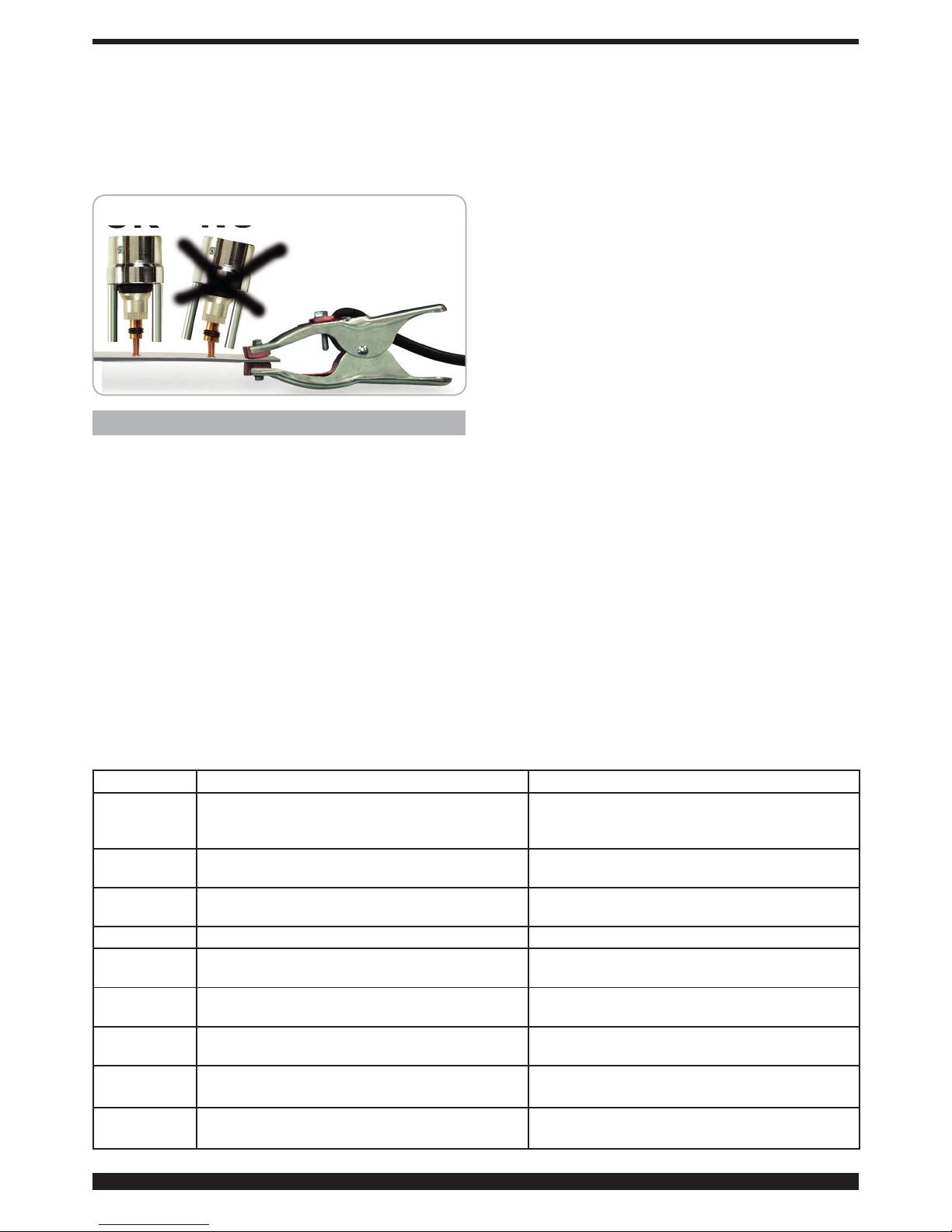
• The gun should be removed keeping it perfectly aligned
with the bolt, to avoid deforming the clamp (Fig4).
• Do not make welds to welded stud bolts.
OK
NO
Fig. 4
7 MAINTENANCE
7.1 ROUTINE
Keep all instructions and gures on the welding machine
clear and legible.
The mains cable and welding cables must be insulated
and in perfect condition; be careful with the tips, which ex:
near the connection terminals, earth clamps and gun input.
Keep the welding current connectors to sockets B and C
clean and rmly tightened (see Fig. 1)
The terminals for connecting to the base metal must
make good contact to avoid overheating, sparks, uneven
current circulation, damage to the components where the
pins are welded, and welding of uneven quality.
Prevent dirt, dust and lings from getting into the welding
machine.
Always make sure the cooling air circulates freely.
Make sure that the fan functions properly.
Make sure that the clamps hold the stud bolts rmly, with
all contact springs.
The clamp must slide freely throughout its length, without
changes due to friction or foreign matter.
7.2 SPECIAL
Only quali ed personnel should perform maintenance.
Some functional errors are highlighted by the appearance
of an error code on the display A.
Wait at least 5 minutes after shutting off the switch E
before opening the welding machine, and unplug the plug
from the power socket.
Use a volt meter to make sure that the capacitors are
discharged.
Carefully remove any dust, metal fragments and lings
from the machine using compressed air to avoid damaging
or projecting metal fragments onto the electronic or
electrical parts.
Make sure that all connectors are fully inserted.
Make sure that all welding circuit terminals are rmly
tightened.
After making a repair, make sure to rearrange the wiring
so that there is secure insulation between the primary and
secondary sides of the machine. Do not allow wires to
come into contact with moving parts or those that heat
up during operation. Reassemble all of the clamps as they
were on the original machine, to prevent an accidental
connection between the primary and secondary circuits if
a conductor should break or disconnect.
Also remount the screws with geared washers as on the
original equipment.
Error code Problem Solution
WARNING 1 It means that the gun start button and microswitch
are pressed at the moment the generator is turned
on.
Release the start button.
ERROR 2 It means that the relay RL1 is faulty. Power circuit fault.
Contact the technical support service.
ERROR 3 It means that the relay RL1 is faulty. Power circuit fault.
Contact the technical support service.
ERROR 4 It means that the SCR has short circuited Contact the technical support service.
ERROR 5 It means that there is a fault in the capacitor
charging circuit
Contact the technical support service.
ERROR 7 It means that there is a fault in the capacitor
charging circuit
Contact the technical support service.
WARNING TH
It means that the thermal protector has tripped.
Wait a few minutes without turning off the welding
machine.
ERROR 9
It means that there is a fault in the circuit that
measures the voltage across the capacitors.
Power circuit fault.
Contact the technical support service.
ERROR 10
It means that there is a short circuit in the
capacitor discharging circuit.
Power circuit fault.
Contact the technical support service.
Page 9
9
MANUEL D’INSTRUCTIONS POUR POSTE A SOUDER A FIL
IMPORTANT: AVANT LA MISE EN MARCHE DE LA MA-
CHINE, LIRE CE MANUEL ET LE GARDER, PENDANT
TOUTE LA VIE OPÉRATIONNELLE, DANS UN ENDROIT
CONNU PAR LES DIFFÉRENTES PERSONNES INTÉRESSÉES. CETTE MACHINE NE DOIT ÊTRE UTILISÉE
QUE POUR DES OPÉRATIONS DE SOUDURE.
1 PRÉCAUTIONS DE SÉCURITÉ
LA SOUDURE ET LE DÉCOUPAGE À L’ARC
PEUVENT ÊTRE NUISIBLES À VOUS ET AUX
AUTRES. L’utilisateur doit pourtant connaître les risques,
résumés ci-dessous, liés aux opérations de soudure. Pour
des informations plus détaillées, demander le manuel
code.3.300758
BRUIT
Cette machine ne produit pas elle-même des bruits
supérieurs à 80 dB. Le procédé de découpage au
plasma/soudure peut produire des niveaux de bruit
supérieurs à cette limite; les utilisateurs devront donc mette
en oeuvre les précautions prévues par la loi.
CHAMPS ELECTROMAGNETIQUES- Peuvent être dangereux.
· Le courant électrique traversant n’importe
quel conducteur produit des champs électromagnétiques (EMF). Le courant de soudure ou de découpe produisent des champs
électromagnétiques autour des câbles ou
des générateurs.
• Les champs magnétiques provoqués par des courants
élevés peuvent interférer avec le fonctionnement des stimulateurs cardiaques. Aux porteurs de stimulateurs
cardiaques il est défendu d'utiliser la machine ou de
s'approcher des câbles.
• L’ exposition aux champs électromagnétiques de soudure ou de découpe peut produire des effets inconnus
sur la santé.
Pour reduire les risques provoqués par l’exposition aux
champs électromagnétiques chaque opérateur doit
suivre les procédures suivantes:
- Vérier que le câble de masse et de la pince porte
électrode ou de la torche restent disposés côte à côte.
Si possible, il faut les xer ensemble avec du ruban.
- Ne pas enrouler les câbles de masse et de la pince
porte-électrode ou de la torche autour du corps.
- Ne jamais rester entre le câble de masse et le câble
de la pince porte-électrode ou de la torche. Si le câble
de masse se trouve à droite de l’opérateur, le câble de
la pince porte-électrode ou de la torche doit être égale
ment à droite.
- Connecter le câble de masse à la pièce à usiner aussi
proche que possible de la zone de soudure ou de découpe.
- Ne pas travailler près du générateur.
EXPLOSIONS
· Ne pas souder à proximité de récipients sous
pression ou en présence de poussières, gaz ou
vapeurs explosifs. Manier avec soin les bouteilles
et les détendeurs de pression utilisés dans les opérations
de soudure.
COMPATIBILITE ELECTROMAGNETIQUE
Cette machine est construite en conformité aux indications contenues dans la norme harmonisée IEC 6097410(Cl. A) et ne doit être utilisée que pour des buts professionnels dans un milieu industriel. En fait, il peut y avoir
des difcultés potentielles dans l’assurance de la compatibilité électromagnétique dans un milieu différent de celui
industriel.
ÉLIMINATION D’ÉQUIPEMENTS ÉLECTRIQUES
ET ÉLECTRONIQUES
Ne pas éliminer les déchets d’équipements élec-
triques et électroniques avec les ordures ménagères! Une fois leur cycle de vie terminé, les équipements électriques et électroniques doivent être collectés
séparément et conférés à une usine de recyclage. Nous
recommandons aux propriétaires des équipements de
s’informer auprès de notre représentant local au sujet
des systèmes de collecte agréés.
Des précautions supplémentaires sont à respecter
lorsque l'on travaille en hauteur.
COMPATIBILITE ELECTROMAGNETIQUE
Au Canada, la classication des EMC ne s'applique pas
aux postes de soudage à l'arc.
NORMES DE SECURITE
Pour fournir les conditions et recommandations mini-
males an de protéger les personnes qui travaillent dans
un environnement concerné par le soudage, le coupage
et les techniques connexes, il faut se référer à la norme
CA N/C SA -W117. 2.
EN CAS DE MAUVAIS FONCTIONNEMENT, DEMANDER
L’ASSISTANCE DE PERSONNEL QUALIFIÉ.
1.1 PLAQUETTE DES AVERTISSEMENTS
Le texte numéroté suivant correspond aux cases numérotées de la plaquette.
B. Les galets entraînement l peuvent blesser les mains.
C. Le l de soudure et le groupe entraînement l sont
sous tension pendant le soudage. Ne pas approcher
les mains ni des objets métalliques.
1. Les décharges électriques provoquées par l’élec-
trode le câble peuvent être mortelles. Se protéger de
manière adéquate contre les décharges électriques.
1.1 Porter des gants isolants. Ne pas toucher l’électrode
avec les mains nues. Ne jamais porter des gants humides ou endommagés.
1.2 S’assurer d’être isolés de la pièce à souder et du sol
1.3 Débrancher la che du cordon d’alimentation avant
de travailler sur la machine.
2. L’inhalation des exhalations produites par la soudure
peut être nuisible pour la santé.
2.1 Tenir la tête à l’écart des exhalations.
2.2 Utiliser un système de ventilation forcée ou de déchar-
gement des locaux pour éliminer toute exhalaison.
2.3 Utiliser un ventilateur d’aspiration pour éliminer les
exhalations.
3. Les étincelles provoquées par la soudure peuvent
causer des explosions ou des incendies.
Page 10

10
3.1 Tenir les matières inammables à l’écart de la zone
de soudure.
3.2 Les étincelles provoquées par la soudure peuvent causer
des incendies. Maintenir un extincteur à proximité et faire
en sorte qu’une personne soit toujours prête à l’utiliser.
3.3 Ne jamais souder des récipients fermés.
4. Les rayons de l’arc peuvent irriter les yeux et brûler la peau.
4.1 Porter un casque et des lunettes de sécurité. Utiliser des dispositifs de protection adéquats pour les
oreilles et des blouses avec col boutonné. Utiliser des
masques et casques de soudeur avec ltres de degré approprié. Porter des équipements de protection
complets pour le corps.
5. Lire la notice d’instruction avant d’utiliser la machine
ou avant d’effectuer toute opération.
6. Ne pas enlever ni couvrir les étiquettes d’avertissement.
2 DESCRIPTIONS GENERALES
2.1 SPECIFICATIONS
La machine a été conçue et réalisée pour la soudure de
goujons letés Ø 3, 4, 5, 6 et 8 mm, ferreux et non ferreux.
Ce système de soudure utilise la décharge extrêmement
rapide (2-3 ms) d'une batterie de condensateurs permettant
de souder les goujons letés avec pointe d'amorçage.
2.2 EXPLICATION DES DONNÉES TECHNIQUES
N° Numéro matricule à citer toujours pour toute
question concernant le poste à souder.
1
~
Transformateur monophasé-redresseur avec
dispositif pour la charge et la décharge de
condensateurs
U0 Tension à vide secondaire
E Energie de soudure
C Valeur de la capacité
Uc Tension réglable sur les condensateurs
U1 Tension nominale d'alimentation. La machine
est prévue pour les tensions 120V et 240V
avec sélection de tension automatique.
1-50/60Hz Alimentation monophasée 50 ou bien 60Hz
I1max Courant maxi absorbé à la correspondante
tension d'alimentation
I1 eff C'est la valerur maximale du courant effectif
absorbé en considérant le facteur de marche.
IP21S Degré de protection estimée pour le logement.
REMARQUES :
En outre, la machine est indiquée pour opérer dans des
milieux avec degré de pollution 3. (Voir IEC 60664).
2.3 DESCRIPTION DES PROTECTIONS
2.3.1 Protection thermique
Cette machine est protégée par un thermostat empêchant
le fonctionnement de la machine lors du dépassement des
températures admises. Dans ces conditions le ventilateur
continue à fonctionner et le display afchera le code
d'erreur "Warning 8".
3 INSTALLATION
WARNING
Voir la liste complète des messages de sécurité au
début de ce manuel.
Seules les personnes qualiées sont autorisées à installer
la machine. Tous les branchements doivent être réalisés
selon la réglementation en vigueur et conformément aux
lois sur la sécurité.
1 Ne placez pas le poste à souder sur le sol avec une
inclinaison de plus de 10°.
L'air doit circuler librement, en entrée et en sortie ,
et la machine de soudage doit être protégée pour
empêcher la pénétration de liquides, de saleté, de
dépôts métalliques, etc.
2. Assurez-vous que la tension d'alimentation est de 120
Volts et de 20 ampères minimum ou de 240 Volts et 20
ampères minimum. En cas de connexion à un circuit
protégé par des fusibles, utilisez des fusibles à action
retardée marqués « D ».
Utilisez une prise Nema type 5-20P pour 120 V et
assurez-vous que le « l conducteur vert » du câble
d'alimentation est relié à la masse ou « borne de mise
à la terre ». Assurez-vous que le l blanc est connecté
à la borne de connecteur W.
Utilisez une prise Nema type 6-20P pour 240 V et
assurez-vous que le « l conducteur vert » du câble
d'alimentation est relié à la masse ou « borne de mise
à la terre ». Assurez-vous que le l blanc est connecté
à la borne de connecteur Y.
La sélection de l'alimentation doit être opérée avec
la machine arrêtée.
3. Les porteurs de stimulateurs cardiaques ne doivent
ni utiliser la machine ni s'approcher des câbles.
4. Insérez complètement la che du câble de terre dans la
prise B et tournez dans le sens horaire.
5. Insérez complètement la che du câble de terre dans la
Page 11

11
prise C et tournez dans le sens horaire.
6. Allumez le poste de soudage en utilisant le commuta-
teur E. Évitez d'allumer et d'éteindre le poste trop
fréquemment car la dissipation d'énergie contenue
dans les condensateurs peut provoquer une surchauffe
et entraîner des dommages.
7. Pour limiter l'exposition au champ magnétique, gardez
le câble du pistolet sur le côté de la main en le tenant
et en évitant d'envelopper le câble autour.
3.1 DESCRIPTION OF THE EQUIPMENT
A- Display for the setting and control of welding operations
B- Positive output terminal
C- Negative output terminal
D- Torch trigger connector
E- Main switch
F- Fuse Ø 6.3x32 (delayed type). The equipment is tted
with a 12A-T fuse.
G- Knob for the setting and control of welding operations.
3.2 DESCRIPTION DU PISTOLET
K- Corps du pistolet
L- Manche
M- Câble de commande
N- Câble de courant de soudage
O- Bouton de commande de soudage (ne fonctionne que
lorsque le pistolet est appuyé contre la tôle)
P- Indicateur de réglage de la force
Q- Vis de réglage de la force (augmente en la tournant
dans le sens horaire)
R- Bague pour tenir l'entretoise Z
S- Écrou à œil de blocage de la pince
T- Souf et de sécurité
U- Vis de xation pour bague R
V- Vis pour régler la saillie du goujon prisonnier
W- Écrou de xation.
X- Pince de serrage du goujon prisonnier
Y- Vis
Z- Entretoise
X
M N L
S Z T
R U
O P QK
Fig. 2
X W V
1÷1,5 mm
Y
A
B C
G
D
E
F
Fig. 1
Page 12

12
3.2.1 Préparation du pistolet
Utilisez toujours des prisonniers de haute qualité
avec démarrage au point de contact pour soudage
à accumulation d'énergie électrostatique, en métal
compatible avec la soudure à réaliser et conformes aux
normes. Après avoir sélectionné le goujon prisonnier à
souder en fonction du type, du diamètre, de la longueur
et du matériau, utilisez et réglez la pince de serrage en
fonction du diamètre correspondant.
Insérez le goujon prisonnier dans la pince X de sorte qu'il
soit fermement maintenu en place par les quatre ressorts.
Ajustez la saillie du goujon prisonnier sur 1 ÷ 1,5 mm à
partir de l'avant de la pince en utilisant la vis V, puis serrez
avec l'écrou W (gure 2).
Insérez la pince X dans le mandrin du pistolet (g. 2),
appuyez dessus jusqu'à ce que vous sentiez qu'elle
est bien au fond, puis serrez l'écrou S à l'aide de la clé
hexagonale de 17 mm qui est fournie.
3.3 DESCRIPTION DES FONCTIONS AFFICHÉES SUR
L'ÉCRAN A.
Lors de l'allumage de
l'appareil, l'écran A afche
pendant quelques instants : la
référence de l'appareil, sa
version et la date de
développement du logiciel.
Après quelques secondes, apparaît sur l'écran A l'afchage
suivant :
a
b
f
c
d
e
g h
a Prisonnier
b Matériau de base
c Matériau du rivet et dimensions
REMARQUE : la longueur maximale du rivet pouvant
être utilisé est de 30 mm (1-1/4”)
d Type de matériau de base
e Indications sur la qualité de la soudure.
Ce symbole avec la lettre Q indique que les matériaux
du prisonnier et du matériau de base qui ont été choisi
sont soudables, peu soudables ou non-soudables
(Cf. tableau 1).
Bonne soudabilité
Faible soudabilité
non soudables
f Indications/avertissements durant la phase de
soudage. Lors des phases de soudage, ces symboles
apportent des indications concernant le processus:
f
f xe: Indique que le générateur est
prêt à exécuter une soudure.
f
f xe: Indique que le prisonnier est en
contact avec le matériau de base
et que le générateur est prêt à
exécuter la soudure.
f
f clignotant: Indique qu'après avoir exécuté la
soudure, la pince X du pistolet n'a
pas été dégagée du prisonnier.
f
f clignotant: Indique qu'après avoir exécuté la
soudure, le bouton de démarrage
et le micro-rupteur à l'intérieur
du pistolet sont maintenus
enfoncé pendant la charge des
condensateurs.
g Valeur suggérée de la force du ressort situé à l'intérieur
du pistolet (s'il y a une modication par rapport
au réglage de la force, il est conseillé de modier
également la valeur indiquée sur l'écran de façon à
ce qu'à l'avenir cette modication reste en mémoire.
La modication par rapport à la valeur suggérée sera
indiquée par une èche tournée vers le haut si elle est
augmentée ou par une èche tournée vers le bas si
elle est baissée)
h Tension de charge des condensateurs (la modication
du réglage de la tension par rapport à la valeur
suggérée sera indiquée par une èche tournée vers le
haut si elle est augmentée ou par une èche tournée
vers le bas si elle est baissée).
Lors du réglage, la valeur de la tension clignote et
indique que le générateur travaille pour arriver à la
valeur requise.
Lorsque la valeur de la tension clignote, il n'est pas
possible de procéder au soudage.
3.3.1 RÉGLAGES
Appuyez pendant au moins 2 secondes sur le bouton G
pour entrer dans le menu « Process Params » (Paramètres
de fonctionnement).
Dans ce menu sont disponibles les paramètres suivants:
- Stud Material (matériau prisonnier)
- Base material (matériau de base)
- Spring Force (force du ressort)
- Language (langue)
- Measure system (système de mesure)
Page 13

13
- LCD contrast (contraste écran à cristaux liquides)
- Factory Setup (réglage usine)
Pour entrer à l'intérieur de chaque paramètre,
sélectionnez-le en tournant le bouton G, puis appuyez
dessus pendant moins de 2 secondes. Une fois dans le
paramètre, tournez le bouton G pour faire votre choix puis
appuyez à nouveau dessus pendant moins de 2 secondes
pour valider l'option et retourner au menu de la liste des
paramètres. Pour revenir à la page initiale, appuyez sur le
bouton G pendant plus de 2 secondes.
• Paramètre « Stud Material » (Matériau prisonnier)
• Paramètre « Base Material » (Matériau de base)
• Paramètre « Spring Force » (Force du ressort)
Il est possible de changer la
valeur par le biais du bouton
Q.
Remarque: au cas où la
tension serait modiée sur
le pistolet par rapport à la
valeur proposée, nous vous suggérons de modier cette
valeur. La nouvelle valeur modiée apparaîtra sur l'écran
avec à côté une èche tournée vers le bas si la valeur a été
baissée et une èche tournée vers le haut si la valeur a été
augmentée.
En fonction des options choisies sur l'écran, la tension et la
force à utiliser sont indiquées.
Par le biais du bouton G il est possible de modier la ten-
sion tandis qu'avec le bouton Q, situé sur le pistolet, il est
possible de modier la force qui est afchée sur l'échelle P.
• Paramètre « Language » (langue)
• Paramètre « Measure system » (Système de mesure)
• Paramètre « LCD contrast » (Contraste de l'écran à
cristaux liquides)
Il est possible de changer la
valeur de 0 à 100% par le
biais du bouton G.
Cette fonction permet de
jouer sur la luminosité de
l'écran A.
• Paramètre « Factory setup » (réglages d'usine)
Par le biais du bouton G il
est possible de sélectionner
ON et en appuyant
brièvement dessus s'afche
le message Factory Done
qui indique que la remise à
zéro a bien été faite.
4 PRINCIPE DE FONCTIONNEMENT DE LA
SOUDURE DE GOUJONS FILETES AVEC POINTE
D'AMORCAGE (Fig. 3)
Le goujon est inséré dans la pince X (phase 1) et est ensuite
positionné et appuyé avec son amorçage directement
sur la surface de la tôle à souder (phase 2). Le ressort du
pistolet appuie le goujon contre le métal, la commande de
start fait commencer le passage de courant qui vaporise
l'amorçage et l'arc électrique se propage sur l'entière
surface du goujon (phase 3) qui est poussé sur la surface
métallique. Le métal fondu solidie en soudant le goujon
(phase 4).
L'extraction du pistolet doit être parfaitement alignée
avec le goujon an de ne pas déformer la pince et assurer
ainsi une longue durée (phase 5).
Page 14

14
5 SOUDABILITE DE COMBINAISONS TYPIQUES
GOUJON ET METAL DE BASE POUR SOUDURE
PAR DECHARE DE CONDENSATEURS. (Tableau 1)
Il est important d'étudier carrément la résistance et la
déformation dans le point de soudure entre goujon et métal
de base. Dans le cas de l'acier, il faut prêter une attention
particulière à la fragilité causée par le durcissement. La
matière et la résistance du goujon ont une tolérance réduite;
la teneur en carbone des goujons letés doit être < 0,20%.
La surface du métal de base doit être propre. Les
éventuelles couches de vernis, rouille, laitiers, graisse
et les revêtements de métaux non soudables doivent
être enlevés de la zone de soudure à l'aide des moyens
appropriés. Les métaux de base avec couches de laitiers
et rouille doivent être parfaitement nettoyés.
6 SOUDURE
Cette technologie permet de souder les goujons letés sur
des surfaces propres, mais non oxydées, d'acier doux, acier
galvanisé, acier inox, aluminium et laiton.
La rapidité du procédé n'altère pas les surfaces à l'envers de
la soudure. La soudure n'est pas possible sur acier trempé,
métal oxydé ou verni.
Avant de commencer la production, il est indispensable
d'effectuer quelques soudures d'essai pour déterminer le
correct réglage du générateur et l'étalonnage du pistolet
(force du ressort) en exécutant les opérations suivantes:
• Insérer le goujon choisi dans la pince X (réglée au préalable
comme décrit dans la Fig. 2)
• Ranger la tôle de base dans des conditions identiques aux
futures conditions de travail pour ce qui de l'épaisseur, aire
des raccordements de masse, dimensions de la pièce,
qualité de la matière.
• Les bornes du câble de masse doivent être placées en
mode symétrique et aussi proches que possible du point
de soudure.
• Mettre en service le générateur à l'aide de l'interrupteur
lumineux E.
• Saisir le pistolet et positionner le prisonnier sur le point
de soudure en évitant de porter des coups pour ne pas
endommager l’amorçage du prisonnier. Appuyer sur la
touche O et, la tenant enfoncée, pousser le pistolet de
manière uniforme et non rapide. Une fois que la pression
correcte a été atteinte, la soudure partira automatiquement.
Si la surface de la matière où le goujon doit être soudé est
plate, il est conseillé de monter trois entretoises Z après
avoir desserré les vis Y.
• Dans ce cas il est conseillé de pousser le pistolet
jusqu’à ce que les trois entretoises battent sur la pièce,
et puis d’appuyer la touche pour activer la soudure.
Ces procédures sont nécessaires pour avoir la même
pression du prisonnier sur le matériel de base et,
par conséquent, une amélioration de la qualité de la
soudure.
• Les valeurs de tension et de force, conseillées à l'écran,
sont à considérer comme base de départ pour déterminer
le bon réglage du générateur et de l'étalonnage de la force
du pistolet.
Ces valeurs ont été expérimentales sur des échantillons de
Métal goujons
Métal de base
Acier 0,2 C
cuivré
inox
304/316
Al Mg 3 AI Si 12 Al 99,5
Acier jusqu'à 0,30 C % A A - - Acier zingué B B - - Acier inoxydable 304/316 A A - - Al 99,5 - - A B B
Al Mg 3 - - B A B
Al Si 12 - - B A B
Bonne soudabilité: A Basse soudabilité: B Non soudables: -
Tab. 1
Fig. 3
1 2 3 4 5
Page 15

15
« matériau de base » d'une épaisseur de 2 mm (0.079")
pour l'acier et l'acier inoxydable et d'une épaisseur de 1,2
mm (0.047") pour l'aluminium..
• Exécuter quelques soudures en réglant la tension à l'aide
des bouton G et la force du pistolet avec le réglage Q
jusqu'à obtenir des soudures parfaites.
Le pistolet doit être extrait en le gardant parfaitement aligné
avec le goujon a n de ne pas déformer la pince (Fig. 4).
• Pas de soudure sur les goujons letés déjà soudé.
OK
NO
Fig. 4
7 ENTRETIEN
7.1 ORDINAIRE
Conserver les indications et les gures sur le poste à
souder bien lisibles et claires.
Le câble de réseau et les câbles de soudure doivent être
isolés et en conditions parfaites; prêter attention aux
points où ils subissent des exions, notamment près
des bornes de raccordement, des pinces de masse et à
l'entrée dans le pistolet.
Garder les connecteurs du courant de soudure aux prises
B et C propres et bien serrés. (voir Fig. 1)
Les bornes pour le raccordement au métal de base doivent
faire un bon contact a n d'éviter surchauffes, étincelles,
circulation non balancée du courant, endommagements
au composant où les goujons doivent être soudés et
soudures de qualité non constante.
Empêcher l'entrée de saleté, poussière et limaille à
l'intérieur du poste à souder.
Garantir toujours la circulation de l'air de refroidissement.
Contrôler que le ventilateur fonctionne régulièrement.
Véri er que les pinces serrent bien les goujons avec tous
les ressorts de contact.
Le mandrin porte-pinces doit glisser sans contrainte tout
au long de sa course sans variations dues à frottements
ou corps étrangers.
7.2 EXTRAORDINAIRE
L'entretien doit être exécuté par du personnel quali é.
Certaines anomalies de fonctionnement sont mises en
évidence par l'af chage d'un code d'erreur sur le display A.
vant d'ouvrir le poste à souder attendre au moins 5
minutes après avoir relâché l'interrupteur E et en outre
débrancher la che de la prise d'alimentation.
Contrôler, à l'aide d'un voltmètre, que les condensateurs
sont chargés.
Enlever poussière, fragments et limailles métalliques de
la machine avec soin en utilisant air comprimé a n de ne
pas endommager ou projeter des fragments métalliques
sur les pièces électroniques ou électriques.
Véri er que tous les connecteurs sont bien enfoncés.
Véri er que tous les terminaux du circuit de soudure sont
bien serrés.
Après l'exécution d'un dépannage, veiller à ranger le
câblage de façon à ce qu'il y ait une isolation sûre entre le
côté primaire et le côté secondaire de la machine. Eviter
que les ls puissent entrer en contact avec des pièces
en mouvement ou des pièces se réchauffant pendant le
fonctionnement. Remonter tous les colliers comme sur
la machine d'origine de façon à éviter que, en cas de
rupture ou débranchement accidentel d'un conducteur,
il n'y ait aucune liason entre le primaire et le secondaire.
En outre remonter les vis avec les rondelles dentelées
comme sur la machine d'origine.
Code d'erreur Anomalie Solution
WARNING 1 Indique que le bouton et le microrupteur du pistolet
sont enfoncés au moment où le générateur se
met en marche.
Désarmez le bouton de démarrage.
ERROR 2 Indique que le relais RL1 est défectueux. Circuit de puissance défectueux.
Contactez le service d'assistance
ERROR 3 Indique que le relais RL1 est défectueux. Circuit de puissance défectueux.
Contactez le service d'assistance
ERROR 4 Indique que l'SCR est en court-circuit. Contactez le service d'assistance
ERROR 5 Indique qu'il y a un défaut dans le circuit de
charge des condensateurs
Contactez le service d'assistance
ERROR 7 Indique qu'il y a un défaut dans le circuit de
charge des condensateurs
Contactez le service d'assistance
WARNING TH
Indique que la protec on thermique s'est
déclenchée.
Il faut a endre quelques minutes sans éteindre le
poste de soudage.
ERROR 9
Indique qu'il y a un défaut dans le circuit
qui mesure la tension aux extrémités des
condensateurs.
Circuit de puissance défectueux.
Contactez le service d'assistance
ERROR 10
Indique qu'il y a un court-circuit dans le circuit
de décharge des condensateurs.
Circuit de puissance défectueux.
Contactez le service d'assistance
Page 16

16
IMPORTANTE: ANTES DE LA PUESTA EN FUNCIONAMIENTO DEL APARATO, LEER EL CONTENIDO DE ESTE
MANUAL Y CONSERVARLO, DURANTE TODA LA VIDA
OPERATIVA, EN UN SITIO CONOCIDO POR LOS INTERESADOS. ESTE APARATO DEBERÁ SER UTILIZADO
EXCLUSIVAMENTE PARA OPERACIONES DE SOLDADURA.
1 PRECAUCIONES DE SEGURIDAD
LA SOLDADURA Y EL CORTE DE ARCO PUE-
DEN SER NOCIVOS PARA USTEDES Y PARA
LOS DEMÁS, por lo que el utilizador deberá ser informado de los riesgos, resumidos a continuación, que derivan
de las operaciones de soldadura. Para informaciones
más detalladas, pedir el manual cod.3.300.758
RUIDO
Este aparato de por sí no produce ruidos superiores a los 80dB. El procedimiento de corte plasma/
soldadura podría producir niveles de ruido superiores a tal límite; por consiguiente, los utilizadores deberán poner en practica las precauciones previstas por la
ley.
CAMPOS ELECTROMAGNÉTICOS- Pueden ser dañosos.
• La corriente eléctrica que atraviesa cualquier conductor produce campos electromagnéticos (EMF). La corriente de soldadura o de corte genera campos
electromagnéticos alrededor de los cables y
generadores.
• Los campos magnéticos derivados de corrientes elevadas pueden incidir en el funcionamiento del pacemaker.
A los portadores de pace maker está prohibido usar la
máquina o acercarse a los cables.
• La exposición a los campos electromagnéticos de la
soldadura o del corte podrían tener efectos desconocidos sobre la salud.
Cada operador, para reducir los riesgos derivados de la
exposición a los campos electromagnéticos, tiene que
atenerse a los siguientes procedimientos:
- Colocar el cable de masa y de la pinza portaelectrodo
o de la antorcha de manera que permanezcan anqueados. Si posible, jarlos junto con cinta adhesiva.
- No envolver los cables de masa y de la pinza portaelectrodo o de la antorcha alrededor del cuerpo.
- Nunca permanecer entre el cable de masa y el de la
pinza portaelectrodo o de la antorcha. Si el cable de
masa se encuentra a la derecha del operador también
el de la pinza portaelectrodo o de la antorcha tienen
que quedar al mismo lado.
- Conectar el cable de masa a la pieza en tratamiento lo
más cerca posible a la zona de soldadura o de corte.
- No trabajar cerca del generador.
EXPLOSIONES
• No soldar en proximidad de recipientes a presión o en presencia de polvo, gas o vapores ex-
plosivos. Manejar con cuidado las bombonas y
los reguladores de presión utilizados en las operaciones
de soldadura.
COMPATIBILIDAD ELECTROMAGNÉTICA
Este aparato se ha construido de conformidad a las indicaciones contenidas en la norma armonizada IEC 6097410 (Cl. A) y se deberá usar solo de forma profesional
en un ambiente industrial. En efecto, podrían presentarse potenciales dicultades en el asegurar la compatibilidad electromagnética en un ambiente diferente
del industrial.
ÉLIMINATION D’ÉQUIPEMENTS ÉLECTRIQUES
ET ÉLECTRONIQUES
¡No está permitido eliminar los aparatos eléctri-
cos junto con los residuos sólidos urbanos! Los
aparatos eléctricos que han concluido su vida útil deben
ser recogidos por separado y entregados a una instalación de reciclado ecocompatible. En calidad de propietario de los aparatos, usted deberá solicitar a nuestro
representante local las informaciones sobre los sistemas
aprobados de recogida de estos residuos. ¡Aplicando lo
establecido por esta Directiva se contribuye a mejorar la
situación ambiental y salvaguardar la salud humana!
Deberán adoptarse precauciones adicionales para
trabajar en posiciones elevadas.
Compatibilidad electromagnética.
En Canadá, la clasicación EMC no se aplica a las fuentes de potencia de arcos de soldadura.
Normas de seguridad.
Para conocer las recomendaciones y requisitos mínimos
de protección de las personas que trabajan en un ambiente en que se realiza soldadura, corte y procesos anes véanse las normas estándar CAN/CSA-W117.2.
EN EL CASO DE MAL FUNCIONAMIENTO, PEDIR LA
ASISTENCIA DE PERSONAL CUALIFICADO.
1.1 PLACA DE LAS ADVERTENCIAS
El texto numerado que sigue corresponde a los apartados numerados de la placa.
B. Los rodillos arrastrahilo pueden herir las manos.
C. El hilo de soldadura y la unidad arrastrahilo están
bajo tensión durante la soldadura. Mantener lejos las
manos y objetos metálicos.
1. Las sacudidas eléctricas provocadas por el electro-
do de soldadura o el cable pueden ser letales. Protegerse adecuadamente contra el riesgo de sacudidas
eléctricas.
1.1 Llevar guantes aislantes. No tocar el electrodo con
las manos desnudas. No llevar guantes mojados o
dañados.
1.2 Asegurarse de estar aislados de la pieza a soldar y
del suelo
1.3 Desconectar el enchufe del cable de alimentación
antes de trabajar en la máquina.
2. Inhalar las exhalaciones producidas por la soldadura
puede ser nocivo a la salud.
2.1 Mantener la cabeza lejos de las exhalaciones.
2.2 Usar un sistema de ventilación forzada o de descarga
local para eliminar las exhalaciones.
MANUAL DE INSTRUCCIONES PARA SOLDADORA DE DESCARGA DE CONDENSADORES
Page 17

17
2.3 Usar un ventilador de aspiración para eliminar las exhalaciones.
3. Las chispas provocadas por la soldadura pueden
causar explosiones o incendios.
3.1 Mantener los materiales inamables lejos del área de
soldadura.
3.2 Las chispas provocadas por la soldadura pueden
causar incendios. Tener un extintor a la mano de
manera que una persona esté lista para usarlo.
3.3 Nunca soldar contenedores cerrados.
4. Los rayos del arco pueden herir los ojos y quemar la piel.
4.1 Llevar casco y gafas de seguridad. Usar protecciones adecuadas para orejas y batas con el cuello
abotonado. Usar máscaras con casco con ltros de
gradación correcta. Llevar una protección completa
para el cuerpo.
5. Leer las instrucciones antes de usar la máquina o de
ejecutar cualquiera operación con la misma.
6. No quitar ni cubrir las etiquetas de advertencia.
2 DESCRIPCIONES GENERALES
2.1 CARACTERÍSTICAS
La máquina ha sido proyectada y realizada para la
soldadura de espárragos leteados Ø 3, 4, 5, 6 y 8 mm,
ferrosos y no ferrosos. Este sistema de soldadura utiliza
la descarga extremadamente rápida (2-3 ms) de una
batería de condensadores que consiente la soldadura de
espárragos leteados con cebado a punta de encendido.
2.2 EXPLICACIÓN DE LOS DATOS TÉCNICOS
CITADOS EN LA PLACA DE LA MÁQUINA
N° Numero de matricula que se citará siempre para
cualquier petición relativa a la soldadora.
1
~
Transformador monofásico-recticador con
dispositivo para la carga y la descarga de
conensadores.
U0 Tensión en vacío secundaria.
E Energía de soldadura.
C Valor de la capacidad.
Uc Tensión regulable en los condensadores.
U1 Tensión nominal de alimentación. La máquina
se ha previsto para tensiones 120V y 240V con
cambiatensión automático.
1-50/60Hz Alimentación monofásico 50 o 60Hz.
I1max Corriente máxima absorbida a la
correspondiente tensión de alimentación.
I1 eff Es el máximo valor de la corriente efectiva
absorbida considerando el factor de servicio.
IP21S Grado de protección de la carcasa.
NOTAS: El aparato además se ha proyectado para
trabajar en ambientes con grado de contaminación 3.
(Ver IEC 60664).
2.3 DESCRIPCIÓN DE LOS DISPOSITIVOS DE
PROTECCIÓN
2.3.1 Protection thermique
Este aparato está protegido por un termostato el cual,
si se superasen las temperaturas admitidas, impide el
funcionamiento de la máquina. En estas condiciones el
ventilador continúa a funcionar y el display indicará el
código de error "Warning 8".
3 INSTALACIÓN
WARNING - ADVERTENCIA
Véase la lista completa de los mensajes de seguridad presente en la parte inicial de este manual.
Solo personal calicado puede instalar la máquina. Todas
las conexiones deben ser efectuadas con observancia de
las normas vigentes y con rigurosa aplicación de las normas sobre seguridad.
1. No instale la máquina soldadora sobre piso con inclina-
ción superior a 10°.
El aire debe circular libremente, tanto en entrada como
en salida, y la máquina soldadora debe quedar protegida contra la entrada de líquidos, suciedad, virutas de
metal, etc.
2. Controle que la tensión de alimentación sea de 120
voltios con un mínimo de 20 amps. de servicio o de
240 voltios con un mínimo de 20 amps. de servicio. Si
está conectada a circuito protegido mediante fusibles,
use fusibles de acción retardada con marca "D".
Utilice un enchufe Nema tipo 5-20P para 120 V, ase-
gurándose de que el "conductor verde" del cable de
alimentación quede conectado a tierra o a terminal de
“tierra”. Asegúrese de que el cable blanco quede conectado al terminal de enchufe W.
Utilice un enchufe Nema tipo 6-20P para 240 V, ase-
gurándose de que el "conductor verde" del cable de
alimentación quede conectado a tierra o a terminal de
“tierra”. Asegúrese de que el cable blanco quede conectado al terminal de enchufe Y.
La máquina debe ser apagada antes de cambiar la
fuente de alimentación.
Page 18

18
3. Los portadores de marcapasos tienen prohibido
usar la máquina o aproximarse a sus cables.
4. Conecte enteramente el enchufe del cable de tierra al
conector B y gire en sentido horario.
5. Conecte enteramente el enchufe de la pistola al conector C y gire en sentido horario.
6. Encienda la máquina soldadora mediante el interruptor
E (la puesta en marcha y la parada no deben repe-
tirse con frecuencia ya que la disipación de la energía
contenida en los condensadores puede provocar sobrecalentamiento y daños).
7. Para limitar la exposición al campo magnético mantenga el cable de la pistola en el lado de la mano que la
sostiene, sin envolver en ella el cable mismo.
3.1 DESCRIPCIÓN DEL EQUIPO
A- Display para con guración y control de las operaciones
de soldadura
B- Terminal de salida positivo
C- Terminal de salida negativo
D- Conector del gatillo antorcha
E- Interruptor principal
F- Fusible Ø 6.3 x 32 (de tipo retardado). El equipo está
provisto de un fusible 12A-T.
G- Mando para la con guración y control de las
operaciones de soldadura.
3.2 DESCRIPCIÓN DE LA PISTOLA
K- Cuerpo de la pistola
L- Empuñadura
M- Cable de control
X
M N L
S Z T
R U
O P QK
Fig. 2
X W V
1÷1,5 mm
Y
N- Cable corriente de soldadura
O- Botón de mando soldadura (opera solo con la pistola
presionada contra la chapa)
P- Indicador ajuste de fuerza
Q- Tornillo de regulación fuerza (aumenta al girarlo en
sentido horario)
R- Anillo de sujeción espaciador Z
S- Mordaza de bloqueo virola
A
B C
G
D
E
F
Fig. 1
Page 19

19
T- Fuelle de seguridad
U- Tornillos de jación para anillo R
V- Tornillo de regulación salida perno prisionero
W- Tuerca de bloqueo
X- Mordaza de bloqueo perno prisionero
Y- Tornillo
Z- Espaciador
3.2.1 Preparación de la pistola
Utilice siempre pernos prisioneros de alta calidad con
punto de contacto inicial para soldadura por descarga
de condensador, que cumplan las normas y que estén
fabricados con metal compatible con la soldadura a ejecutar.
Después de haber seleccionado el perno prisionero que
se debe soldar en cuanto a tipo, diámetro, longitud y
material, ajuste la mordaza de sujeción en función del
diámetro correspondiente.
Inserte el perno prisionero en la mordaza X de modo que
quede rmemente bloqueado en su lugar mediante los
cuatro resortes.
Ajuste la salida del perno prisionero por la parte delantera
de la mordaza entre 1 ÷ 1.5 mm mediante el tornillo V y
bloquee con la tuerca W ( gura 2).
Inserte la mordaza X en el mandril de la pistola ( g. 2),
presione hasta sentir que llega a fondo y apriete la tuerca S
usando la llave hexagonal de 17 mm suministrada adjunta.
3.3 DESCRIPCIÓN DE LAS FUNCIONES MOSTRADAS
EN EL DISPLAY A.
Al encender la máquina en
el display A, por algunos
instantes se visualiza: el
número de artículo de la
máquina, la versión y la
fecha de desarrollo del
software.
Algunos segundos después en el display A aparece la
siguiente pantalla:
a
b
f
c
d
e
g h
a Prisionero
b Material base
c Material del remache y respectivas dimensiones
NOTA: la longitud máxima del remache que puede ser
utilizado es de 30 mm (1-1/4”)
d Tipo de material base
e Indicación relativa a la calidad de la soldadura.
Este símbolo con la letra Q indica que los materiales
del prisionero y del material de base que han sido
elegidos son soldables, poco soldables o bien no
soldables (Véase tabla 1).
buena soldabilidad
baja soldabilidad
no soldables
f Indicaciones/advertencias para efectuar la soldadura.
En las bases de la soldadura estos símbolos
proporcionan indicaciones sobre el proceso:
f
f jo: Indica que el generador está listo para
efectuar una soldadurar.
f
f jo: Indica que el prisionero está en contacto
con el material de base y el generador
está listo para ejecutar la soldadura.
f
f parpadeante: IIndica que después de haber
efectuado la soldadura no ha sido
retirada la pinza X de la pistola desde el
prisionero.
f
f parpadeante: Indica che, después de
haber efectuado la soldadura, ha sido
presionado el botón de arranque y el
microinterruptor en el interior de la pistola
durante la carga de los condensadores.
g Valor sugerido de la fuerza del resorte presente en el
interior de la pistola (si se modi ca la regulación de la
fuerza se sugiere modi car también el valor indicado
en el display a n de que esta modi cación quede
memorizada. La modi cación respecto del valor
sugerido será indicada por una echa, dirigida hacia
arriba si se trata de un aumento o bien hacia abajo si
se trata de una reducción).
h Tensión de carga de los condensadores (la
modi cación de la regulación de la tensión respecto
del valor sugerido será indicada por una echa,
dirigida hacia arriba si se trata de un aumento o hacia
abajo si se trata de una reducción).
Durante la regulación el valor de la tensión parpadea
para indicar que el generador está trabajando a n de
alcanzar el valor requerido.
Mientras el valor de la tensión está parpadeando no
es posible efectuar la soldadura.
3.3.1 CONFIGURACIONES
Presionar por al menos 2 segundos el mando G para
entrar en el menú “Process Params” (Parámetros de
Proceso).
En este menú están disponibles los siguientes parámetros:
Page 20

20
- Stud Material (Material prisionero)
- Base material (Material base)
- Spring Force (Fuerza del resorte)
- Language (Idioma)
- Measure sistem (Sistema de medición)
- LCD contrast (Contraste de el display)
- Facrory Setup (Confi guraciones de fábrica)
Para entrar en cada parámetro seleccionarlo girando el
mando G y presionar el mando mismo al menos durante
2 segundos.
Una vez que se ha entrado en el parámetro, girar el mando
G para ejecutar la elección; presionarlo nuevamente por
un lapso inferior a 2 segundos para con rmar la selección
efectuada y retornar al menú de la lista de los parámetros.
Para retornar a la pantalla inicial presionar el mando G por
más de 2 segundos.
• Parámetro “Stud Material” (Material prisionero)
• Parámetro “Base Material” (Material base)
• Parámetro “Spring Force” (Fuerza del resorte)
Mediante el mando Q es po-
sible modi car este valor.
Nota: en caso de modi car
la fuerza en la pistola respecto del valor propuesto
sugerimos modi car también este valor. El nuevo valor modi cado aparecerá en
el display con una echa al lado, dirigida hacia abajo si
el valor ha sido reducido o hacia arriba si el valor ha sido
aumentado.
Sobre la base de las selecciones efectuadas, en el display
aparecen indicadas la tensión y la fuerza a utilizar.
Mediante el mando G es posible modi car la tensión,
mientras que mediante el mando Q, presente en la pis-
tola, es posible modi car la fuerza, que aparece indicada
en la escala P.
• Parámetro “Language” (Idioma)
• Parámetro “Measure system” (Sistema de medidas)
• Parámetro “LCD contrast” (Contraste del display)
Mediante el mando G es po-
sible modi car el valor entre
0 y 100 %
Esta función permite confe-
rir mayor o menor luminosi-
dad al display A.
• Parámetro “Factory setup” (Confi guraciones de
fábrica)
Mediante el mando G es po-
sible seleccionar ON y, pre-
sionándolo brevemente, en
el display aparece el mensa-
je Factory Done, que señala
la correcta ejecución de la
con guración.
4 PRINCIPIO DE FUNCIONAMIENTO DE LA
SOLDADURA DE ESPÁRRAGOS FILETEADOS
CON CEBADO EN PUNTA DE ENCENDIDO (Fig. 3)
El espárrago viene insertado en la pinza X (fase 1), a
continuación viene colocado y presionado con su cebado
de encendido directamente en la super cie de la chapa
por soldar (fase 2). El muelle de la pistola presiona el
Page 21

21
espárrago contra el metal, el mando de start hace que
inicie el paso de corriente que vaporiza el cebado de
encendido y el arco eléctrico se propaga en toda la
super cie del espárrago (fase 3) que viene empujado
sobre la super cie metálica. El metal fundido solidi ca
soldando el espárrago (fase 4).
La extracción de la pistola se hará perfectamente alineada
con el perno para no deformar la pinza y asegurarle de
esta forma una larga duración (fase 5).
5 SOLDABILIDAD DE COMBINACIONES
TÍPICAS ENTRE ESPÁRRAGO Y METAL
BASE PARA SOLDADUR CON DESCARGA DE
CONDENSADORES. (Tabla 1)
Es importante estudiar con particular atención la
resistencia y la deformación en el punto de soldadura
entre espárrago y metal base. En el caso del acero,
se debe prestar particular atención a la fragilidad de
endurecimiento.
El material y la resistencia del espárrago están sujetos
a tolerancia restringida. El contenido de carbono en los
espárragos leteados de acero deberá ser < 0,20%.
La super cie del metal base deberá estar limpia.
Capas de pintura, herrumbre, escorias, grasa y
revestimientos de metales no soldables, deberán ser
eliminados de la zona de soldadura. Esto se deberá
llevar a cabo con los medios idóneos. Los metales
de base con capas de escorias y herrumbre deberán
estar perfectamente limpios.
6 SOLDADURA
Esta tecnología permite soldar espárragos leteados
sobre super cies limpias, pero no oxidadas, de acero
suave, acero galvanizado, acero inoxidable, aluminio y
latón.
La rapidez del proceso no altera las super cies en el lado
opuesto de la soldadura. La soldadura no es posible
sobre acero templado, metal oxidado o pintado.
Antes de iniciar la producción es indispensable, efectuar
algunas soldaduras de prueba para determinare la
correcta regulación del generador y el calibrado de la
pistola (fuerza del muelle) operando como sigue:
• Insertar el espárrago elegido en la pinza X (previamente
regulada como se describe en la Fig. 2)
• Disponer la chapa de base en condiciones idénticas a
lo que serán las condiciones de trabajo como espesor,
área de las conexiones de masa, dimensiones de la
pieza, calidad del material.
• Los bornes del cable de masa se colocarán de forma
simétrica y los más cerca posible al punto de soldadura.
• Activar el generador mediante el interruptor luminoso E.
• Empuñar la pistola y posicionar el perno prisonero
en el punto a soldar, evitando de dar golpes y por
eso dañar la punta del cebado del perno prisonero.
Pulse el botón O y, manteniendolo presionado, empuje
la pistola de manera uniforme y no rápida. Cuando
alcance la presión correcta la soldadura se activará de
forma automática. Si la super cie del material sobre la
Fig. 3
1 2 3 4 5
Metal espárragos
Metal base
Acero chapado
cobre con más de
0.2 C%
Acero
inoxidable
304/316
Al Mg 3 AI Si 12 Al 99,5
Acero no a 0.30 C % A A - - Acero galvanizado B B - - Acero inoxidable 304/316 A A - - Al 99,5 - - A B B
Al Mg 3 - - B A B
Al Si 12 - - B A B
Buena capacidad de soldadura: A baja capacidad de soldadura: B No soldables: -
Tab. 1
Page 22

22
que soldar el espárrago es plana, aconsejamos montar
los tres distanciadores Z después de haber a ojado los
tornillos Y.
• En este caso se aconseja de empujar la pistola hasta
que los tres espaciadores toquen la pieza a soldar y
luego presionar el botón para activar la soldadura-
Se requieren estos procedimientos para obtener la
misma presión del perno prisonero sobre el material
de base y por consiguiente una mayor calidad de la
soldadura.
• Los valores de tensión y fuerza aconsejados en el display
deben entenderse como base de partida para efectuar la
correcta regulación del generador y la calibración de la
fuerza de la pistola.
Estos valores han sido experimentados efectuando
pruebas de “material base” de 2 mm (0.079") de espesor
para acero y acero inoxidable y de 1,2 mm (0.047") de
espesor para aluminio.
• Ejecutar algunas soldaduras regulando la tensión con
el mando G y la fuerza de la pistola con la regulación Q
hasta obtener soldaduras perfectas.
La pistola se extrae manteniéndola perfectamente
alineada con el perno para no deformar la pinza (Fig4).
• No soldar sobre los espárragos leteados ya
soldado.
OK
NO
Fig. 4
7 MANTENIMIENTO
7.1 ORDINARIO
Conservare legibles y claras las indicaciones y las guras
en la soldadora.
El cable de red y los cables de soldadura deben estar
aislados y en perfectas condiciones; tengan cuidado en
los puntos donde sufren exiones: cerca de los bornes
de conexión, en las pinzas de masa y a la entrada en la
pistola.
Mantener limpios y bien apretados los conectores de la
corriente de soldadura en las clavijas B y C (ver Fig. 1)
Los bornes para la conexión con el metal base deberán
hacer un buen contacto para evitare recalentamientos,
chispas, circulación no equilibrada de la corriente,
daños al componente donde van soldados los pernos y
soldaduras de calidad no constante.
Impedir la entrada de suciedad, polvo y limaduras en el
interno de la soldadora.
Garantizar siempre la circulación del aire del aire de
enfriamiento.
Controlar que el ventilador funcione normalmente.
Veri car que las pinzas aprieten bien los espárragos con
todos los muelles de contacto.
El mandril porta pinzas deberá deslizarse libre en toda
su trayectoria, sin variaciones debidas a roces o cuerpos
extraños.
7.2 EXTRAORDINARIO
El mantenimiento deber ser realizado por personal
cuali cado. Algunas anomalías de funcionamiento están
evidenciadas por el encendido de un código de error en
el display A.
Antes de abrir la soldadora esperar al menos 5 minutos
desde el apagado del interruptor E además desconectar
la clavija de la toma de alimentación.
Controlar con un voltímetro que los condensadores estén
descargados.
Quitar el polvo, fragmentos y limaduras metálicas de la
máquina con cuidado usando aire comprimido para no
dañar o proyectar fragmentos metálicos en las partes
electrónicas o eléctricas.
Veri car que todos los conectores estén insertados a
fondo.
Veri car que todos los terminales del circuito de soldadura
estén bien apretados.
Después de haber realizado una reparación, estén
atentos a reordenar el cableo de forma que exista
un aislamiento seguro entre el lado primario y el lado
secundario de la máquina. Evitar que los hilos puedan
entrar en contacto con partes en movimiento o partes que
se recalientan durante el funcionamiento. Remontar todas
las abrazaderas como en el aparato original de forma que
se pueda evitar, que si accidentalmente un conductor se
rompe o se desconecta, pueda provocar una conexión
entre el primario y el secundario.
Remontar además los tornillos con las arandelas
endentadas como en el aparato original.
Page 23

23
Código de
Error
Anomalía Solución
WARNING 1 Signica que el botón y el microinterruptor de
la pistola están presionados en el momento de
encenderse el generador.
Soltar el botón de arranque.
ERROR 2 Signica que el relé RL1 presenta avería. Circuito de potencia en avería.
Contactarse con el servicio de asistencia.
ERROR 3 Signica que el relé RL1 presenta avería. Circuito de potencia en avería.
Contactarse con el servicio de asistencia.
ERROR 4 Signica que el SCR está en cortocircuito. Contactarse con el servicio de asistencia.
ERROR 5 Signica que hay una avería en el circuito de
carga de los condensadores
Contactarse con el servicio de asistencia.
ERROR 7 Signica que hay una avería en el circuito de
carga de los condensadores
Contactarse con el servicio de asistencia.
WARNING TH
Signica que ha intervenido la protección
térmica.
Es necesario esperar algunos minutos sin apagar la
soldadora.
ERROR 9
Signica que hay una avería en el circuito
que mide la tensión en los extremos de los
condensadores.
Circuito de potencia en avería.
Contactarse con el servicio de asistencia.
ERROR 10
Signica que hay un cortocircuito en el circuito
de descarga de los condensadores.
Circuito de potencia en avería.
Contactarse con el servicio de asistencia.
WIRING DIAGRAM
COLOUR CODE
A BLACK
B RED
C GREY
D WHITE
E GREEN
F PURPLE
G YELLOW
H BLUE
K BROWN
J ORANGE
I PINK
WIRING DIAGRAM
COLOUR CODE
L PINK-BLACK
M GREY-PURPLE
N WHITE-PURPLE
O WHITE-BLACK
P GRE Y-BLU E
Q WHITE-RED
R GREY-RED
S WHITE-BLUE
T BLACK-BLUE
U YELLOW-GREEN
V BLUE
Page 24

24
Page 25

25
When ordering spare parts please always state the machine item and serial number and its purchase data, the
spare part position and the quantity.
POS DESCRIPTION
100 HANDGRIP
102 BACK RING
103 SPRING ADJUSTMENT
104 REGULATION POINTER
105 SPRING
106 PIN WITH HOOK
107 BUSH
108 SWITCH
110 MICRO SWITCH
111 MICRO SWITCH
112 PROTECTION RING
113 BELLOWS
114 HOOK RING NUT
115 SPACERS FLANGE HOLDER
POS DESCRIPTION
119 CONNECTOR
120 PLUG
125 HOOK GRIP STUD BOLT M3
125 HOOK GRIP STUD BOLT M4
125 HOOK GRIP STUD BOLT M5
125 HOOK GRIP STUD BOLT M6
125 HOOK GRIP STUD BOLT M8
126 SPACER
127 THREE-POINT SPACER
131 CABLES LOCKING DEVICE
132 SWITCH SPRING
133 CABLE OUTLE T
134 CABLE OUTLE T
135 CONTROLS CABLE
136 POWER CABLE
Page 26

26
Page 27

27
POS DESCRIPTION
01 FRAME
02 PANEL CIRCUIT
03 BOX CLAMP
04 HOUSING
05 DIODE
06 HANDLE
07 RESISTANCE
08 SCR REINFORCEMENT
09 POSITIVE INSIDE BAFFLE
10 SPACER
12 POWER CIRCUIT
16 NEGATIV E INSIDE BAFFLE
17 INSULATING BUSH
18 CABLE OUTLET
19 FUSE HOLDER
20 FUSE
21 SWITCH
22 COVER
23 BA CK PA NEL
24 CAPACITOR
25 POWER CORD
27 CAPACITOR INSULATION
28 INSIDE BAFFLE
POS DESCRIPTION
29 BOTTOM
30 RUBBER FOOT
31 POWER TRANSFORMER
32 GIFAS SOCKE T
33 INSULATING SPACER
34 MOTOR WITH FAN
35 FAN SUPPORT
37 FRONT PANEL
38 CONNECTOR
40 HANDLE SUPPORT
41 SCR
42 CABLE OUTLET
43 CIRCUIT SUPPORT
44 CAPACITOR INSULATION
45 TRANSFORMER PROTECTION
46 SPACER
48 CIRCUIT INSULATION
49 TIE ROD
51 THERMOSTAT
52 RILSAN HOSE
53 CABLE OUTLET
54 SPACER
55 EARTH CABLE
When ordering spare parts please always state the machine item and serial number and its purchase data, the
spare part position and the quantity.
Page 28

28
 Loading...