

Page 1
INSTALLATION INSTRUCTIONS
Static Storage Panel
Spanish Product Description
German Product Description
Portuguese Product Description
Italian Product Description
Dutch Product Description
French Product Description
CSMP9X12
Page 2
CSMP9X12 Installation Instructions
DISCLAIMER
Legrand | AV and its affiliated corporations and subsidiaries
(collectively “Legrand | AV”), intend to make this manual
accurate and complete. However, Legrand | AV makes no claim
that the information contained herein covers all details,
conditions or variations, nor does it provide for every possible
contingency in connection with the installation or use of this
product. The information contained in this document is subject
to change without notice or obligation of any kind. Legrand | AV
makes no representation of warranty, expressed or implied,
regarding the information contained herein. Legrand | AV
assumes no responsibility for accuracy, completeness or
sufficiency of the information contained in this document.
DEFINITIONS
MOUNTING SYSTEM: A MOUNTING SYSTEM is the
primary Chief product to which an accessory and/or component
is attached.
WARNING: Exceeding the weight capacity can result in
serious personal injury or damage to equipment! It is the
installer’s responsibility to make sure the combined weight of
all components attached to accessory does not exceed 10 lbs
(4.5 kg).
WARNING: Use this accessory only for its intended use as
described in these instructions. Do not use attachments not
recommended by the manufacturer.
WARNING: Never operate this accessory if it is damaged.
Return the accessory to a service center for examination and
repair.
WARNING: Do not use this accessory outdoors.
ACCESSORY: AN ACCESSORY is the secondary Chief
product which is attached to a primary Chief product, and may
have a component attached or setting on it.
COMPONENT: A COMPONENT is an audiovisual item
designed to be attached or resting on an accessory or mounting
system such as a video camera, CPU, screen, display,
projector, etc.
WARNING: A WARNING alerts you to the possibility of
serious injury or death if you do not follow the instructions.
CAUTION: A CAUTION alerts you to the possibility of
damage or destruction of equipment if you do not follow the
corresponding instructions.
IMPORTANT SAFETY INSTRUCTIONS
WARNING: Failure to read, thoroughly understand, and
follow all instructions can result in serious personal injury,
damage to equipment, or voiding of factory warranty! It is the
installer’s responsibility to make sure all accessories are
properly assembled and installed using the instructions
provided.
--SAVE THESE INSTRUCTIONS--
2
Page 3
Installation Instructions CSMP9X12
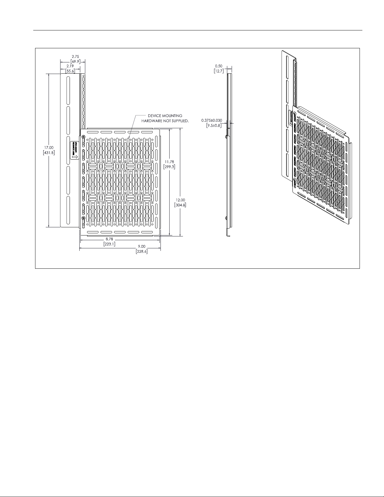
DIMENSIONS: INCHES
[MILLIMETERS]
DIMENSIONS
3
Page 4

CSMP9X12 Installation Instructions
Tighten Fastener
Apretar elemento de fijación
Befestigungsteil festziehen
Apertar fixador
Serrare il fissaggio
Bevestiging vastdraaien
Serrez les fixations
Loosen Fastener
Aflojar elemento de fijación
Befestigungsteil lösen
Desapertar fixador
Allentare il fissaggio
Bevestiging losdraaien
Desserrez les fixations
Phillips Screwdriver
Destornillador Phillips
Kreuzschlitzschraubendreher
Chave de fendas Phillips
Cacciavite a stella
Kruiskopschroevendraaier
Tournevis à pointe cruciforme
Open-Ended Wrench
Llave de boca
Gabelschlüssel
Chave de bocas
Chiave a punte aperte
Steeksleutel
Clé à fourche
By Hand
A mano
Von Hand
Com a mão
A mano
Met de hand
À la main
Hex-Head Wrench
Llave de cabeza hexagonal
Sechskantschlüssel
Chave de cabeça sextavada
Chiave esagonale
Zeskantsleutel
Clé à tête hexagonale
Pencil Mark
Marcar con lápiz
Stiftmarkierung
Marcar com lápis
Segno a matita
Potloodmerkteken
Marquage au crayon
Drill Hole
Perforar
Bohrloch
Fazer furo
Praticare un foro
Gat boren
Percez un trou
Adjust
Ajustar
Einstellen
Ajustar
Regolare
Afstellen
Ajuster
Remove
Quitar
Entfernen
Remover
Rimuovere
Verwijderen
Retirez
Optional
Opcional
Optional
Opcional
Opzionale
Optie
En option
Security Wrench
Llave de seguridad
Sicherheitsschlüssel
Chave de segurança
Chiave di sicurezza
Veiligheidssleutel
Clé de sécurité
LEGEND
4
Page 5

Installation Instructions CSMP9X12
#2
1/2"
Wire cutter
Mounting Plate Installation Hardware Kit
A (4)
[Thumb nut]
B (3)
10-32 x 3/8"
C (1)
5/16"
D (1)
[PEM Stud]
E (20)
F (2)
[Thumb screw]
G (1)
[Mounting plate]
H (1)
[Mounting bracket]
.625x.140x.031"
TOOLS REQUIRED FOR INSTALLATION
PARTS
5
Page 6

CSMP9X12 Installation Instructions
Mounting bracket
vertical and horizontal
installation examples
Mounting bracket (H)
(H)
Example display mount interface bracket
Back of
display
2
(H)
Display mount
interface
bracket
(D)
(C)
2
ASSEMBLY AND INSTALLATION
NOTE: The mounting bracket (H) may be installed using either of two methods. Proceed to either Installing Mounting Bracket to
VESA Holes OR Installing Mounting Bracket to Display Mount Interface Bracket.
Installing Mounting Bracket to VESA Holes
NOTE: The mounting bracket (H) may be installed using VESA holes between display mount interface brackets and the display in
vertical or horizontal positions. (See Figure 1)
1. Place display face down on a soft surface.
NOTE: Any existing display mount interface bracket hardware
that is already installed on the back of the display must
be removed before installing the mounting bracket (H).
2. Use the hardware provided with your display mount
interface brackets to attach mounting bracket (H) between
the display mount interface bracket and into the VESA holes
in the back of the display. (See Figure 2)
Figure 1
Installing Mounting Bracket to Display Mount
Interface Bracket
NOTE: Instead of attaching the mounting bracket (H) to VESA
holes in the back of the display, it may also be attached
directly to the display mount interface bracket.
1. Place display face down on a soft surface.
2. Connect the mounting bracket (H) to the desired point on
the display mount interface bracket with one PEM stud (D)
and flange nut (C). (See Figure 3)
Figure 2
Figure 3
6
Page 7

Installation Instructions CSMP9X12
(A) x 2
1
(F) x 2
(G)
Component
Component
fasteners
(E)
2
(G)
1
(B) x 2
(G)
(H)
Trim excess portion
of thumb screws
using a wire cutter
Installing Thumb Screws / Thumb Nuts
1. Attach two thumb screws (F) to two thumb nuts (A) through
corners of the mounting plate (G). (See Figure 4)
NOTE: The thumb screws and thumb nuts should be attached
to the corners on the side of the mounting plate (G)
opposite where the mounting bracket (H) will be
attached.
2. Using the fasteners provided with the component and the
washers (E), attach the component to the mounting plate
(G). (See Figure 5)
Attaching Mounting Plate to Mounting Bracket
1. Using two 10-32 x 3/8" thread forming screws (B) fasten
mounting bracket (H) to mounting plate (G). (See Figure 6)
Figure 4
Attaching Component
1. Place component(s) on mounting plate (G), and position in
the desired location with the hole pattern in mounting plate
best aligned to component mounting holes. (See Figure 5)
Figure 5
Figure 6
Adjusting / Trimming the Thumb Screws
1. Loosen the two thumb screws (F) from the two thumb nuts
(A) until the mounting plate (G) is parallel to the back of the
display. (See Figure 7)
2. Use a wire cutter to trim off remaining excess portion of the
two thumb screws (F). (See Figure 7)
Figure 7
7
Page 8

CSMP9X12 Installation Instructions
8800-003124 Rev01
2019 Legrand | AV
www.legrandav.com
03/19
USA/International A 6436 City West Parkway, Eden Prairie, MN 55344
P 800.582.6480 / 952.225.6000
F 877.894.6918 / 952.894.6918
Europe A Franklinstraat 14, 6003 DK Weert, Netherlands
P +31 (0) 495 580 852
F +31 (0) 495 580 845
Asia Pacific A Office No. 918 on 9/F, Shatin Galleria
18-24 Shan Mei Street
Fotan, Shatin, Hong Kong
P 852 2145 4099
F 852 2145 4477
 Loading...