

CHIEF CH1015T-NGE, CH1015T-NGEM, CH2025T-NGE, CH2025T-NGEM, CH1015T-LPGE Installation And Operation Manual
...Page 1
CENTRIFUGAL HEATER - CSA
INSTALLATION &
OPERATINGMANUAL
P/N 416274 Rev 0
NATURAL GAS
CH1015T-NGE/NGEM
CH2025T-NGE/NGEM
LIQUID PROPANE
CH1015T-LPGE / LPGEM
CH2025T-LPGE / LPGEM
VAPOR PROPANE
CH1015T-VPGE
CH2025T-VPGE
Page 2
WARNING: If the information in this manual is not followed exactly, a
fire or explosion may result causing property damage, personal
injury or loss of life.
- Do not store or use gasoline or other flammable vapors and
liquids in the vicinity of this or any other appliance.
- WHAT TO DO IF YOU SMELL GAS
o Do not try to light any appliance.
o Extinguish any open flames.
o Do not touch any electrical switch.
o Immediately call your gas supplier. Follow the gas
supplier’s instructions.
o If you cannot reach your gas supplier, call the fire
department.
- Installation and service must be performed by a qualified
installer, service agency or the gas supplier.
WARNING: Improper installation, adjustment, alteration, service or
maintenance can cause property damage, injury or death. Read the
installation, operating and maintenance instructions thoroughly
before installing or servicing this equipment.
FOR YOUR SAFETY
The use and storage of gasoline and other flammable vapors and
liquids in open containers in the vicinity of this appliance is
hazardous.
C H I E F I N D U S T RI E S, I N C. – AG RI / I N D U S TR I A L D I V I S I O N
Installation Manual
For more information about Chief Industries, Inc. and additional products or services please visit our website
Chief Industries, Inc. 800-359-7600 TOC – 416274 Page 2
Chief Industries, Inc.
4400 East 39th Street • PO Box 848
Kearney, NE 68847
Phone 800.359.7600
www.agri.chiefind.com
Page 3

Table of Contents
Introduction ........................................................................... 4
Model Number Description .............................................................. 4
Packing List ..................................................................................... 5
Before You Begin ................................................................. 6
Safety and Precautions ..................................................... 8
Heater and Control Enclosure Components ............. 11
Accessories: .................................................................................. 11
Explanation of Components: ......................................................... 12
Replacement Parts Common to All Models: .................................. 17
Replacement Parts for Specific Models: ....................................... 18
Heater Location and Foundation ................................................... 20
Gas Supply Installation ................................................................. 22
High Limit Installation .................................................................... 24
Fan Electrical Installation .............................................................. 25
Heater Electrical Installation .......................................................... 25
Installation of External Plenum Controls ....................................... 26
Operating Instructions ..................................................... 26
Heater Control: .............................................................................. 26
Start-Up Procedure: ...................................................................... 27
Drying Temperature Recommendations: ...................................... 28
Adjustments: ................................................................................. 30
Shut Down Procedures ................................................................. 31
Firing Rate Guideline Tables ......................................................... 32
Heater Maintenance ...................................................................... 37
Heater Wiring Diagram .................................................................. 38
Generic Sequential Operations Check: ......................................... 40
Condition Specific Faults: .............................................................. 41
STANDARD LIMITED WARRANTY......................................... 45
Chief Industries, Inc. 800-359-7600 TOC – 416274 Page 3
Page 4

C E N T R I F U G A L H E A T E R - C S A
Introduction
Thank you for purchasing a Caldwell Centrifugal Heater compliant to the Canadian Standards
Association performance guidelines. Proper installation will ensure you the best overall experience with
your heater and guarantee smooth operation. This manual is for the installation and operation of the
Caldwell Centrifugal Heater system that has been 100% factory quality control inspected, field simulated
and stress tested prior to shipment.
This proprietary information is loaned with the expressed agreement that the drawings and information
therein contained are the property of Chief Industries, Inc. and will not be reproduced, copied, or
otherwise disposed of, directly or indirectly, and will not be used in whole or in part to assist in making
or to furnish any information for the making of drawings, prints or other reproduction hereof, or for
the making of additional products or equipment except upon written permission of Chief Industries,
Inc. first obtained and specific as to each case. The acceptance of this material will be construed as an
acceptance of the foregoing agreement.
The technical data contained herein is the most recent available at the time of publication and is subject
to modification without notice. Chief Industries, Inc. reserves the right to modify the construction and
method of operation of their products at any time without any obligation on their part to modify any
equipment previously sold and delivered.
Model Number Description
The heater model nomenclature distinguishes the application of the heater. The information includes a
designation of the applicable fan and type of fuel to be utilized (natural gas, vapor propane, or liquid
propane). The model number is stamped on the serial number plate and the definition of the model
number nomenclature is as follows:
Example: CH 1015 - T - NGE
(a) (b) - (c) - (d)
(a) CH = Heater Unit (Canadian)
(b) 1015 = Fan Model Required by Horsepower
Where: 1015 = C27-10 or C27-15
Where: 2025 = C30-20 or C30-25
(c) T = Transformer and Flame Probe Ignition System
(d) NGE = Type of Fuel to be Utilized
Where
NGE = Natural Gas Fuel (Electric)
VPGE = Vapor Propane Gas Fuel (Electric)
LPGE = Liquid Propane Gas Fuel (Electric)
LPGEM = Liquid Propane Gas Fuel (Electric) with Modulating Valve
Chief Industries, Inc. 800-359-7600 INTRODUCTION -416274 Page 4
Page 5
C E N T R I F U G A L H E A T E R - C S A
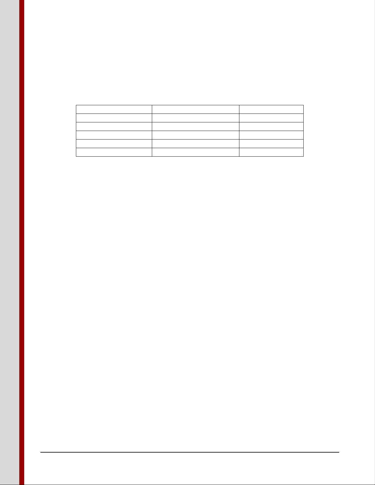
Quantity
Component
Description
1
Heater
Heater Assembly
1
Warranty Registration Card
Bulletin
1
Manual
Bulletin (464D)
1
Bolt Bag
Assembly
1
Orifice
Package
Packing List
The shipment should contain the following items. Verify and inspect all items carefully when unpacking
and before installing. In case of any shortage, contact your dealer. In case of damage during shipment,
file a claim with the carrier.
Note: Before starting the installation of the heater, verify that all items called out on the
packing list have been received.
Please note that this manual, part number 416274 includes and references Bulletin 464D. This manual
is for the installation, operation and maintenance of heater models with serial numbers 15F and above,
and is effective 5/1/2015.
Chief Industries, Inc. 800-359-7600 INTRODUCTION -416274 Page 5
Page 6
C E N T R I F U G A L H E A T E R - C S A
Date
Operator Signature
Owner Signature
Before You Begin
Read this manual thoroughly before operating this heater. Keep this manual in a
location for quick access and reference.
“The equipment shall be installed in accordance with the Natural Gas and Propane Installation Code,
CSA B149.1 and the Propane Storage and Handling Code, CSA B149.2, or applicable provincial
regulations, which should be carefully followed in all cases. Authorities having jurisdiction should be
consulted before installations are made.”
Your Caldwell heater is designed for safe and reliable operation when properly installed in combination
with a Caldwell fan. However the heater requires electricity and flammable gas, which when improperly
installed or when operated improperly, can be potentially dangerous. Anyone who will operate this unit
should read the manual before installing or operating this unit. The following table, provided for your
convenience, will aid in verifying that these individuals understand the proper operation of the heater.
After completely reading the manual, this table should be filled in.
Chief Industries, Inc. 800-359-7600 INTRODUCTION -416274 Page 6
Page 7
C E N T R I F U G A L H E A T E R - C S A
Special Service Note: If you are unable to remedy any service problem after thoroughly studying this
manual, contact the dealer from whom you purchased the unit. Your dealer is your first line of service.
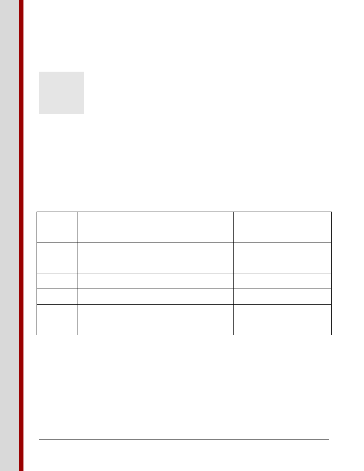
The following information is required for service:
1. Heater model number: __________________________________
2. Heater serial number: ___________________________________
3. Fan model number: ____________________________________
4. Fan serial number: _____________________________________
5. Type of fuel: _________________________________________
6. Type of external plenum control used: _____________________
7. Setting of the external plenum control: _____________________
8. Approximate operating pressure: __________________________
9. Hours the unit has been in operation: ______________________
10. Diameter and eave height of bin: _________________________
11. Grain depth: _________________________________________
12. Type of grain stored: ___________________________________
13. Moisture content of the grain: ____________________________
14. Dealer purchased from: _________________________________
15. Dealer address and phone number: ________________________
16. Date purchased: _______________________________________
17. Service contractor:
a. Name: _____________________________________________
b. Address: ____________________________________________
c. Phone: _____________________________________________
Chief Industries, Inc. 800-359-7600 INTRODUCTION -416274 Page 7
Page 8

C E N T R I F U G A L H E A T E R - C S A
Safety and Precautions
Your safety and the safety of others is a primary concern to Chief Industries, Inc. This manual was
written to assist in the safe installation and operation of the Caldwell Heater.
It is your responsibility as the owner, builder, operator, or supervisor to know what specific
requirements, precautions and hazards exist and to make these known to all personnel working with
equipment or on the jobsite so that they can observe any necessary safety precautions.
All personnel, including the installation crew, must read and understand the information contained in
this manual before starting construction. Chief Industries, Inc. is not responsible or liable for the
misuse of equipment or operation of personnel or equipment in an unsafe manner.
Chief Industries, Inc. assumes no liability with respect to proper construction and inspection, assembly,
or use of its products established under applicable laws, all of which is the sole responsibility of the
purchaser and those authorized for the installation.
Follow all local and federal safety laws and regulations. Verify that all equipment and personnel
conform to any applicable jurisdiction regulations.
Work Area Safety Statement
To ensure the safety of all individuals in the work area, only authorized and trained persons shall install,
maintain and use the Caldwell Heater.
Under no circumstances should unauthorized individuals be allowed to trespass or be present in the
work area.
It shall be the duty of all operators to ensure that the work area is clean, organized and kept free of all
debris and tools that might cause an accidental tripping or falling hazard.
Special care should be taken when working from unsafe heights. Common sense dictates that when
conditions such as rain or wind prohibit the safe use of equipment, the installation be discontinued.
Chief Industries, Inc. strongly recommends that equipment meeting the current specifications be used,
whether the individual operator is required by law to do so or not. Proper climbing equipment and a
secured safety harness should be used at all times when performing operations work, installation or
maintenance.
Field modifications without the authorization of the manufacturer may present unknown dangers to the
operator and must be avoided.
Auxiliary Equipment Safety
You may decide to purchase and install “auxiliary equipment” made by other manufacturers. Chief
Industries, Inc. has no control over the design and manufacture of this equipment. In view of this, at a
minimum, we suggest you do the following:
Chief Industries, Inc. 800-359-7600 SAFETY - 416274 Page 8
Page 9

C E N T R I F U G A L H E A T E R - C S A
1. Obtain, read and understand the instructions and safety cautions of the auxiliary equipment
manufacturer. Be certain that all equipment is installed in agreement with those instructions.
2. Check with Chief Industries, Inc. to verify that your system is designed to support any additional
loads supplied by the auxiliary equipment.
3. Obtain any applicable safety decals from the manufacturer and make certain they are displayed
in a visible location.
4. Make certain that all electrical equipment is properly installed and grounded by a qualified
electrician.
5. Check availability and operation of electrical lock out and emergency stop systems.
6. Be certain that all guards and shields are securely in place.
7. Store all operation / maintenance manuals in a safe place for future use.
Heater Safety
Before operating the unit, perform the following checks:
1. Verify the fan, heater and transition units are bolted securely together. Verify the screen guard is
secured in place.
2. Verify the units are wired in compliance with the national electrical code, and the ground wire is of
sufficient size to provide lightening protection.
3. Verify the gas supply is installed correctly according to instructions.
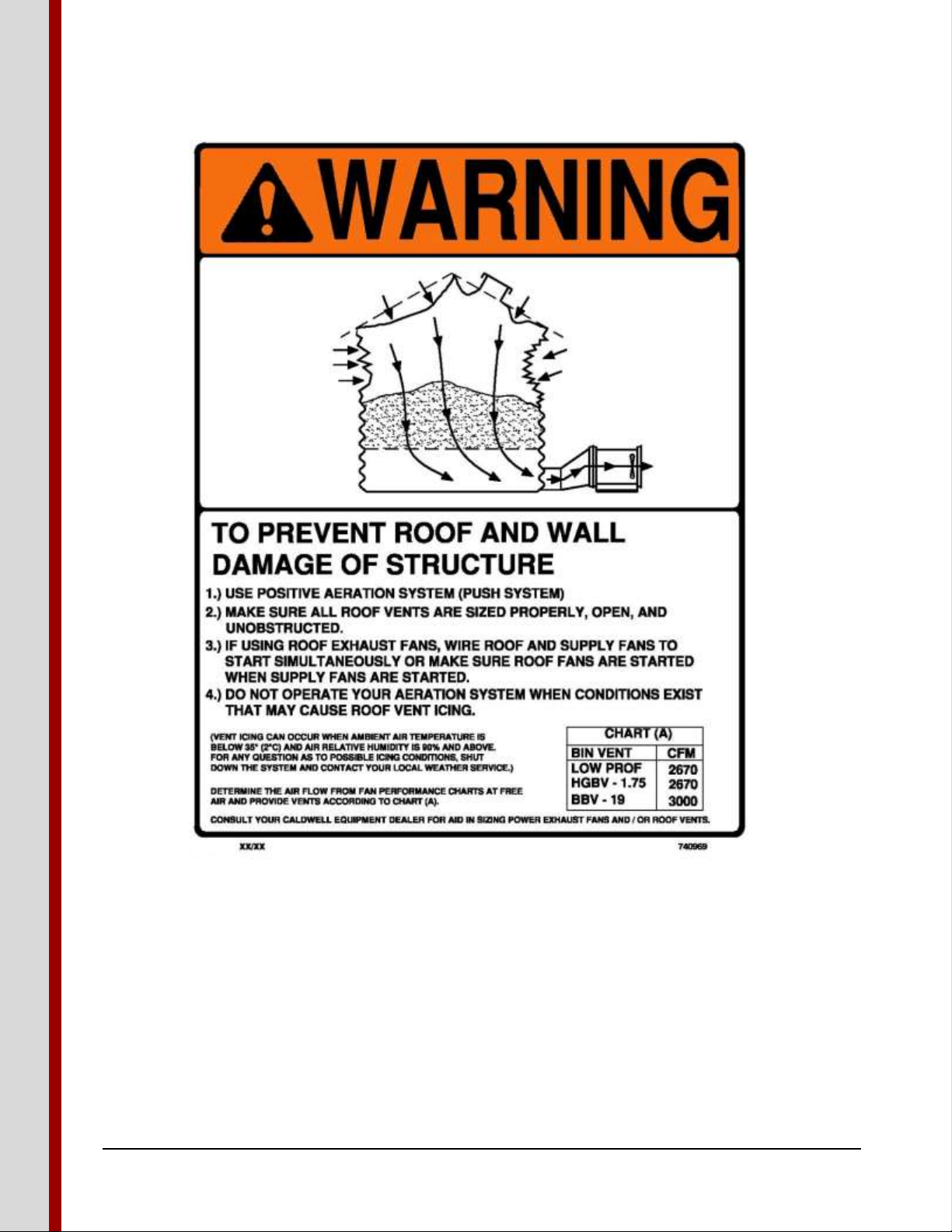
4. Provide sufficient bin exhaust vents or fans, and verify that they are open and operational before
starting the drying system. These vents or fans are necessary to provide an exhaust path for moisture
laden air (reducing condensation), and also to prevent pressurization of the bin above the grain mass
and causing damaging loads on the bin and roof structure. Do not operate units when conditions are
such that freezing of the vents could occur.
a. Heed the following warning:
Chief Industries, Inc. 800-359-7600 SAFETY - 416274 Page 9
Page 10
C E N T R I F U G A L H E A T E R - C S A
Chief Industries, Inc. 800-359-7600 SAFETY - 416274 Page 10
Page 11

C E N T R I F U G A L H E A T E R - C S A
Heater and Control Enclosure Components
The following outlines the accessories, general components and replacement part numbers for the
Caldwell heater models.
Accessories:
1. A humidistat, thermostat, or thermostat-humidistat control is not included with the standard heater.
These controls are to be ordered separately. A dual humidistat-thermostat kit can be ordered so that
one control assembly can be used when two heater units are used on the same bin.
2. Caldwell requires using a fuel line strainer in the fuel line just before the fuel enters the heater
plumbing. A line strainer is provided on all units. A line strainer can be obtained from Caldwell, or
your gas company. Caution: Your warranty could be jeopardized if the heater should malfunction
due to foreign material in the heater plumbing lines if the fuel supply line is not fitted with a line
strainer.
3. When wiring a heater to a 460 or 575 volt fan, a step down transformer must be used to develop 115
volt, single phase, 60 cycle power (part #9717033).
Chief Industries, Inc. 800-359-7600 COMPONENTS - 416274 Page 11
Page 12
C E N T R I F U G A L H E A T E R - C S A
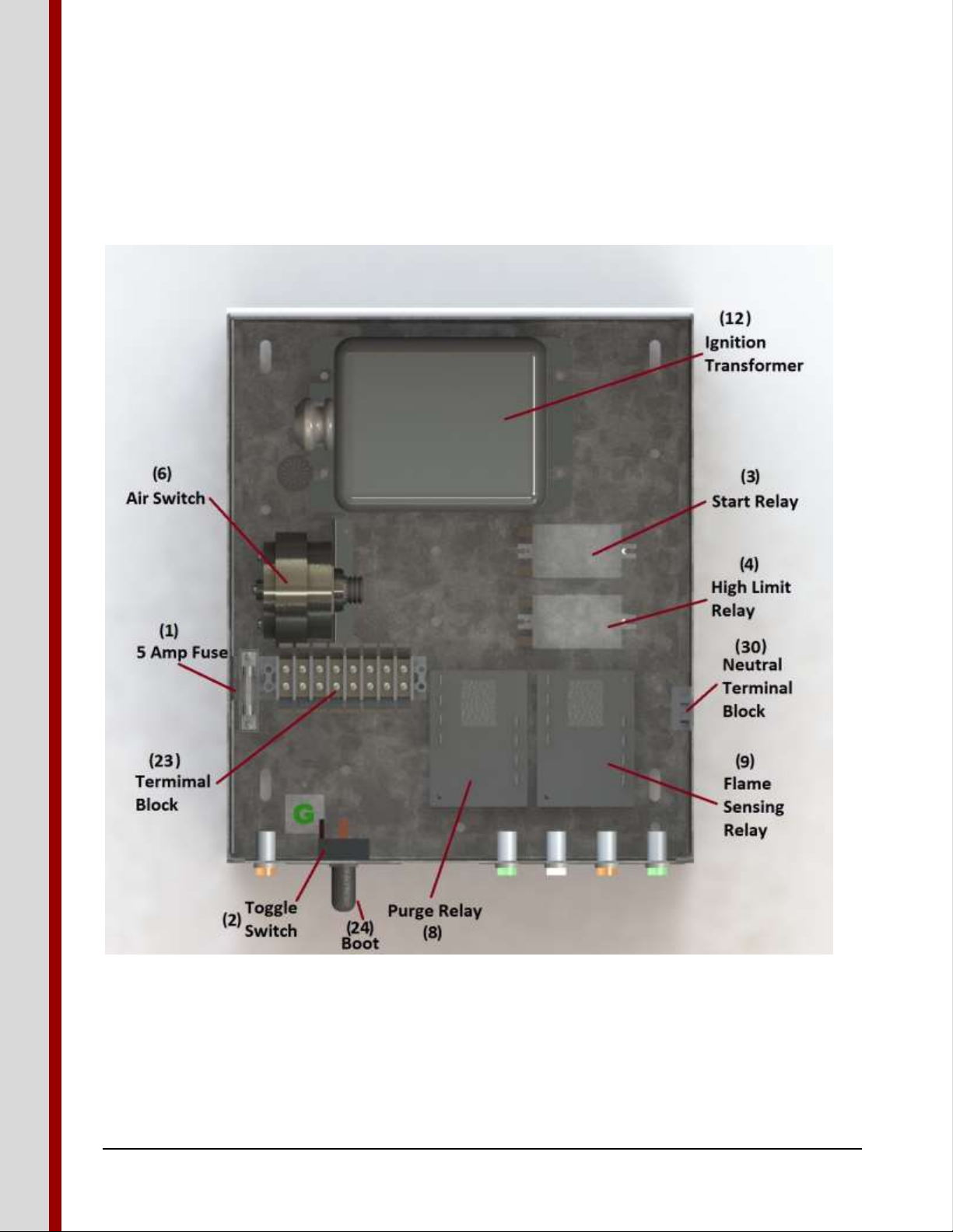
Explanation of Components:
Please note the location and general description of the primary components and their function.
Control Enclosure Components:
Chief Industries, Inc. 800-359-7600 COMPONENTS - 416274 Page 12
Page 13
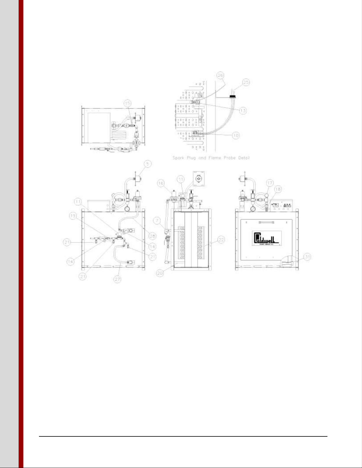
Heater Body Components:
C E N T R I F U G A L H E A T E R - C S A
The balloon callouts shown in the above illustration specify each component of the heater.
1. 5 Amp Fuse (#850412) - The fuse protects the heater control circuit from excessive current draw.
2. Toggle Switch (#710707) - The toggle switch is the heater "On" and "Off" and “Momentary Start”
switch.
3. Start Relay (#756692) – A start relay is utilized to prove that the flame probe is functioning properly
with every trial for ignition. If the flame probe is functioning properly the relay allows the purge to
energize. If the flame probe is not functioning properly the start relay prevents the initiation of the
ignition process.
4. High Limit Relay (#756692) – The high limit relay is activated by the high limit. The slave relay
shuts off the spark and fuel to the burner and maintains the off condition until the operator
Chief Industries, Inc. 800-359-7600 COMPONENTS - 416274 Page 13
Page 14

C E N T R I F U G A L H E A T E R - C S A
determines the reason for the high limit activation. The slave relay is reset by turning the heater
toggle switch to the off position.
5. High Limit (#776443) - The high limit control, located in the bin plenum, is a manual resetting
temperature limiting control, used to protect the heater, not the bin plenum, from excessive heat.
The high limit control activates the slave relay to shut off the heater if the plenum temperature
reaches 230° F (110° C). Note: The high limit is not an operating control; the operator must utilize
an operating control to set the firing rate for the desired drying plenum temperature.
6. Air Switch (#785691) - The air switch is a control that senses the flow of air from the fan to the
heater. If, for any reason, the air flow is stopped, the air switch will shut off the heater. The air
switch will keep the heater shut off until air flow from the fan is re-established. If the air switch cycles
off from a lack of air, turn the heater toggle switch off before restarting the fan.
7. Vapor Temperature Limit (#157200) - The vapor temperature limit is an automatic resetting
temperature limiting control used to protect the solenoid valve and regulator from being damaged
due to excessive gas temperature coming from the vaporizer. Also, the vapor temperature limit
protects the vaporizer from re-cracking the propane and causing an oil film to deposit on the burner.
The vapor temperature limit is set to shut off the heater if the gas from the vaporizer reaches a
temperature of 160°F (71°C). The control will allow the heater to reignite after the vaporizer cools.
The vapor temperature limit is only on LPGE heaters.
8. Purge Delay with 30 sec Time Delay (#719914) - Purge delay is a time delay relay used to delay the
energizing of the ignition transformer and solenoid valves for 30 seconds after the heater is turned on
to allow for the removal of any raw gas from the heater before ignition is tried. The purge delay calls
for a 30-second delay before ignition, regardless which control is sued to turn the heater on.
9. Flame Sensing Relay with 30 sec Time Delay (#719914) - The flame sensing relay has a 30
second delay and is used to break the circuit to the solenoid valves and ignition transformer if the
flame probe does not establish the presence of the flame at the burner. The operator will have to
manually reset the flame sensing relay by moving the power switch to off, before retrying for ignition.
10. Flame Probe (#749812) - The flame probe is a switch that is sensitive to heat, and is used to
establish the presence or absence of flame at the burner. The flame probe is used with the flame
sensing relay, as the flame safeguard circuit of the heater. The switch is opened on temperature rise.
11. Solenoid Valves - Solenoid valves are shut-off valves that are electrically operated. The valves are
opened automatically when energized, and are closed automatically when de-energized.
12. Ignition Transformer (#851790) - The ignition transformer is a transformer used to create the
6,000 secondary volts necessary for spark at the spark plug.
13. Spark Plug (#851402) - The spark plug is used to ignite the fuel at the burner. The spark plug will
spark while the ignition transformer is energized.
Chief Industries, Inc. 800-359-7600 COMPONENTS - 416274 Page 14
Page 15

C E N T R I F U G A L H E A T E R - C S A
14. Fuel Line Strainer - The fuel line strainer is used to remove foreign particles from the fuel before
the fuel enters the heater plumbing. If these particles are not removed, possible operating difficulties
could occur.
15. Vapor Valve - The vapor valve is used for preliminary adjustment of the firing rate by opening and
closing the valve to generate the proper plenum temperature. Once the proper firing rate is
established, the regulator needs to be adjusted to the firing rate that is required.
16. Regulator - The regulator is used to regulate the firing rate of the heater. The regulator is not used to
regulate the fuel from the fuel sources. A separate regulator should be used for regulating the fuel at
the fuel source.
17. Pressure Gauge - The pressure gauge is used to indicate the amount of fuel pressure at the orifice.
The pressure is used as a tool to set the firing rate.
18. Orifice - The orifice is an opening at the end of the heater plumbing that develops a restriction to gas
flow, which allows the pressure gauge to develop a pressure reading, so that the firing rate of the
heater can be field set.
19. Liquid Shut-Off Valve (#714949) - The liquid shut off valve is used as a manual shut off valve and
is used to stop fuel from entering the heater. The liquid shut off valve has only two positions: open
or closed. The liquid shut off valve is only on LPGE heaters.
20. Vaporizer (#9752584) - The vaporizer is used on LPGE heaters only, and is used to convert the
liquid propane gas to propane vapor gas by using the heat supplied by the burner.
21. Hydrostatic Pressure Relief Valve (#716878) - The hydrostatic pressure relief valve is used to
protect the heater plumbing components from excessive fuel pressure by relieving the excessive fuel
pressure from gas trapped between shut off valves to the atmosphere. If a hydrostatic pressure relief
valve opens, replace the relief valve.
22. Burner - The burner is a component in the heater where the fuel and air are mixed and then burned.
23. Terminal Block 8 POLE (#749614) - The terminal block is used as a junction block for connecting
the lead wires of the various electrical parts.
24. Toggle Switch Protective Boot (#712034) - The toggle switch boot is used to eliminate water
entering the heater controls through the toggle switch.
25. Flame Probe Wire - The flame probe wire is used to connect the flame probe to the control box.
26. Spark Plug Wire - The spark plug wire is used to connect the spark plug to the ignition transformer.
27. Liquid Propane Hose (#715276) - The liquid propane hose is used to connect the liquid plumbing
line to the inlet of the vaporizer.
28. Vapor Propane Hose (#155820) - The vapor propane hose is used to connect the vaporizer to the
vapor propane line.
Chief Industries, Inc. 800-359-7600 COMPONENTS - 416274 Page 15
Page 16

C E N T R I F U G A L H E A T E R - C S A
29. Burner High Limit Wire (#9701961) - Wiring that connects the burner high limit and burner
exhaust limit to the control box.
30. Neutral Terminal Block 3 POLE (#850255) - This terminal block is used as a junction block to
establish a common neutral for connection of the neutral leads.
31. Venturi Weldment (#9415661) - The venturi weldment creates a high and low pressure area in the
airflow, which aids the air switch in measuring air velocity.
32. Humidistat Control (#9850982) - The humidistat control is an electrical operating control that is
wired into the heater to cycle the heater "On" and "Off" with respect to the relative humidity of the
drying air. The humidistat control is typically set at about 50% - 60% relative humidity of the drying
air. When the relative humidity is higher than the humidistat setting, the heater is cycled "On" and is
left on until the relative humidity is below the humidistat setting. If the relative humidity of the drying
air is less than the humidistat setting, the heater is cycled "Off" until such time that the relative
humidity would become greater than the setting of the humidistat. The humidistat control is for low
temperature drying.
33. Thermostat Control (#9851014) - The thermostat control is an electrical operating control that is
wired into the heater to cycle the heater "On" and "Off" with respect to the temperature of the drying
air. The thermostat is set at a desired temperature, and if the drying air temperature is higher than the
thermostat setting, the heater is cycled "Off." If the drying air temperature is less than the thermostat
setting, the heater is cycled "On," and is left on until such time that the drying air temperature is
above the thermostat setting.
34. Humidistat-Thermostat Control (#9870974) - The humidistat-thermostat control is an electrical
operating control that is wired into the heater to cycle the heater "On" and "Off" with respect to both
the drying air relative humidity and temperature. The humidistat-thermostat control will cycle the
heater on if either the drying air relative humidity is too high, or the drying air temperature is too low
with respect to the humidity setting or temperature setting of the control. NOTE: The optional
external plenum controls do not function in the same manner as a thermostat in a residential house.
When the bin plenum controls reach the set point the heater is then shut off. In the off mode the
bin’s plenum temperature will drop below the set point of the control due to the rapid air change in
the plenum from the fan. The controls do not sense the instantaneous change in air temperature but
take time to reach the plenum control setting before controlling the heater operation. NOTE: The
firing rate must be set by the operator to verify excessive temperature is not present in the plenum.
35. Modulating Valve - The modulating valve is a non-electrical operating control. The modulating
valve is placed in the heater plumbing, and controls the amount of fuel burned by the heater
depending upon the temperature of the drying air. If the temperature of the drying air is lower than
the temperature setting of the modulating valve, the modulating valve opens up and more fuel is
burned to raise the drying air temperature. If the drying air temperature is higher than the
temperature setting, the modulating valve restricts the amount of fuel to the heater. The modulating
valve has an interchangeable by-pass orifice to maintain continuous low heat operation regardless of
modulating valve setting. The orifice is interchangeable for establishing lower or higher by-pass flow
through the modulating valve, depending on conditions.
Chief Industries, Inc. 800-359-7600 COMPONENTS - 416274 Page 16
Page 17

Replacement Parts Common to All Models:
ITEM #
PART DESCRIPTION
PART NUMBER
1
5 Amp Fuse
850412
2
Toggle Switch
710707
3
Slave Relay
756692
4
High Limit
776443
5
Air Switch
785691
6
Vapor Temperature Limit (LPGE units only)
157200
7
Purge Relay (30 sec. time delay)
719914
8
Flame Sensing Relay (30 sec. time delay)
719914
9
Flame Probe
749812
11
Ignition Transformer
851790
12
Spark Plug
851402
16
Pressure Gage LP
851543
16
Pressure Gage NG
715011
22
Terminal Block (8 POLE)
749614
23
Toggle Switch Boot
712034
26
Liquid Propane Hose
715276
27
Vapor Propane Hose
155820
29
Neutral Terminal Block (3 POLE)
850255
31
Venturi
9415661
32
Nylon Humidistat Control (Not Shown)
9850982
33
Thermostat Control (Not Shown)
9851014
34
Humidistat-Thermostat Control (Not Shown)
9850974
35
Modulating Valve Kit (Propane) (Not Shown)
9701862
35
Modulating Valve Kit (Nat. Gas) (Not Shown)
9767954
C E N T R I F U G A L H E A T E R - C S A
Chief Industries, Inc. 800-359-7600 COMPONENTS - 416274 Page 17
Page 18

Replacement Parts for Specific Models:
CH1015TNGE
CH1015TVPGE
CH1015TLPGE
CH1015TLPGEM
ITEM #
PART DESCRIPTION
PART #
PART #
PART #
PART #
10
Vapor Solenoid Valve
789263
789255
789255
189255
10
Liquid Solenoid Valve
753863
753863
13
Vapor Fuel Line Strainer
851626
851626
851626
851626
13
Liquid Fuel Line Strainer
851634
851634
14
Vapor Valve
714931
714931
714931
714923
15
Regulator
753905
715003
715003
715003
17
Orifice
9720516
9422253
9422253
9422253
18
Liquid Valve
714949
914949
19
Vaporizer
9752584
9752584
20
Hydrostatic Pressure Relief Valve
716878
716878
21
Burner
9784793
9784793
9784793
9784793
24
Flame Probe Wire
9730515
9730515
9730515
9730515
25
Spark Plug Wire
9701995
9701995
9701995
9701995
CH2025TNGE
CH2025TVPGE
CH2025TLPGE
CH2025TLPGEM
ITEM #
PART DESCRIPTION
PART #
PART #
PART #
PART #
10
Vapor Solenoid Valve
789263
789263
789263
789263
10
Liquid Solenoid Valve
753863
753863
13
Vapor Fuel Line Strainer
851626
851626
851626
851626
13
Liquid Fuel Line Strainer
851634
851634
14
Vapor Valve
714931
714931
714931
714931
15
Regulator
775502
715003
715003
715003
17
Orifice
9719328
9714881
9714881
9714881
18
Liquid Valve
714949
914949
19
Vaporizer
9752584
9752584
20
Hydrostatic Pressure Relief Valve
716878
716878
21
Burner
9787840
9787840
9787840
9787840
24
Flame Probe Wire
9730531
9730531
9730531
9730531
25
Spark Plug Wire
9701995
9701995
9701995
9701995
C E N T R I F U G A L H E A T E R - C S A
Chief Industries, Inc. 800-359-7600 COMPONENTS - 416274 Page 18
Page 19

C E N T R I F U G A L H E A T E R - C S A
Installation Requirements
The following illustration describes the components necessary for a typical installation. The drying unit
(fan, heater, and transition) should be located such that the heated air can enter the bin plenum chamber
uniformly. Verify all the components needed for the drying system are present. The fan and heater
should be located opposite the unloading tube for best air distribution.
Chief Industries, Inc. 800-359-7600 INSTALLATION - 416274 Page 19
Page 20

C E N T R I F U G A L H E A T E R - C S A
Heater Location and Foundation
The following illustration shows a typical installation of 2 drying units and optional plenum controls. If
two drying units are used on the same bin, locate them 4’ (1.21m) to within 45° of each other and
centered opposite the unloading tube. Locate any humidistat or thermostat control between the two
heater units, making sure control senses heat from both units (order kit #9735035).
Chief Industries, Inc. 800-359-7600 INSTALLATION - 416274 Page 20
Page 21

C E N T R I F U G A L H E A T E R - C S A
For proper operation of heater, the fan and heater are to be mounted on a level pad. The pad should be
the same height as the concrete floor. The size of the pad should be as indicated in the following
illustration.
Chief Industries, Inc. 800-359-7600 INSTALLATION - 416274 Page 21
Page 22

C E N T R I F U G A L H E A T E R - C S A
Before installing heater please verify the following:
1. That the spark plug is gapped at 1/8" (.32cm). If not, gap to 1/8" (.32cm).
2. That the flame probe and spark plug wires are attached.
3. That all bolts, including carriage bolts and screws are tight.
4. The heater is installed on the air discharge end of the fan. Check air flow decals on the fan and heater
to verify heater is oriented properly. Connect the heater to the transition with bolts provided in the
fan bolt bag. The installation should appear as illustrated previously.
Gas Supply Installation
Refer to the dryer rating plate to locate the minimum gas supply pressure for obtaining the maximum
gas capacity for which this dryer is specified.
The gas piping installer is to locate a manual emergency shutoff valve in an appropriate location that
allows access to this valve in case of a fire, explosion or other emergency at the heater.
Propane Gas
Chief Industries, Inc. 800-359-7600 INSTALLATION - 416274 Page 22
Page 23

C E N T R I F U G A L H E A T E R - C S A
For a typical propane tank installation a 1000 gallon tank is recommended as the minimum size to avoid
frequent refilling. (Raising the air temperature 100°F (38°C) on an airflow rate of 10,000 CFM
(283m³/min) would require approximately 300 gallons of liquid propane per day.) Also the larger tank
will aid in the vaporization of the liquid propane.
Note: Never use an anhydrous ammonia tank as your LP gas tank. Contaminants in the tank can be harmful
to the heater, and safety devices may not meet liquid propane storage codes.
The supply tank should be placed at least 10’ (3.05m) from the heater. Because some areas may require
a greater distance, please consult your local authorities.
The supply tank should be equipped with a liquid valve and vapor valve. The inlet of the liquid valve
should be located 12” (31cm) from the tank bottom to avoid impurities getting into the gas line and
heater.
The liquid valve and vapor valve on the propane tank should be connected as illustrated. This allows
the operator to run the LPGE and LPGEM units on vapor or liquid propane.
A minimum 60 psig (414kPa) pressure regulator is recommended, located as shown. The regulator
provides uniform flow, and reduces the pressure on the gas line from the regulator to the heater for
added safety. The regulator is required on vapor and liquid propane installations. Verify that the supply
tank has a relief valve present and that it is properly sized and located.
Chief Industries, Inc. 800-359-7600 INSTALLATION - 416274 Page 23
Page 24

C E N T R I F U G A L H E A T E R - C S A
Natural Gas
The natural gas service should be able to provide a minimum of 5 psig (34kPa) when the heater is
operating. Check with your gas supplier to verify that the supply pressure has the pressure potential to
deliver natural gas for the length of the service line.
A line strainer must be located at the heater (order part #714709).
The natural gas service should be regulated. Contact your gas supplier. A regulator can be obtained
from Caldwell (order part #753905).
Fuel Line Installation
The suggested tubing size to be used from the supply to the heater is 5/8" (1.59cm) O.D. type K
copper tubing or 1/2" (1.27cm) black schedule 80 steel pipe. If copper tubing is used, make a loop in
the tubing within 3’ (0.9m) of the heater to absorb shock. If 1/2" (1.27cm) steel pipe is used, run the
plumbing to within about 3’ (0.9m) of the heater, and use three feet of 3/8" (.95cm) minimum I.D. high
pressure flexible hose, (CGA approved for propane). Be careful not to turn or twist the heater
plumbing parts because the proper operation of these can be affected or leaks in joints can be
developed. Verify all foreign material is out of the gas line before connecting the line to the heater.
If your natural gas supply pressure is not adequate to maintain 10 psig (69kPa) at the heater, use a one
inch or larger service line and verify that 5 psig (34kPa) natural gas pressure is available when the heater
is operating. Install a line strainer between the natural gas heater and the service line.
Check all connections for leaks with a soap test. Open the supply valve at the source and use a liquid
detergent and brush all fittings and joints. If bubbles are generated at the fitting, gas is escaping from
the joint. With the installation of the service line, inspect all parts that are added, and the heater
plumbing parts affected by the installation. Tighten the components that are not sealing and replace if
cracked or defective.
Note: Do not use galvanized pipe fittings.
High Limit Installation
The High Limit control is connected by conduit to the control enclosure of the heater. The High Limit
will need to be installed into the bin plenum as shown in the following illustration. Install the high limit
on the right hand side of the transition, 2’ - 3’ (.60m - .91m) from the transition, approximately midway
up in plenum space under the drying floor. Drill a 4.0" (10.16cm) diameter hole centered on a valley of
the bin corrugation. Next place the limit control in the 4.0" (10.16cm) hole and match drill (4) 7/32"
(.55cm) diameter mounting holes located on the corrugation hill. Field seal around the high limit and
fasten using (4) 1/4" (.64cm) sheet metal screws located in the bolt bag to secure the High Limit to the
bin wall.
Chief Industries, Inc. 800-359-7600 INSTALLATION - 416274 Page 24
Page 25

Fan Electrical Installation
C E N T R I F U G A L H E A T E R - C S A
Connect the fan unit to the electric power source following the recommended wiring procedure
indicated in the fan manual. The electrical disconnect switch for the fan shall be sized with adequate
ampacity for the fan rating and installed in accordance with the Canadian Electrical Code Part 1 (CSA
Standard C22.1) and any local requirements.
Heater Electrical Installation
Note: The heater is electrically interlocked with the fan electrical service.
The heater operates on 115 volt, single phase, 60 cycle power. For fans wired for 230 volt, verify that
the fan is wired with a neutral wire to the middle terminal of the fan terminal block (#2), as well as a
ground wire linked to the bottom terminal of the fan terminal block (#3) as shown. The heater power
cord is wired into the fan controls by connecting the black wire to the terminal (#1), the white wire to
terminal (#2), and the green wire to terminal (#3) of the fan terminal block, as shown. With the heater
wired into the fan circuitry, the fan must be operating before power is available to the heater.
Chief Industries, Inc. 800-359-7600 INSTALLATION - 416274 Page 25
Page 26

C E N T R I F U G A L H E A T E R - C S A
For fans wired for 460 or 575 volt, three phase power and 230 volt, three phase power, a step down
transformer must be used to convert the 460 or 575 volt system and 230 volt system to 115 volt, single
phase, 60 cycle power for the heater.
When installing a thermostat, humidistat, or thermostat-humidistat control, the control power cord is
wired into terminals #6 and #7 of the heater terminal block. Remove the jumper wire linking terminals
#6 and #7, and connect one lead of the control power cord to terminal #6 and the other lead to
terminal #7. The control leads can be interchanged.
Installation of External Plenum Controls
For the proper installation of a thermostat, humidistat, or thermostat-humidistat control to the bin, the
installation of a dual humidistat-thermostat kit, or the installation of a vaporizer or a modulating valve
to the heater, refer to the installation instruction provided with each accessory.
Operating Instructions
Heater Control:
Information on the operating characteristics of the Centrifugal heater with a flame sensing system is
outlined in the following illustration. The flame sensing relay is reset by de-energizing the heater circuit
after a loss of flame condition.
Chief Industries, Inc. 800-359-7600 INSTALLATION - 416274 Page 26
Page 27

C E N T R I F U G A L H E A T E R - C S A
The operating characteristics of the flame sensing circuit are outlined as follows:
1. The flame probe is checked for proper functionality every time the heater is started. The heater
toggle switch is pushed to the “START” position. If the flame probe is in good condition, the purge
light is illuminated. If the flame probe is not good, the flame probe will require replacement.
2. Once the flame probe is checked, the remaining internal and external heater sensors have power
available. If all sensors call for heater operation, after a 30 second time frame to complete the purge
cycle, the transformers and solenoids are energized, and the ignition light is illuminated.
3. If no flame is at the burner or the flame probe is not positioned to monitor the flame, the flame
sensing relay will de-energize the solenoids and transformer after approximately 30 seconds. The
flame lock-out light will be illuminated. The condition that resulted in the loss of flame at the flame
probe needs to be addressed. The flame sensing relay is reset by switching the heater power switch to
“OFF”.
4. The heater then can be restarted by repeating the operation steps.
Start-Up Procedure:
Note: The heater is designed to operate at various firing rates. The operator must adjust
the firing rate for correct operation based upon the conditions present.
Chief Industries, Inc. 800-359-7600 OPERATION - 416274 Page 27
Page 28

C E N T R I F U G A L H E A T E R - C S A
Refer to the dryer rating plate to locate the minimum gas supply pressure for obtaining the
maximum gas capacity for which this dryer is specified.
1. Verify all roof vents are open and unobstructed. Note: if freezing of roof vents could occur,
do not operate the system.
2. Verify all controls are installed correctly. Refer to the ratings plate for determining the
minimum gas supply pressure to achieve the maximum gas capacity for which the heater is
specified.
3. Turn fan on by placing fan switch in an "On" position.
4. Open supply valve at the regulator.
a. It is preferable to start liquid propane units on vapor fuel. (After warm up, open liquid
valve on the supply tank approximately 1 turn, and close vapor valve.)
5. Open liquid valve (on LPGE Heaters only).
6. Open vapor valve.
7. Turn heater on by placing toggle switch to “Momentary Start” then "On" position.
8. Open regulator at heater slowly to 2 psig (14kPa) fuel pressure for low temperature start.
9. Set plenum external controls for desired heater operation. (See adjustment section of this
manual for more information.)
10. Wait at least 40 seconds for ignition to occur. The heater has a 30-second pre-purge before
ignition.
11. Perform a gas leak check during start up to verify the gas tightness of the gas train components
and piping under normal operating conditions.
12. If burner fails to ignite in 40 seconds, close regulator and vapor valve and turn off the heater by
placing toggle switch to the "Off" position. (Refer to service section of this manual for trouble
shooting of heater.)
13. If the high limit shuts the burner off, the high limit indicator light will be illuminated. Once the
high limit has cooled to a lower temperature, the high limit is reset by turning the heater switch
off and then back on. The repeated shutting off of the burner by the burner high limit is caused
by excessive static pressure, lack of air flow or a firing rate set too high. Reduce the static
pressure or air blockage before re-firing unit. If needed adjust the firing rate.
Drying Temperature Recommendations:
To determine the appropriate drying temperature, the crop to be dried and the drying system used must
be established. When this information is known, refer to the following table for the recommended
maximum plenum temperatures.
In using the recommended drying temperatures please be aware of the following information:
1. The rate of drying is increased with increased temperature, however susceptibility to grain
damage also increases.
Chief Industries, Inc. 800-359-7600 OPERATION - 416274 Page 28
Page 29

C E N T R I F U G A L H E A T E R - C S A
Recommended Drying Temperatures of Non-Seed Crops
Crop
In Bin Continuous Drying
Stir Drying
In Bin Batch Drying
Corn
160°F (71°C)
140°F (60°C)
120°F (49°C)
Grain Sorghum
160°F (71°C)
140°F (60°C)
120°F (49°C)
Wheat
140°F (60°C)
120°F (49°C)
110°F (43°C)
Rice
105°F (40°C)
100°F (38°C)
90°F (32°C)
Oats
140°F (60°C)
120°F (49°C)
110°F (43°C)
Sunflowers
110°F (43°C)
110°F (43°C)
100°F (38°C)
Soybeans
120°F (49°C)
120°F (49°C)
110°F (43°C)
Pinto Beans
100°F (38°C)
100°F (38°C)
100°F (38°C)
2. Wet grain will remain relatively cool due to moisture evaporation from the kernel, however dry
grain will warm to the drying temperature.
3. The drying front moves from the base of the bin upward. When operated as a batch system and
when a stirring machine does not reach the floor, significant over drying can occur at the base of
the bin.
4. When drying grain and focusing on kernel quality, use as low a plenum temperature as possible.
Note: Do not automatically set the plenum temperature at the maximum
recommendation.
5. When the grain is nearly dry, reduce the plenum temperature to complete the drying. This will
reduce the quantity of cracked grain generated and reduce the fire hazard.
6. When drying sunflowers, exercise caution because sunflowers are very flammable. Do not
exceed the temperature recommendations. Also, be aware that the chaff from sunflowers is
very flammable. Good housekeeping in the plenum chamber and around the bin is essential.
- Note: Temperature recommendations are based on non-seed crops (to be marketed
commercially). For seed crops, do not exceed 110°F (43°C), except for pinto beans
do not exceed 100°F (38°C).
- For other crops contact your extension service or Chief for drying temperature
recommendations.
Chief Industries, Inc. 800-359-7600 OPERATION - 416274 Page 29
Page 30

C E N T R I F U G A L H E A T E R - C S A
Adjustments:
The following adjustments will have to be made, depending upon the kind of heater and plenum
external controls being used. These adjustments cannot be made at the factory due to the differences in
bin setups, drying methods, and weather climates. These adjustments should be checked at least twice a
day or every 6 hours of operation to verify that the heater is functioning properly, and that the desired
results are being achieved. In using the recommended drying temperatures keep the following
considerations in mind:
Vaporizer Adjustment
The vaporizer is used on LPGE units and is located in the flame established by the burner. The
vaporizer uses heat from the burner to convert the liquid propane at the vaporizer entrance to vapor
propane. The burner requires vapor propane for proper operation.
The vaporizer outlet is connected to the vapor plumbing line by a vapor propane hose. The
temperature of the vapor plumbing line is sensed by a vapor limit thermostat, which will cycle the heater
off if the temperature exceeds 160°F (71°C). The proper location of the vaporizer will establish a vapor
plumbing line temperature of about 110°F (43°C). At this temperature, the vapor plumbing line should
be warm to touch. If the temperature of the vapor plumbing line is too low, move the vaporizer into
the flame by loosening the square headed setscrew holding the vaporizer in place, adjusting the
vaporizer location and re-tightening the setscrew. If the temperature of the vapor plumbing line is too
high, the vaporizer should be moved out of the flame with the procedure indicated above.
Regulator Adjustment
The regulator should be set at the firing rate required. This can be done by first setting the heater to the
desired firing rate with the vapor valve, then reopening the vapor valve and adjusting the regulator by
turning the adjusting screw until the pressure gauge shows the desired pressure at the desired firing rate.
When setting the heater at the desired firing rate, the operator must take into account the heater size,
the static pressure the fan is working against, the ambient temperature, orifice size, and fuel used and
the type of plenum control. Refer to operation instructions that are supplied with the humidistat,
thermostat, or modulating valve. The Firing Rate Tables of this manual are set up to help the operator
select the desired firing rate.
Humidistat Control Adjustment (Heater Operation)
Set the humidistat control at the desired setting (50% - 60% relative humidity is recommended). To
obtain even drying, adjust the firing rate of the heater unit so that the humidistat maintains a constant
humidity of the drying air. The heater should be set at a firing rate of approximately 2 psig (14kPa) for
propane, or 1 psig (7kPa) for natural gas, and then be adjusted to maintain correct operation of the
heater. The heater firing rate must be checked as humidity conditions change.
Thermostat Control Adjustment (Heater Operation)
Chief Industries, Inc. 800-359-7600 OPERATION - 416274 Page 30
Page 31

C E N T R I F U G A L H E A T E R - C S A
Set the thermostat control to the desired temperature setting. Initially, set the firing rate of the heater at
2 psig (14kPa) pressure for propane, or 1 psig (7kPa) pressure for natural gas. To obtain even drying,
adjust the firing rate of the heater unit so that the thermostat calls for heat 90% of the time. The heater
firing rate must be checked as temperature conditions change.
Warning: The plenum thermostat is used as a drying thermostat, not as a plenum high limit.
Humidistat - Thermostat Control Adjustment
1. Humidistat Control Only
Set the thermostat at the lower temperature limit. This is the temperature wanted for heater operation,
whether the humidistat is calling for heat or not, 40°F-50°F (4.4°C-10°C) is recommended. Set the
humidistat and heater according to the humidistat instructions previously given.
2. Thermostat Control Only
Set the humidistat at 100% relative humidity. Then adjust the thermostat and heater controls according
to the thermostat instructions given.
3. Humidistat - Thermostat Combination
Set the humidistat and thermostat at the desired operating conditions. Then adjust the firing rate of the
heater according to the humidistat and thermostat instructions.
Modulating Valve Adjustment (Heater Operation)
The modulating valve is used to maintain a constant plenum temperature by allowing more gas to flow
to the burner if the plenum temperature is lower than desired, or by restricting the gas flow if the
temperature is higher than desired.
To set the modulating valve, use the following procedures:
1. Determine what plenum temperature is desired.
2. Using the vapor valve, set the operating pressure at 8 psig (55kPa) for propane, or 3 psig
(21kPa) for natural gas.
3. Adjust the "T" Handle of the valve until the bin thermometer maintains the desired plenum
temperature. The handle is turned in, (clockwise) to get a higher temperature, or out (counterclockwise) to get a lower temperature.
4. Set the regulator 2 psig (14kPa) higher than the modulating valve operating condition, by
turning the modulating valve handle in (clockwise) 2 revolutions, adjusting the regulator to the
desired pressure, and then resetting the modulating valve to the desired plenum temperature
Shut Down Procedures
If the heater is to be shut off for a prolonged period, carry out the following steps:
Chief Industries, Inc. 800-359-7600 OPERATION - 416274 Page 31
Page 32

C E N T R I F U G A L H E A T E R - C S A
1. Close the fuel valve at tank.
2. Allow the fuel to be burned out of the fuel line.
3. After the flame burns out, close vapor valve, regulator valve and liquid valve.
4. Turn off heater, placing toggle switch to "Off" position.
5. Allow fan to run for 2 minutes in order to cool off heater. Next shut the fan off. Finally shut
off the power at the fan service disconnect.
6. The thermostat or humidistat external plenum controls should be removed and stored in a
clean, dry place.
Firing Rate Guideline Tables
The following tables are to be used as a guide for setting the firing rate of the heater. The values are an
estimate - the actual values may vary, depending upon the bin setup and weather conditions. Once the
predicted firing rate is obtained, a bin thermometer should be used to determine the actual plenum
temperature, and then the firing rate should be adjusted to obtain the desired plenum temperature. Use the
following procedures in conjunction with the "Drying Temperature Recommendations", in determining the
firing rate needed for your application:
1. Determine the ambient temperature at which the heater will be operating (e.g. the outside air
temperature).
2. Find the difference of the desired drying temperature and the ambient temperature. This value
is the temperature rise desired.
3. Use a static pressure gauge to determine the static pressure at which the fan and heater are
operating.
4. Refer to the following tables which list the size of your heater, the gas used, and the temperature
rise desired. Locate the required firing rate for the operating static pressure.
5. If the ambient temperature is 50°F (10°C), then the firing rate can directly be read for your
heater, gas used, and plenum temperature for 50°F (10°C) ambient air.
Note: As conditions vary, the firing rate should be adjusted to obtain the desired plenum
temperature.
Chief Industries, Inc. 800-359-7600 OPERATION - 416274 Page 32
Page 33

C E N T R I F U G A L H E A T E R - C S A
STATIC PRESSURE (INCHES OF WATER COLUMN)
1.0 2.0 3.0 4.0
PLENUM PLENUM PLENUM PLENUM
FIRING TEMP. TEMP. FOR TEMP. TEMP. FOR TEMP. TEMP. FOR TEMP. TEMP. FOR
RATE RISE
50oF AMBIENT
RISE
50oF AMBIENT
RISE
50oF AMBIENT
RISE
50oF AMBIENT
PSIG
(oF) AIR (oF) (oF) AIR (oF) (oF) AIR (oF) (oF) AIR (oF)
3.0 79 129 84 134 90 140 98 148
4.0 91 141 97 147 104 154 113 163
5.0 101 151 108 158 116 166 126 176
6.0 112 162 119 169 128 178 139 189
7.0 126 176 134 184 144 194 156 206
8.0 138 188 147 197 158 208 171 221
9.0 148 198 157 207 167 217 181 231
10.0 156 206 166 216 178 228 193 243
11.0 164 214 174 224 187 237 203 253
12.0 171 221 182 232 195 245 211 261
STATIC PRESSURE (INCHES OF WATER COLUMN)
1.0 2.0 3.0 4.0
PLENUM PLENUM PLENUM PLENUM
FIRING TEMP. TEMP. FOR TEMP. TEMP. FOR TEMP. TEMP. FOR TEMP. TEMP. FOR
RATE RISE
50oF AMBIENT
RISE
50oF AMBIENT
RISE
50oF AMBIENT
RISE
50oF AMBIENT
PSIG
(oF) AIR (oF) (oF) AIR (oF) (oF) AIR (oF) (oF) AIR (oF)
1.0 73 123 78 128 83 133 90 140
1.5 90 140 96 146 103 153 112 152
2.0 104 154 111 161 119 169 129 179
2.5 116 166 124 174 133 183 144 194
3.0 128 178 136 186 146 196 158 208
3.5 139 189 148 198 159 209 172 222
4.0 150 200 160 210 172 222 186 236
Approximate firing rates for CH1015T heater with C27-10 Centrifugal fan operated on vapor
propane with 7/32” (5.55mm) diameter orifice:
Approximate firing rates for CH1015T heater with C27-10 Centrifugal fan operated on
natural gas with 3/8" (9.52mm) diameter orifice:
Chief Industries, Inc. 800-359-7600 OPERATION - 416274 Page 33
Page 34

C E N T R I F U G A L H E A T E R - C S A
STATIC PRESSURE (INCHES OF WATER COLUMN)
1.0 2.0 3.0 4.0
PLENUM PLENUM PLENUM PLENUM
FIRING TEMP. TEMP. FOR TEMP. TEMP. FOR TEMP. TEMP. FOR TEMP. TEMP. FOR
RATE RISE
50oF AMBIENT
RISE
50oF AMBIENT
RISE
50oF AMBIENT
RISE
50oF AMBIENT
PSIG
(oF) AIR (oF) (oF) AIR (oF) (oF) AIR (oF) (oF) AIR (oF)
3.0 64 114 68 118 74 124 80 130
4.0 73 123 78 128 85 135 92 142
5.0 81 131 86 136 94 144 102 152
6.0 90 140 96 146 105 155 115 165
7.0 101 151 108 158 118 168 129 179
8.0 111 161 118 168 129 179 141 191
9.0 119 169 127 177 139 189 152 202
10.0 126 176 134 184 146 196 159 209
11.0 132 182 141 191 154 204 168 218
12.0 138 188 147 197 160 210 175 225
STATIC PRESSURE (INCHES OF WATER COLUMN)
1.0 2.0 3.0 4.0
PLENUM PLENUM PLENUM PLENUM
FIRING TEMP. TEMP. FOR TEMP. TEMP. FOR TEMP. TEMP. FOR TEMP. TEMP. FOR
RATE RISE
50oF AMBIENT
RISE
50oF AMBIENT
RISE
50oF AMBIENT
RISE
50oF AMBIENT
PSIG
(oF) AIR (oF) (oF) AIR (oF) (oF) AIR (oF) (oF) AIR (oF)
1.0 59 109 63 113 68 118 74 124
1.5 72 122 77 127 83 133 91 141
2.0 84 134 89 139 96 146 105 155
2.5 93 143 99 149 107 157 117 167
3.0 103 153 110 160 118 168 129 179
3.5 112 162 119 169 128 178 140 190
4.0 121 171 129 179 139 189 152 202
Approximate firing rates for CH1015T heater with C27-15 Centrifugal fan operated on
propane with 7/32" (5.55mm) diameter orifice:
Approximate firing rates for CH1015T heater with C27-15 Centrifugal fan operated on
natural gas with 3/8” (9.52mm) diameter orifice:
Chief Industries, Inc. 800-359-7600 OPERATION - 416274 Page 34
Page 35

C E N T R I F U G A L H E A T E R - C S A
STATIC PRESSURE (INCHES OF WATER COLUMN)
1.0 2.0 3.0 4.0
PLENUM PLENUM PLENUM PLENUM
FIRING TEMP. TEMP. FOR TEMP. TEMP. FOR TEMP. TEMP. FOR TEMP. TEMP. FOR
RATE RISE
50oF AMBIENT
RISE
50oF AMBIENT
RISE
50oF AMBIENT
RISE
50oF AMBIENT
PSIG
(oF) AIR (oF) (oF) AIR (oF) (oF) AIR (oF) (oF) AIR (oF)
3.0 44 94 46 96 49 99 53 103
4.0 60 110 63 113 67 117 72 122
5.0 75 125 79 129 84 134 90 140
6.0 90 140 95 145 100 150 107 157
7.0 100 150 105 155 111 161 119 169
8.0 108 158 114 164 120 170 129 179
9.0 116 166 122 172 129 179 138 188
10.0 123 173 129 179 136 186 146 196
11.0 129 179 136 186 144 194 155 205
12.0 135 185 142 192 150 200 161 211
STATIC PRESSURE (INCHES OF WATER COLUMN)
1.0 2.0 3.0 4.0
PLENUM PLENUM PLENUM PLENUM
FIRING TEMP. TEMP. FOR TEMP. TEMP. FOR TEMP. TEMP. FOR TEMP. TEMP. FOR
RATE RISE
50oF AMBIENT
RISE
50oF AMBIENT
RISE
50oF AMBIENT
RISE
50oF AMBIENT
PSIG
(oF) AIR (oF) (oF) AIR (oF) (oF) AIR (oF) (oF) AIR (oF)
1.0 37 87 39 89 41 91 44 94
1.5 46 96 48 98 51 101 55 105
2.0 53 103 56 106 59 109 63 113
2.5 71 121 75 125 79 129 85 135
3.0 83 133 87 137 92 142 99 149
3.5 90 140 95 145 100 150 107 157
4.0 110 160 116 166 122 162 131 181
Approximate firing rates for CH2025T heater with C30-20 Centrifugal fan operated on
propane with 1/4" (6.35mm) diameter orifice:
Approximate firing rates for CH2025T heater with C30-20 Centrifugal fan operated on
natural gas with 7/16” (11.11mm) diameter orifice:
Chief Industries, Inc. 800-359-7600 OPERATION - 416274 Page 35
Page 36

C E N T R I F U G A L H E A T E R - C S A
STATIC PRESSURE (INCHES OF WATER COLUMN)
1.0 2.0 3.0 4.0
PLENUM PLENUM PLENUM PLENUM
FIRING TEMP. TEMP. FOR TEMP. TEMP. FOR TEMP. TEMP. FOR TEMP. TEMP. FOR
RATE RISE
50oF AMBIENT
RISE
50oF AMBIENT
RISE
50oF AMBIENT
RISE
50oF AMBIENT
PSIG
(oF) AIR (oF) (oF) AIR (oF) (oF) AIR (oF) (oF) AIR (oF)
3.0 37 87 39 89 41 91 44 94
4.0 51 101 53 103 56 106 59 109
5.0 64 114 67 127 70 120 74 124
6.0 77 127 81 131 84 134 88 138
7.0 85 135 89 139 93 143 98 148
8.0 92 142 97 147 100 150 106 156
9.0 99 149 103 153 108 158 114 164
10.0 105 155 109 159 114 164 120 170
11.0 110 160 115 165 121 171 128 178
12.0 115 165 120 170 126 176 133 183
STATIC PRESSURE (INCHES OF WATER COLUMN)
1.0 2.0 3.0 4.0
PLENUM PLENUM PLENUM PLENUM
FIRING TEMP. TEMP. FOR TEMP. TEMP. FOR TEMP. TEMP. FOR TEMP. TEMP. FOR
RATE RISE
50oF AMBIENT
RISE
50oF AMBIENT
RISE
50oF AMBIENT
RISE
50oF AMBIENT
PSIG
(oF) AIR (oF) (oF) AIR (oF) (oF) AIR (oF) (oF) AIR (oF)
1.0 32 82 33 83 35 85 37 87
1.5 39 89 41 91 43 93 46 96
2.0 45 95 48 98 49 99 52 102
2.5 60 110 64 114 66 116 70 120
3.0 71 121 74 124 77 127 82 132
3.5 77 127 81 131 84 134 88 138
4.0 94 144 98 148 102 152 108 158
Approximate firing rates for CH2025T heater with C30-25 Centrifugal fan operated on
propane with 1/4" (6.35mm) diameter orifice:
Approximate firing rates for CH2025T heater with C30-25 Centrifugal fan operated on
natural gas with 7/16” (11.11mm) diameter orifice:
Chief Industries, Inc. 800-359-7600 OPERATION - 416274 Page 36
Page 37

C E N T R I F U G A L H E A T E R - C S A
Heater Maintenance
The following procedures should be followed and maintenance performed before starting the unit at the
beginning of every season, and also during operation:
1. The fuel line strainers should be taken out and cleaned. A plugged screen will restrict the gas
flow to the unit. On liquid propane units, liquid and vapor line strainers both should be
checked. Warranty is void if the strainer or screen is removed, and not reinstalled after cleaning.
2. The burner should be checked for obstructions and debris. To check, use a piece of wire or drill
bit that will fit the holes in the burner. To clean the inside of the burner, remove from the
heater and tap lightly around the burner. Then pour the foreign material out of the inlet.
3. The air switch inlet screen should be cleaned. This screen keeps debris from entering the air
switch; however, during operation the screen can become clogged or dirty.
4. Check all plumbing joints for leaks using the "soap test." The gas tightness of the gas train
should be checked at least on an annual basis. (See previous installation instructions).
5. Check all wires to verify they are not bare or causing a short. Pests can destroy insulation on
wires, including the spark plug, flame probe, burner limit wires if protective measures to control
rodents are not implemented.
6. Examine and gap spark plug. Through wear, the spark plug can go out of adjustment. Verify
during operation every two days. The gap of the plug should be 1/8” (.32cm).
7. The flame probe needs to be checked to be sure that it has not been burnt off due to lack of
proper adjustment in and out of the flame. The flame probe can also become damaged. Verify
every two days during operation and replace or adjust as needed. (See adjustment section).
8. Check all wire connections to be sure they are tight.
9. All external plenum controls (nylon humidistat or thermostat combination) should be inspected,
cleaned, and checked every three days during operation.
10. Caldwell recommends that external plenum controls be removed and stored in a clean, dry place
when not in use.
11. Check adjustment of the vaporizer twice daily, or as changing weather conditions demand. (See
heater adjustment section).
Chief Industries, Inc. 800-359-7600 MAINTAINENCE - 416274 Page 37
Page 38

C E N T R I F U G A L H E A T E R - C S A
Heater Wiring Diagram
Note: When used with a 575 volt, 460 volt, or 230 volt fan, a step down transformer must be used to
develop 115 volt, 1 phase, 60hz power.
Chief Industries, Inc. 800-359-7600 MAINTAINENCE - 416274 Page 38
Page 39

C E N T R I F U G A L H E A T E R - C S A
Chief Industries, Inc. 800-359-7600 MAINTAINENCE - 416274 Page 39
Page 40

C E N T R I F U G A L H E A T E R - C S A
Servicing the Heater:
The following will help you find any problems that may occur in the heater unit and includes tips for
repair. For servicing of electrical systems, open the control box cover. Inside the cover you will find a
wiring schematic to help you service the unit. In the checks shown below, locate the symptoms you are
experiencing with your unit and follow the list of corresponding possible causes and remedies:
Note: Unless otherwise indicated, checks are made with the power off using a voltmeter on resistance
setting.
Generic Sequential Operations Check:
1. Lack of power going to the unit (check made with power on).
a. Take a voltmeter or continuity tester, put one lead to ground and the other on the top
terminal of terminal block in fan control box. Power lead is the black wire on the top
terminal (#1) on the terminal block. When the fan is operating, it should indicate 115
volts on the voltmeter or the light should come on using a continuity tester.
2. Improper Neutral.
a. Verify neutral wire is connected to the terminal block in the fan control box. Neutral to
be provided from disconnect to fan control box with the power supply.
3. Fuse may be blown.
a. Visually check fuse. If dark in color, replace.
b. Check fuse and holder. Put one lead on each side of the fuse on the fuse holder screws.
Meter should show continuity through fuse.
4. Check for power at toggle switch in heater (check made with power on).
a. Put one lead of voltmeter to toggle switch where power cord is connected and the other
lead to ground. If there is not any power, check cord and fuse for damage.
5. Flame probe may be in an open condition. Note: The heater control is wired to check the
continuity of the Flame Probe each time the heater is started. If the Flame Probe is in an open
condition, the Flame Probe will prevent heater operation. Verify all wires are connected
properly.
a. Use a voltmeter and check for continuity across the flame probe. If no continuity is
present and the flame probe has cooled down, replace the flame probe. Check the wires
to the flame probe. If they are damaged replace the flame probe wire.
6. Thermostat or Humidistat control may be open.
a. Use a voltmeter and check continuity across the terminal block where the 2 leads of the
control are connected (terminals 6 and 7).
b. If no continuity is present, check the control setting to call for heater operation. Check
for damaged wires to the control. If either wire is damaged replace the wire. Replace
entire thermostat or humidistat.
7. The vapor limit switch may be defective (LPGE units only)
Chief Industries, Inc. 800-359-7600 MAINTAINENCE - 416274 Page 40
Page 41

C E N T R I F U G A L H E A T E R - C S A
a. Use voltmeter and check continuity between terminals 5 and 6 on terminal block. If
there is no continuity, replace switch. (Verify that the vapor limit switch has had
sufficient time to cool and automatically reset).
8. Air switch may be defective.
a. With the fan running, check continuity across the air switch. If no continuity is present
and the fan is delivering air, the problem is in the air switch or in the venturi.
b. Verify the screen on the venturi is not plugged. If the fan is working against 4" static
pressure or lower, the heater should operate.
9. High limit may be closed.
a. Use voltmeter to check for continuity between the two leads going to high limit channel.
(Terminal #1 on the terminal block and #3 on the start relay.)
b. If there is no continuity, remove the sensor from the bin. Check the switch individually
by putting leads of voltmeter on the two screws that have wires attached. The switch
should not show continuity. Replace switch if defective. If switches are functional, the
limit wire is defective. Replace damaged wire.
10. Flame sensing relay is not completing the circuit.
a. Turn off switch to de-energize the circuit. Check the continuity of the contacts of the
relay. Check for continuity in the normally closed set of contacts (2 and 4, also 5 and 7).
A lack of continuity indicates a defective relay. Replace the relay.
b. Supply power (115V and neutral) to the coil (terminals 1 and 8). Check power at the
normally open set of contacts (2 and 3, also 6 and 7). After power has been supplied to
the relay for 30 seconds, power should be present at the terminals. If not, replace the
relay.
11. Purge delay may be defective.
a. Turn off switch to de-energize the circuit. Check the continuity at the contacts of the
relay. Check for continuity in the normally closed set of contacts (2 and 4, also 5 and 7).
A lack of continuity indicates a defective relay. Replace the relay.
b. Supply power (115v and neutral) to the coil (terminals 1 and 8). Check power at the
normally open set of contacts (2 and 3, also 6 and 7). After power has been supplied to
the relay for 30 seconds power should be present at the terminals. If not replace the
relay.
12. Check all wires and connectors to verify they are functional and installed correctly.
a. See wiring schematic for correct installation.
Condition Specific Faults:
1. Symptom: No ignition, Lack of ignition spark, Gas is present.
a. Transformer is defective (power on).
i. Take the cap holding the spark plug wire off and remove the spark plug wire
from the transformer. With the transformer energized, ground an insulated
Chief Industries, Inc. 800-359-7600 MAINTAINENCE - 416274 Page 41
Page 42

C E N T R I F U G A L H E A T E R - C S A
screwdriver and arc to the transformer post where spark plug wire was
connected. Caution: Do not touch the screwdriver shaft.
ii. If no arc is present or is less than 1/8” (.31cm) replace transformer.
b. Spark plug wire is defective (power on).
i. Take wire off spark plug and arc to heater. Caution: Do not touch the
mounting terminal of the spark plug wire. If no arc is present or is less than
1/8” (.31cm) replace wire.
c. Spark plug is defective
i. Check gap of plug. Verify gap is 1/8” (.31cm).
ii. If transformer and spark plug wire are functional replace the spark plug.
2. Symptom: No ignition, Lack of gas with spark present. Note: The check to verify gas is
present should be made after all the electrical component checks are made, and the electrical
controls are confirmed to be functioning properly. Note: that the purge delay develops a 30
second delay for the solenoids to open.
a. Lack of gas to the heater.
i. Check tank to see if ample pressure is available to start unit. Unit requires 35
psig (241kPa) of propane pressure and 5 psig (34kPa) of natural gas available at
the unit for startup.
ii. Check to see if the tank, regulator, or line going to the unit is blocked.
b. Check to see if the solenoids are functioning.
i. (Power On) Put your hand on the top of the solenoid and turn the heater toggle
switch on and allow 30 seconds for the purge. If you feel a click at the top of
the solenoid, the coil is functional and the solenoid is working electrically. If
there is no click, the coil is defective and should be replaced.
ii. (Power Off) Check solenoid to see if screen is plugged or the diaphragm is
defective. Unscrew the top of the brass fixture and locate the screen and
diaphragm inside. Be sure to reassemble properly. Reversing any parts in the
solenoid will cause the solenoid not to function properly. Keep all foreign
material out of the solenoid.
c. Obstruction in the gas line.
i. Install pressure gauges at available locations in the plumbing line to determine
where a fuel restriction could exist.
d. If gas is present at the pressure gage but unit lacks gas for ignition.
i. Check orifice size, and be sure it is clean. (See Firing Rate Tables.)
ii. Check burner. See that holes are not plugged. See that the tubing isn't plugged
by debris.
3. Symptom: Flame sensing relay locks ignition out.
a. If ignition is not present.
Chief Industries, Inc. 800-359-7600 MAINTAINENCE - 416274 Page 42
Page 43

C E N T R I F U G A L H E A T E R - C S A
i. Refer to the steps outlined previously in: “Condition Specific Faults/No ignition,
Lack of gas with spark present” and “Condition specific Faults/No ignition,
Lack of ignition spark, Gas present”
b. If ignition is present.
i. Check position of the flame probe for proper adjustment.
ii. Defective flame probe. When flame is present, the flame probe contacts should
be in an “open” position. If contacts are “closed”, replace the flame probe.
iii. Check flame probe wire and replace if defective. Check wire for bare spots and
shorts to ground. Flame probe should not show continuity from either wire to
ground. Check the two wires in the flame probe wire assembly to see if they are
shorting across in the assembly. With the wires removed from the flame probe,
there should be no continuity.
c. Defective flame sensing relay (power on).
i. With the switch off, shut off gas supply at heater plumbing with ball valve. Push
the switch to the start position and release. Remember that there is a 30 second
purge delay. After the 30 second purge delay, the flame sensing relay should
have power to the coil for an additional 30 seconds. After 30 seconds elapses
the circuit collapses and the flame lockout light turns on. If the coil does not
activate the contacts within 30 seconds, or the light does not illuminate
afterwards, replace the flame sensing relay.
4. Symptom: High limit is activated.
a. Fan limit may be obstructed. Keep the fan screen clean of all foreign material.
b. Fan motor may be failing. Check the motor to verify that it is obtaining full speed.
c. Verify that static pressure is not excessive with a static pressure gage. Verify that roof
vents are open and are sufficient in size and quantity. Check the aeration floor for
plugged holes. Verify the grain depth, moisture content and fines in the grain. If any of
these conditions are high the grain level should be lowered.
d. Firing rate may be too high for the application. Reduce the firing rate.
5. Symptom: Heater cycles without any external plenum controls in place (power on).
a. Static pressure is too high, causing the high limit to cycle the unit.
i. Remove vapor temperature limit from the vapor plumbing line. If unit
continues to cycle, check the following:
1. The vent area in the bin roof is insufficient. Verify that roof vents are
open and are sufficient in size and quantity. Check the aeration floor for
plugged holes. Verify the grain depth, moisture content and fines in the
grain. If any of these conditions are high the grain level should be
lowered.
2. The firing rate is too high for the application. Reduce the firing rate.
b. The vaporizer is too hot.
Chief Industries, Inc. 800-359-7600 MAINTAINENCE - 416274 Page 43
Page 44

i. Remove vapor temperature limit from plumbing line. If cycling stops, adjust
vaporizer out of the flame.
6. Symptom: Not enough heat.
a. Orifice is too small or dirty.
i. Check the firing rate table for the proper size orifice for your unit and
application.
ii. Remove orifice and check for obstructions then reinstall the orifice.
b. Insufficient gas pressure.
i. Refer to the installation section for proper gas supply.
c. Vaporizer is not hot enough.
i. Vapor plumbing will be cold to the touch. Refer to the adjustment section.
7. Symptom: External plenum control not functioning.
a. Check wiring schematic and be sure the control is wired to the heater properly.
b. Make a visual check of the external plenum control cord for cuts or shorted wires.
c. Check the external plenum control setting. Adjust the control for the desired settings,
referencing the adjustment section.
C E N T R I F U G A L H E A T E R - C S A
Chief Industries, Inc. 800-359-7600 MAINTAINENCE - 416274 Page 44
Page 45

C E N T R I F U G A L H E A T E R - C S A
STANDARD LIMITED WARRANTY
Caldwell Aeration Products
1. Definitions. The following terms, when they appear in the body of this Standard Limited
Warranty for Caldwell Aeration Products in initial capital letters shall have the meaning set forth
below:
A. Accepted Purchase Order shall mean the Purchase Order identified below.
B. Chief shall mean Chief Agri/Industrial, a division of Chief Industries, Inc.
C. Original Owner shall mean the original owner identified below.
D. Product shall mean the Agri/Industrial Equipment as described in the Accepted
Purchase Order.
E. Reseller shall mean the authorized Chief Agri/Industrial Equipment dealer identified
below.
2. Limited Product Warranty. Upon and subject to the terms and conditions set forth below,
Chief hereby warrants to the Reseller, and, if different, the Original Owner as follows:
A. All new Products delivered to the Reseller or the Original Owner by Chief pursuant to
the Accepted Purchase Order will, when delivered, conform to the specifications set
forth in the Accepted Purchase Order;
B. All new Products delivered pursuant to the Accepted Purchase Order will, in normal use
and service, be free from defects in materials or workmanship; and
C. Upon delivery, Chief will convey good and marketable title to the Products, free and
clear of any liens or encumbrances except for, where applicable, a purchase money
security interest in favor of Chief.
3. Duration of Warranty and Notice Requirements. Subject to the Exceptions, Exclusions
and Limitations set forth below, the warranties set forth in Section 2 above shall apply to all
covered non-conforming conditions that are discovered within the first twenty-four (24) months
following delivery of the Product to the carrier designated by the Reseller and/or the Original
Owner at Chief’s manufacturing facility in Kearney, Nebraska (the “Warranty Period”) and are
reported to the Chief as provided in Section 4 below within thirty (30) days following discovery
(a “Notice Period”).
4. Notice Procedure. In order to make a valid warranty claim, the Reseller and/or the Original
Owner must provide Chief with a written notice of any nonconforming condition discovered
during the Warranty Period within the applicable Notice Period specified in Section 3 above.
Said notice must be in writing; be addressed to Chief Industries, Inc., Agri/Industrial Division,
Customer Service Department, P.O. Box 848, Kearney, NE 68848; and contain the following
information: (a) the Customer’s name and address; (b) the Reseller’s name and address; (c) the
make and model of the Product in question; (d) the current location of the Product; (e) a brief
description of the problem with respect to which warranty coverage is claimed; and (f) the date
on which the Product was purchased.
Chief Industries, Inc. 800-359-7600 WARRANTY - 416274 Page 45
Page 46

C E N T R I F U G A L H E A T E R - C S A
5. Exceptions and Exclusions. Anything herein to the contrary notwithstanding, the warranties
set forth in Section 2 above do
not
cover any of the following, each of which are hereby
expressly excluded:
A. Defects that are not discovered during the applicable Warranty Period;
B. Defects that are not reported to the Chief Agri/Industrial Division Customer Service
Department in conformity with the notice procedure set forth in Section 4 above within
the applicable Notice Period specified in Section 3;
C. Any used or pre-owned Products;
D. Any Chief manufactured parts that are not furnished as a part of the Accepted Purchase
Order;
E. Any fixtures, equipment, materials, supplies, accessories, parts or components that have
been furnished by Chief but are manufactured by a third party;
F. Any Products which have been removed from the location at which they were originally
installed;
G. Any defect, loss, damage, cost or expense incurred by the Reseller or the Original
Owner to the extent the same arise out of, relate to or result, in whole or in part, from
any one or more of the following:
(i) Usual and customary deterioration, wear or tear resulting from normal use,
service and exposure;
(ii) Theft, vandalism, accident, war, insurrection, fire or other casualty;
(iii) Any damage, shortages or missing parts which result during shipping or are
otherwise caused by the Reseller, the Original Owner and/or any third party;
(iv) Exposure to marine environments, including frequent or sustained salt or fresh
water spray;
(v) Exposure to corrosive, chemical, ash, smoke, fumes, or the like generated or
released either within or outside of the structure on which the Product is
installed, regardless of whether or not such facilities are owned or operated by
the Reseller, the Original Owner or an unrelated third party;
(vi) Exposure to or contact with animals, animal waste and/or decomposition;
(vii) The effect or influence the Product may have on surrounding structures,
including, without limitation, any loss, damage or expense caused by drifting
snow;
(viii) Any Product or portion thereof that has been altered, modified or repaired by
the Reseller, the Original Owner or any third party without Chief’s prior written
consent;
(ix) Any Product or portion thereof that has been attached to any adjacent structure
without Chief’s prior written approval;
(x) Any Product to which any fixtures, equipment, accessories, materials, parts or
components which were not provided as a part of the original Accepted
Purchase Order have been attached without Chief’s prior written approval;
(xi) The failure on the part of the Reseller, the Original Owner or its or their third
party contractors to satisfy the requirements of all applicable statutes, laws,
ordinances rules, regulations and codes, (including zoning laws and/or building
codes);
(xii) The use of the Product for any purpose other than the purpose for which it was
designed; and/or
Chief Industries, Inc. 800-359-7600 WARRANTY - 416274 Page 46
Page 47

C E N T R I F U G A L H E A T E R - C S A
(xiii) The failure of the Reseller, the Original Owner and/or any third party to:
(a) properly handle, transport and/or store the Product or any component
part thereof;
(b) properly select and prepare a site that is adequate for the installation
and/or operation of the Product or any component part thereof;
(c) properly design and construct a foundation that is adequate for the
installation and/or operation of the Product or any component part
thereof;
(d) properly set up, erect, construct or install the Product and/or any
component part thereof; and/or
(e) properly operate, use, service and/or maintain the Product and each
component part thereof.
6. Resolution of Warranty Claims. In the event any nonconforming condition is discovered
within the Warranty Period and Chief is notified of a warranty claim as required by Section 4
prior to the end of the applicable Notice Period set forth in Section 3 above, Chief shall, with
the full cooperation of the Reseller and the Original Owner, immediately undertake an
investigation of such claim. To the extent Chief shall determine, in its reasonable discretion,
that the warranty claim is covered by the foregoing Limited Product Warranty, the following
shall apply:
A. Warranty Claims With Respect to Covered Non-Conforming Conditions Discovered
Within the First Three Hundred Sixty Five (365) Days and Reported to Chief Within
Thirty (30) Days of Discovery. In the case of a warranty claim which relates to a
covered non-conforming condition that is discovered during the first three hundred
sixty five (365) days of the Warranty Period and is reported to Chief as required by
Section 4 within thirty (30) days of discovery as required by Section 3, Chief will, as
Chief’s sole and exclusive obligation to the Reseller and the Original Owner, and as their
sole and exclusive remedy, work in cooperation with the Reseller and the Original
Owner to correct such non-conforming condition, and in connection therewith, Chief
will ship any required replacement parts to the “ship to address” set forth in the
Accepted Purchase Order FOB Chief’s facilities in Kearney, Nebraska, and will either
provide the labor or reimburse the Reseller or the Original Owner, as may be
appropriate in the circumstances, for any out of pocket expense the Original Owner may
reasonably and necessarily incur for the labor that is required to correct such nonconforming condition, provided that if work is to be performed by the Reseller or a
third party contractor, Chief may require at least two competitive bids to perform the
labor required to repair or correct the defect and reserves the right to reject all bids and
obtain additional bids. Upon acceptance of a bid by Chief, Chief will authorize the
necessary repairs.
B. All Other Warranty Claims. Except as is otherwise provided in subsection 6A above, in
the case of all other warranty claims which relate to covered non-conforming conditions
that are discovered during the Warranty Period and are reported to Chief as required by
Section 4 within thirty (30) days following discovery, Chief will, as Chief’s sole and
exclusive obligation to the Reseller and the Original Owner, and as the Reseller’s and the
Original Owner’s sole and exclusive remedy, ship any required replacement parts to the
Original Owner at the “ship to address” specified in the Accepted Purchase Order FOB
Chief Industries, Inc. 800-359-7600 WARRANTY - 416274 Page 47
Page 48

C E N T R I F U G A L H E A T E R - C S A
Chief’s facilities in Kearney, Nebraska; and in such event, Chief shall have no
responsibility or liability to either the Reseller or the Original Owner for the cost
of any labor required to repair or correct the defect.
7. Warranty Not Transferable. This Warranty applies only to the Reseller and the Original
Owner and is not transferable. As such, this Warranty does not cover any Product that is sold
or otherwise transferred to any third party following its delivery to the Original Owner.
8. Limitation on Warranties, Liabilities and Damages. The Reseller and the Original Owner
expressly agree that the allocation of the risk, liability, loss, damage, cost and expense arising
from any Product that does not conform to the limited warranty given in Section 2 above are
fair and reasonable and acknowledge that such allocation was expressly negotiated by the parties
and was reflected in the Purchase Price of the Product. Accordingly the Reseller and the
Original Owner expressly agree as follows:
A. Disclaimer of Implied Warranties. EXCEPT AS IS OTHERWISE EXPRESSLY
SET FORTH HEREIN, CHIEF MAKES NO OTHER REPRESENTATIONS
OR WARRANTIES OF ANY KIND WHATSOEVER, WHETHER EXPRESS
OR IMPLIED, BY OPERATION OF LAW, COURSE OF DEALING OR
OTHERWISE WITH RESPECT TO THE PRODUCT, ANY COMPONENT
PART THEREOF OR ANY OTHER GOODS OR SERVICES THAT CHIEF
MANUFACTURES, FABRICATES, PRODUCES, SELLS OR PROVIDES TO
THE DEALER OR THE ORIGINAL OWNER PURSUANT TO THE TERMS
OF ANY ACCEPTED PURCHASE ORDER, INCLUDING WITHOUT
LIMITATION ANY REPRESENTATION OR WARRANTY WITH RESPECT
TO DESIGN, CONDITION, MERCHANTABILITY OR FITNESS OF THE
PRODUCT OR ANY OTHER GOODS OR SERVICES FOR ANY
PARTICULAR PURPOSE OR USE.
B. Limitation on Liability. EXCEPT AS IS OTHERWISE EXPRESSLY SET
FORTH IN SECTION 6 ABOVE, CHIEF'S LIABILITY TO THE DEALER
AND/OR THE ORIGINAL OWNER WITH RESPECT TO ANY DEFECTS
IN ANY PRODUCTS OR FOR ANY OTHER GOODS OR SERVICES
WHICH DO NOT CONFORM TO THE WARRANTIES SET FORTH
ABOVE SHALL NOT, IN ANY EVENT, EXCEED THE ACTUAL COST OF
SUCH NON-CONFORMING PRODUCT, GOODS OR SERVICES AS
DETERMINED PURSUANT TO THE ACCEPTED PURCHASE ORDER;
AND
C. Limitation on the Nature of Damages. EXCEPT AS EXPRESSLY PROVIDED
IN SECTION 6 ABOVE, CHIEF SHALL NOT, UNDER ANY
CIRCUMSTANCES, BE LIABLE TO THE DEALER, THE ORIGINAL
OWNER OR ANY THIRD PARTY FOR ATTORNEY FEES COURT COSTS
OR ANY OTHER SPECIAL, INDIRECT, INCIDENTAL,
CONSEQUENTIAL, LIQUIDATED OR PUNITIVE DAMAGES OF ANY
NAME, NATURE OR DESCRIPTION AS A RESULT OF THE FAILURE OF
ANY PRODUCT OR ANY OTHER GOODS OR SERVICES PURCHASED BY
THE DEALER OR THE ORIGINAL OWNER FROM CHIEF PURSUANT
Chief Industries, Inc. 800-359-7600 WARRANTY - 416274 Page 48
Page 49

C E N T R I F U G A L H E A T E R - C S A
TO THE ACCEPTED PURCHASE ORDER TO CONFORM TO THE
LIMITED WARRANTIES SET FORTH IN SECTION 2 ABOVE.
8. Applicable Law. This Limited Product Warranty has been issued, accepted and entered into by
the Reseller, the Original Owner and Chief in the State of Nebraska and shall be governed by,
and construed in accordance with, the internal laws of the State of Nebraska. Any legal action
or proceeding with respect to any goods or services furnished to the Original Owner by Chief in
connection herewith, or any document related hereto shall be brought only in the district courts
of Nebraska, or the United States District Court for the District of Nebraska, and, by execution
and delivery of this Limited Product Warranty, the undersigned Original Owner hereby accept
for themselves and with respect to their property, generally and unconditionally, the jurisdiction
of the aforesaid courts. Further, the undersigned Original Owner hereby irrevocably waives any
objection, including, without limitation, any forum non conveniens, which it may now or hereafter
have to the bringing of such action or proceeding in such respective jurisdictions.
ACKNOWLEDGMENT OF RECEIPT
By its signature hereto, the undersigned Reseller represents and warrants to Chief that the Reseller has
provided a true, correct and complete copy of this Standard Limited Warranty to the Original Owner at
the time the product was purchased.
Reseller Name and Address: _______________________________
_______________________________
_______________________________
Original Owner Name and Address: _______________________________
_______________________________
_______________________________
Accepted Purchase Order No. _________________________
Original Jobsite Address: _____________________________________
_____________________________________
_____________________________________
RESELLER:
By: _________________________________
Date
Print name and title
4821-6088-7329, v. 1
Chief Industries, Inc. 800-359-7600 WARRANTY - 416274 Page 49
Page 50

C E N T R I F U G A L H E A T E R - C S A
NATURAL GAS
CH1015T-NGE/NGEM
CH2025T-NGE/NGEM
LIQUID PROPANE
CH1015T-LPGE / LPGEM
CH2025T-LPGE / LPGEM
VAPOR PROPANE
CH1015T-VPGE
CH2025T-VPGE
Should you have any questions concerning assembly instructions, parts or drawings, please feel free to contact
us at any of the following.
Chief Industries, Inc. 800-359-7600 MANUAL - 416274 Page 50
For more information about Chief Industries, Inc. and additional products or services visit our website
Chief Industries, Inc. Inc.
4400 East 39th Street • PO Box 848
Kearney, NE 68847
Phone 800.359.7600
www.agri.chiefind.com
 Loading...