

Chicago Pneumatic QRS 10, QRS 15, QRSM 20 Instruction Book

Oil-injected rotary screw compressors
People. Passion. Performance.
QRS 10, QRS 15, QRSM 20
Instruction book


Chicago Pneumatic
Oil-injected rotary screw compressors
QRS 10, QRS 15, QRSM 20
From following serial No. onwards: ITJ 00 00 01
Instruction book
Original instructions
Copyright notice
Any unauthorized use or copying of the contents or any part thereof is prohibited.
This applies in particular to trademarks, model denominations, part numbers and
drawings.
This instruction book is valid for CE as well as non-CE labelled machines. It meets the
requirements for instructions specified by the applicable European directives as
identified in the Declaration of Conformity.
2017 - 03
No. 2920 7114 70
www.cp.com

Table of contents
1 Safety precautions..........................................................................................................5
1.1 SAFETY ICONS................................................................................................................................... 5
1.2 GENERAL SAFETY PRECAUTIONS............................................................................................................5
1.3 SAFETY PRECAUTIONS DURING INSTALLATION...........................................................................................6
1.4 SAFETY PRECAUTIONS DURING OPERATION.............................................................................................. 7
1.5 SAFETY PRECAUTIONS DURING MAINTENANCE OR REPAIR........................................................................... 8
2 General description......................................................................................................11
2.1 INTRODUCTION.................................................................................................................................11
2.2 AIR FLOW....................................................................................................................................... 14
2.3 OIL SYSTEM.................................................................................................................................... 16
2.4 COOLING SYSTEM.............................................................................................................................17
2.5 REGULATING SYSTEM........................................................................................................................ 18
2.6 CONTROL PANEL ............................................................................................................................. 19
2.7 ELECTRICAL SYSTEM.........................................................................................................................20
2.8 PROTECTION OF THE COMPRESSOR......................................................................................................23
2.9 AIR DRYER......................................................................................................................................24
3 Controller.......................................................................................................................25
3.1 CONTROLLER...................................................................................................................................25
3.2 CONTROL PANEL.............................................................................................................................. 26
3.3 ICONS USED ON THE DISPLAY..............................................................................................................27
3.4 MAIN SCREEN..................................................................................................................................28
3.5 MAIN FUNCTION............................................................................................................................... 29
3.6 SHUTDOWN WARNING........................................................................................................................31
3.7 SHUTDOWN.....................................................................................................................................32
3.8 SERVICE WARNING............................................................................................................................34
3.9 SCROLLING THROUGH ALL SCREENS.....................................................................................................36
Instruction book
2 2920 7114 70

3.10 CALLING UP RUNNING HOURS..............................................................................................................37
3.11 CALLING UP MOTOR STARTS............................................................................................................... 38
3.12 CALLING UP MODULE HOURS...............................................................................................................38
3.13 CALLING UP LOADING HOURS.............................................................................................................. 39
3.14 CALLING UP LOAD SOLENOID VALVE..................................................................................................... 39
3.15 CALLING UP/RESETTING THE SERVICE TIMER.......................................................................................... 40
3.16 CALLING UP/MODIFYING PRESSURE BAND SELECTION............................................................................... 40
3.17 CALLING UP/MODIFYING PRESSURE BAND SETTINGS.................................................................................41
3.18 CALLING UP/MODIFYING THE UNIT OF TEMPERATURE................................................................................41
3.19 CALLING UP/MODIFYING THE UNIT OF PRESSURE.....................................................................................42
3.20 CALLING UP/MODIFYING BACKLIGHT TIME...............................................................................................42
3.21 ACTIVATING AUTOMATIC RESTART AFTER VOLTAGE FAILURE...................................................................... 42
3.22 KEYBOARD LOCK..............................................................................................................................43
4 Installation.....................................................................................................................44
4.1 INSTALLATION PROPOSAL................................................................................................................... 44
4.2 DIMENSION DRAWINGS.......................................................................................................................47
4.3 ELECTRICAL CONNECTIONS ................................................................................................................48
4.4 PICTOGRAPHS................................................................................................................................. 51
5 Operating instructions................................................................................................. 53
5.1 INITIAL START-UP..............................................................................................................................53
5.2 STARTING....................................................................................................................................... 56
5.3 STOPPING.......................................................................................................................................58
5.4 TAKING OUT OF OPERATION................................................................................................................59
6 Maintenance..................................................................................................................61
6.1 PREVENTIVE MAINTENANCE SCHEDULE..................................................................................................61
6.2 DRIVE MOTOR .................................................................................................................................62
6.3 OIL SPECIFICATIONS..........................................................................................................................63
Instruction book
2920 7114 70 3

6.4 OIL, FILTER AND SEPARATOR CHANGE ................................................................................................. 63
6.5 STORAGE AFTER INSTALLATION........................................................................................................... 65
6.6 SERVICE KITS.................................................................................................................................. 65
6.7 DISPOSAL OF USED MATERIAL............................................................................................................. 65
7 Adjustments and servicing procedures..................................................................... 66
7.1 AIR FILTER......................................................................................................................................66
7.2 COOLERS....................................................................................................................................... 67
7.3 SAFETY VALVE ................................................................................................................................67
7.4 BELT SET EXCHANGE AND TENSIONING ................................................................................................ 69
8 Problem solving............................................................................................................72
9 Technical data...............................................................................................................76
9.1 ELECTRIC CABLE SIZE....................................................................................................................... 76
9.2 SETTINGS FOR OVERLOAD RELAY AND FUSES.........................................................................................76
9.3 REFERENCE CONDITIONS AND LIMITATIONS............................................................................................ 77
9.4 COMPRESSOR DATA..........................................................................................................................77
10 Instructions for use...................................................................................................... 80
11 Guidelines for inspection.............................................................................................81
Instruction book
4 2920 7114 70
1 Safety precautions
1.1 Safety icons
Explanation
Danger to life
Warning
Important note
1.2 General safety precautions
1. The operator must employ safe working practices and observe all related work safety
requirements and regulations.
2. If any of the following statements does not comply with the applicable legislation, the stricter
of the two shall apply.
3. Installation, operation, maintenance and repair work must only be performed by authorized,
trained, specialized personnel. The personnel should apply safe working practices by use of
personal protection equipment, appropriate tools and defined procedures.
4. The compressor is not considered capable of producing air of breathing quality. For air of
breathing quality, the compressed air must be adequately purified according to the
applicable legislation and standards.
5. Before any maintenance, repair work, adjustment or any other non-routine checks:
• Stop the machine
• Press the emergency stop button
• Switch off the voltage
• Depressurize the machine
• Lock Out - Tag Out (LOTO):
• Open the power isolating switch and lock it with a personal lock
• Tag the power isolating switch with the name of the service technician.
• On units powered by a frequency converter, wait 10 minutes before starting any
electrical repair.
• Never rely on indicator lamps or electrical door locks before maintenance work, always
disconnect and check with measuring device.
If the machine is equipped with an automatic restart after voltage failure function and if
this function is active, be aware that the machine will restart automatically when the
power is restored if it was running when the power was interrupted!
6. Never play with compressed air. Do not apply the air to your skin or direct an air stream at
people. Never use the air to clean dirt from your clothes. When using the air to clean
equipment, do so with extreme caution and wear eye protection.
7. The owner is responsible for maintaining the unit in safe operating condition. Parts and
accessories shall be replaced if unsuitable for safe operation.
8. It is prohibited to walk or stand on the unit or on its components.
Instruction book
2920 7114 70 5

9. If compressed air is used in the food industry and more specifically for direct food contact, it
is recommended, for optimal safety, to use certified Class 0 compressors in combination
with appropriate filtration depending on the application. Please contact your customer center
for advice on specific filtration.
1.3 Safety precautions during installation
All responsibility for any damage or injury resulting from neglecting these precautions, or
non observance of the normal caution and care required for installation, operation,
maintenance and repair, even if not expressly stated, will be disclaimed by the
manufacturer.
Precautions during installation
1. The machine must only be lifted using suitable equipment in accordance with the applicable
safety regulations. Loose or pivoting parts must be securely fastened before lifting. It is
strictly forbidden to dwell or stay in the risk zone under a lifted load. Lifting acceleration and
deceleration must be kept within safe limits. Wear a safety helmet when working in the area
of overhead or lifting equipment.
2. The unit is designed for indoor use. If the unit is installed outdoors, special precautions must
be taken; consult your supplier.
3. In case the device is a compressor, place the machine where the ambient air is as cool and
clean as possible. If necessary, install a suction duct. Never obstruct the air inlet. Care must
be taken to minimize the entry of moisture at the inlet air.
4. Any blanking flanges, plugs, caps and desiccant bags must be removed before connecting
the pipes.
5. Air hoses must be of correct size and suitable for the working pressure. Never use frayed,
damaged or worn hoses. Distribution pipes and connections must be of the correct size and
suitable for the working pressure.
6. In case the device is a compressor, the aspirated air must be free of flammable fumes,
vapors and particles, e.g. paint solvents, that can lead to internal fire or explosion.
7. In case the device is a compressor, arrange the air intake so that loose clothing worn by
people cannot be drawn in.
8. Ensure that the discharge pipe from the compressor to the aftercooler or air net is free to
expand under heat and that it is not in contact with or close to flammable materials.
9. No external force may be exerted on the air outlet valve; the connected pipe must be free of
strain.
10. If remote control is installed, the machine must bear a clear sign stating: DANGER: This
machine is remotely controlled and may start without warning.
The operator has to make sure that the machine is stopped and depressurized and that the
electrical isolating switch is open, locked and labelled with a temporary warning before any
maintenance or repair. As a further safeguard, persons switching on or off remotely
controlled machines shall take adequate precautions to ensure that there is no one checking
or working on the machine. To this end, a suitable notice shall be affixed to the start
equipment.
11. Air-cooled machines must be installed in such a way that an adequate flow of cooling air is
available and that the exhausted air does not recirculate to the compressor air inlet or
cooling air inlet.
Instruction book
6 2920 7114 70

12. The electrical connections must correspond to the applicable codes. The machines must be
earthed and protected against short circuits by fuses in all phases. A lockable power
isolating switch must be installed near the compressor.
13. On machines with automatic start/stop system or if the automatic restart function after
voltage failure is activated, a sign stating "This machine may start without warning" must be
affixed near the instrument panel.
14. In multiple compressor systems, manual valves must be installed to isolate each
compressor. Non-return valves (check valves) must not be relied upon for isolating pressure
systems.
15. Never remove or tamper with the safety devices, guards or insulation fitted on the machine.
Every pressure vessel or auxiliary installed outside the machine to contain air above
atmospheric pressure must be protected by a pressure relieving device or devices as
required.
16. Piping or other parts with a temperature in excess of 70˚C (158˚F) and which may be
accidentally touched by personnel in normal operation must be guarded or insulated. Other
high temperature piping must be clearly marked.
17. For water-cooled machines, the cooling water system installed outside the machine has to
be protected by a safety device with set pressure according to the maximum cooling water
inlet pressure.
18. If the ground is not level or can be subject to variable inclination, consult the manufacturer.
19. If the device is a dryer and no free extinguishing system is present in the air net close to the
dryer, safety valves must be installed in the vessels of the dryer.
Also consult following safety precautions: Safety precautions during operation and
Safety precautions during maintenance.
These precautions apply to machinery processing or consuming air or inert gas.
Processing of any other gas requires additional safety precautions typical to the
application which are not included herein.
Some precautions are general and cover several machine types and equipment; hence
some statements may not apply to your machine.
1.4 Safety precautions during operation
All responsibility for any damage or injury resulting from neglecting these precautions, or
non observance of the normal caution and care required for installation, operation,
maintenance and repair, even if not expressly stated, will be disclaimed by the
manufacturer.
Precautions during operation
1. Never touch any piping or components of the machine during operation.
2. Use only the correct type and size of hose end fittings and connections. When blowing
through a hose or air line, ensure that the open end is held securely. A free end will whip
and may cause injury. Make sure that a hose is fully depressurized before disconnecting it.
3. Persons switching on remotely controlled machines shall take adequate precautions to
ensure that there is no one checking or working on the machine. To this end, a suitable
notice shall be affixed to the remote start equipment.
4. Never operate the machine when there is a possibility of taking in flammable or toxic fumes,
vapors or particles.
5. Never operate the machine below or in excess of its limit ratings.
Instruction book
2920 7114 70 7
6. Keep all bodywork doors shut during operation. The doors may be opened for short periods
only, e.g. to carry out routine checks. Wear ear protectors when opening a door.
On machines without bodywork, wear ear protection in the vicinity of the machine.
7. People staying in environments or rooms where the sound pressure level reaches or
exceeds 80 dB(A) shall wear ear protectors.
8. Periodically check that:
• All guards are in place and securely fastened
• All hoses and/or pipes inside the machine are in good condition, secure and not
rubbing
• No leaks occur
• All fasteners are tight
• All electrical leads are secure and in good order
• Safety valves and other pressure relief devices are not obstructed by dirt or paint
• Air outlet valve and air net, i.e. pipes, couplings, manifolds, valves, hoses, etc. are in
good repair, free of wear or abuse
• Air cooling filters of the electrical cabinet are not clogged
9. If warm cooling air from compressors is used in air heating systems, e.g. to warm up a
workroom, take precautions against air pollution and possible contamination of the breathing
air.
10. On water-cooled compressors using open circuit cooling towers, protective measures must
be taken to avoid the growth of harmful bacteria such as Legionella pneumophila bacteria.
11. Do not remove any of, or tamper with, the sound-damping material.
12. Never remove or tamper with the safety devices, guards or insulations fitted on the machine.
Every pressure vessel or auxiliary installed outside the machine to contain air above
atmospheric pressure shall be protected by a pressure relieving device or devices as
required.
13. Yearly inspect the air receiver. Minimum wall thickness as specified in the instruction book
must be respected. Local regulations remain applicable if they are more strict.
Also consult following safety precautions: Safety precautions during installation and
Safety precautions during maintenance.
These precautions apply to machinery processing or consuming air or inert gas.
Processing of any other gas requires additional safety precautions typical to the
application which are not included herein.
Some precautions are general and cover several machine types and equipment; hence
some statements may not apply to your machine.
1.5 Safety precautions during maintenance or repair
All responsibility for any damage or injury resulting from neglecting these precautions, or
non observance of the normal caution and care required for installation, operation,
maintenance and repair, even if not expressly stated, will be disclaimed by the
manufacturer.
Precautions during maintenance or repair
1. Always use the correct safety equipment (such as safety glasses, gloves, safety shoes,
etc.).
2. Use only the correct tools for maintenance and repair work.
Instruction book
8 2920 7114 70

3. Use only genuine spare parts for maintenance or repair. The manufacturer will disclaim all
damage or injuries caused by the use of non-genuine spare parts.
4. All maintenance work shall only be undertaken when the machine has cooled down.
5. A warning sign bearing a legend such as "Work in progress; do not start" shall be attached
to the starting equipment.
6. Persons switching on remotely controlled machines shall take adequate precautions to
ensure that there is no one checking or working on the machine. To this end, a suitable
notice shall be affixed to the remote start equipment.
7. Close the compressor air outlet valve and depressurize the compressor before connecting
or disconnecting a pipe.
8. Before removing any pressurized component, effectively isolate the machine from all
sources of pressure and relieve the entire system of pressure.
9. Never use flammable solvents or carbon tetrachloride for cleaning parts. Take safety
precautions against toxic vapors of cleaning liquids.
10. Scrupulously observe cleanliness during maintenance and repair. Keep dirt away by
covering the parts and exposed openings with a clean cloth, paper or tape.
11. Never weld or perform any operation involving heat near the oil system. Oil tanks must be
completely purged, e.g. by steam cleaning, before carrying out such operations. Never weld
on, or in any way modify, pressure vessels.
12. Whenever there is an indication or any suspicion that an internal part of a machine is
overheated, the machine shall be stopped but no inspection covers shall be opened before
sufficient cooling time has elapsed; this to avoid the risk of spontaneous ignition of the oil
vapor when air is admitted.
13. Never use a light source with open flame for inspecting the interior of a machine, pressure
vessel, etc.
14. Make sure that no tools, loose parts or rags are left in or on the machine.
15. All regulating and safety devices shall be maintained with due care to ensure that they
function properly. They may not be put out of action.
16. Before clearing the machine for use after maintenance or overhaul, check that operating
pressures, temperatures and time settings are correct. Check that all control and shut-down
devices are fitted and that they function correctly. If removed, check that the coupling guard
of the compressor drive shaft has been reinstalled.
17. Every time the separator element is renewed, examine the discharge pipe and the inside of
the oil separator vessel for carbon deposits; if excessive, the deposits should be removed.
18. Protect the motor, air filter, electrical and regulating components, etc. to prevent moisture
from entering them, e.g. when steam cleaning.
19. Make sure that all sound-damping material and vibration dampers, e.g. damping material on
the bodywork and in the air inlet and outlet systems of the compressor, is in good condition.
If damaged, replace it by genuine material from the manufacturer to prevent the sound
pressure level from increasing.
20. Never use caustic solvents which can damage materials of the air net, e.g. polycarbonate
bowls.
21. Only if applicable, the following safety precautions are stressed when handling
refrigerant:
• Never inhale refrigerant vapors. Check that the working area is adequately ventilated; if
required, use breathing protection.
• Always wear special gloves. In case of refrigerant contact with the skin, rinse the skin
with water. If liquid refrigerant contacts the skin through clothing, never tear off or
remove the latter; flush abundantly with fresh water over the clothing until all refrigerant
is flushed away; then seek medical first aid.
Instruction book
2920 7114 70 9

Also consult following safety precautions: Safety precautions during installation and
Safety precautions during operation.
These precautions apply to machinery processing or consuming air or inert gas.
Processing of any other gas requires additional safety precautions typical to the
application which are not included herein.
Some precautions are general and cover several machine types and equipment; hence
some statements may not apply to your machine.
Instruction book
10 2920 7114 70
2 General description
2.1 Introduction
Introduction
QRS 10, QRS 15, QRSM 20 are air-cooled, single-stage, oil-injected screw compressors, driven
by an electric motor.
The compressors are enclosed in sound-insulating bodywork.
An easy-to-operate control panel is provided, including the start/stop switch and the emergency
stop button. A cabinet housing the controller, pressure sensor and motor starter is integrated into
the bodywork.
Floor-mounted model
The compressor is installed directly on the floor.
Floor mounted units are available without dryer only.
Tank-mounted model
QRS 10, QRS 15, QRSM 20 tank-mounted are supplied with an air receiver of 270 l (71.28 US
gal / 59.40 Imp gal / 9.45 cu.ft) or 500 l (132 US gal / 110 Imp gal / 17.50 cu.ft).
Tank-mounted units are available with or without dryer.
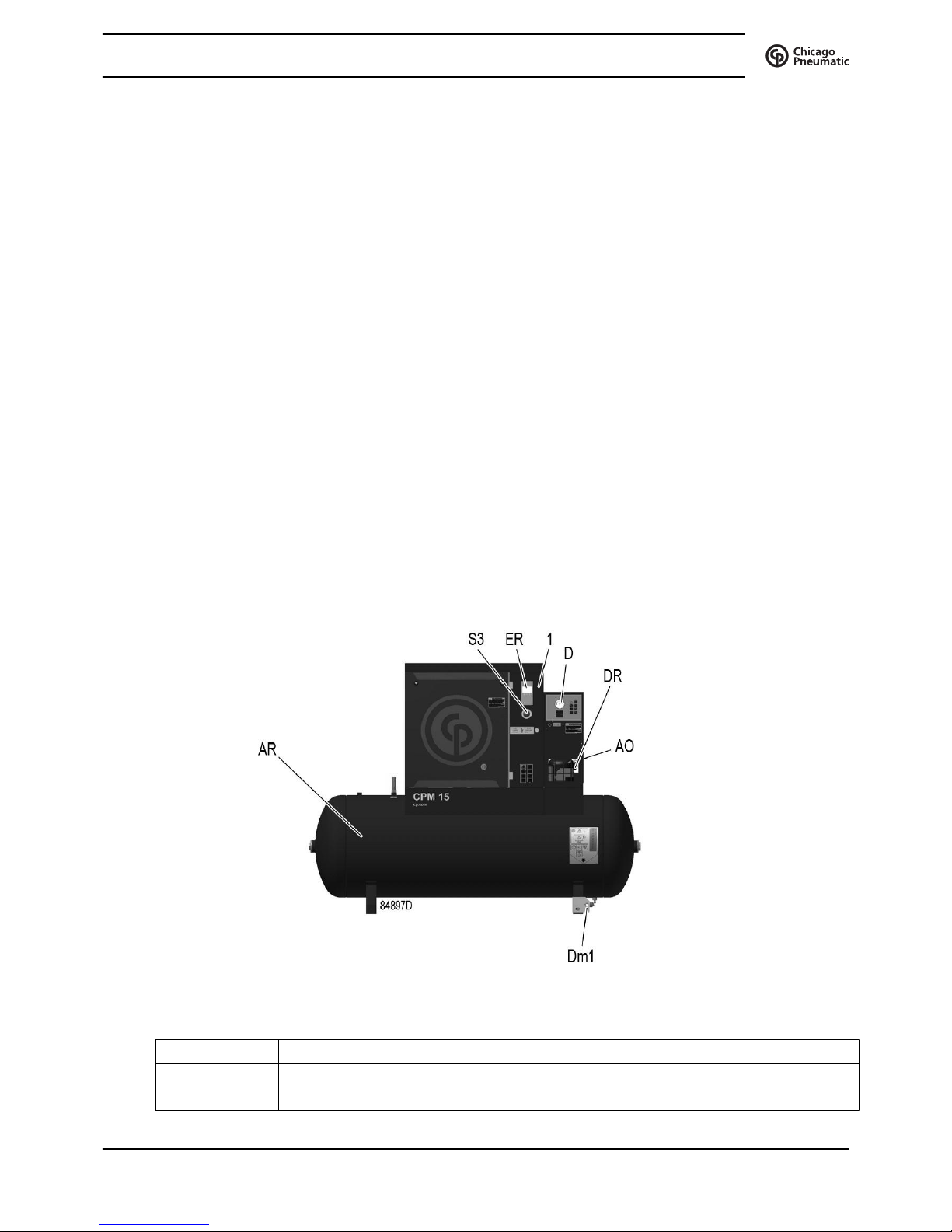
Front view, tank-mounted with dryer
Reference Designation
1 Electric cabinet
ER Controller
Instruction book
2920 7114 70 11
Reference Designation
S3 Emergency stop button
AO Air outlet
AR Air receiver
Dm1 Manual condensate drain
DR Dryer
D Dewpoint indicator (Only on units with dryer)
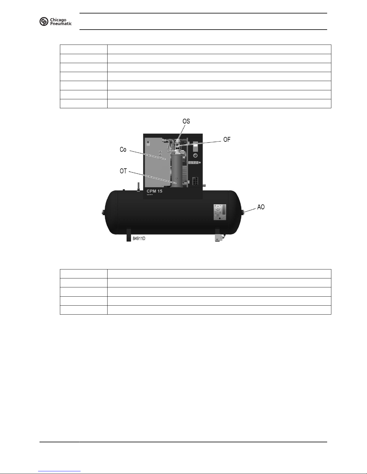
Front open view, tank-mounted
Reference Designation
Co Oil cooler
OF Oil filter
OS Oil separator
OT Oil separator tank
Instruction book
12 2920 7114 70
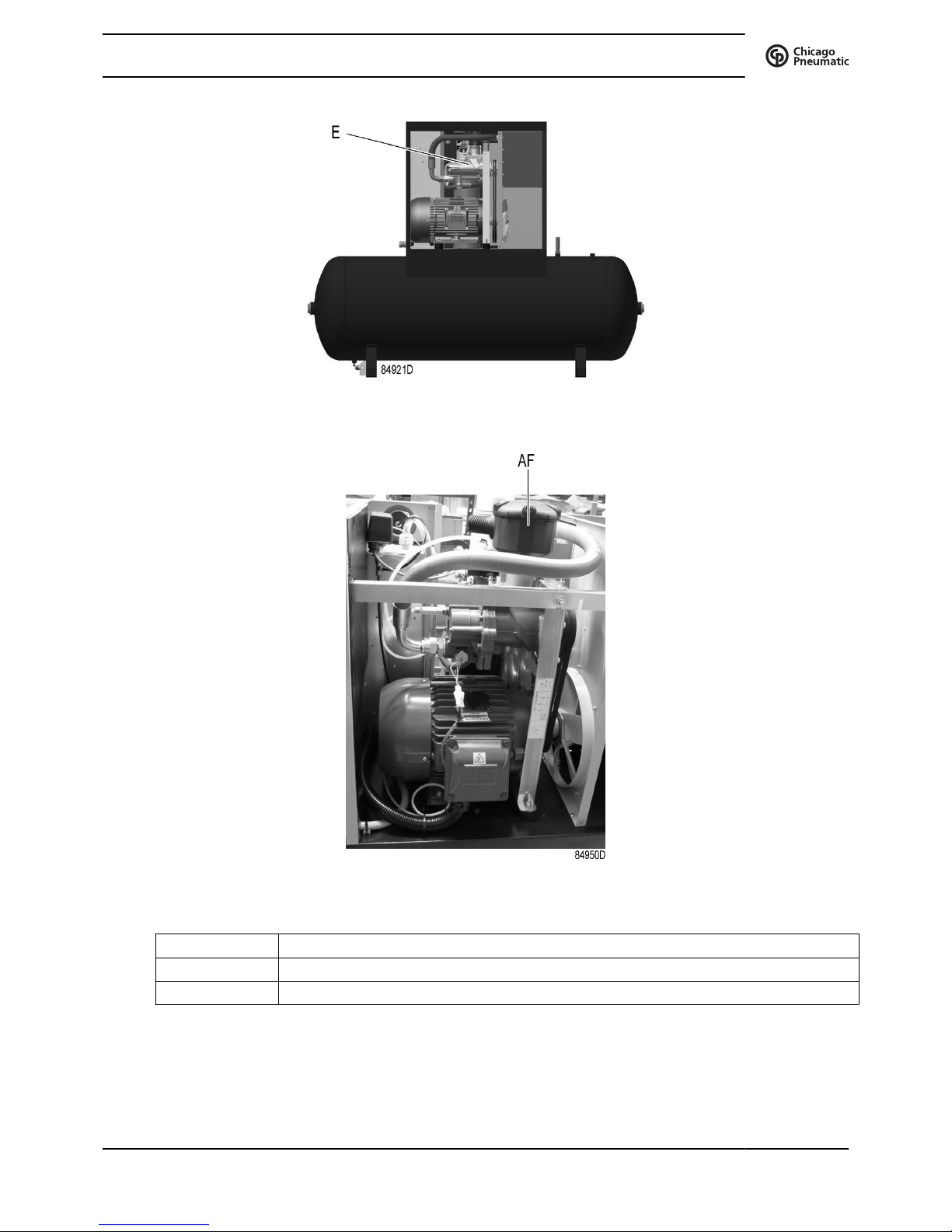
Rear open view, tank-mounted
Air filter
Reference Designation
E Compressor element
AF Air filter
Instruction book
2920 7114 70 13
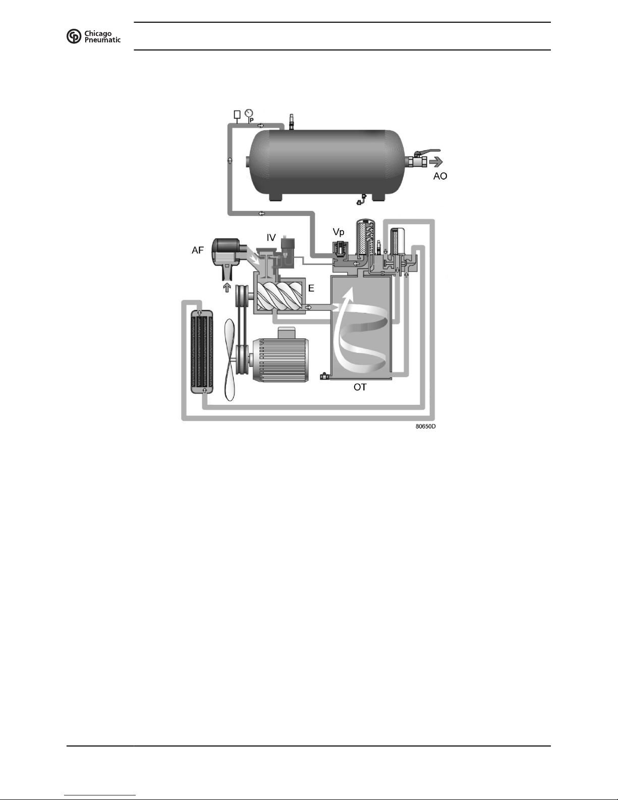
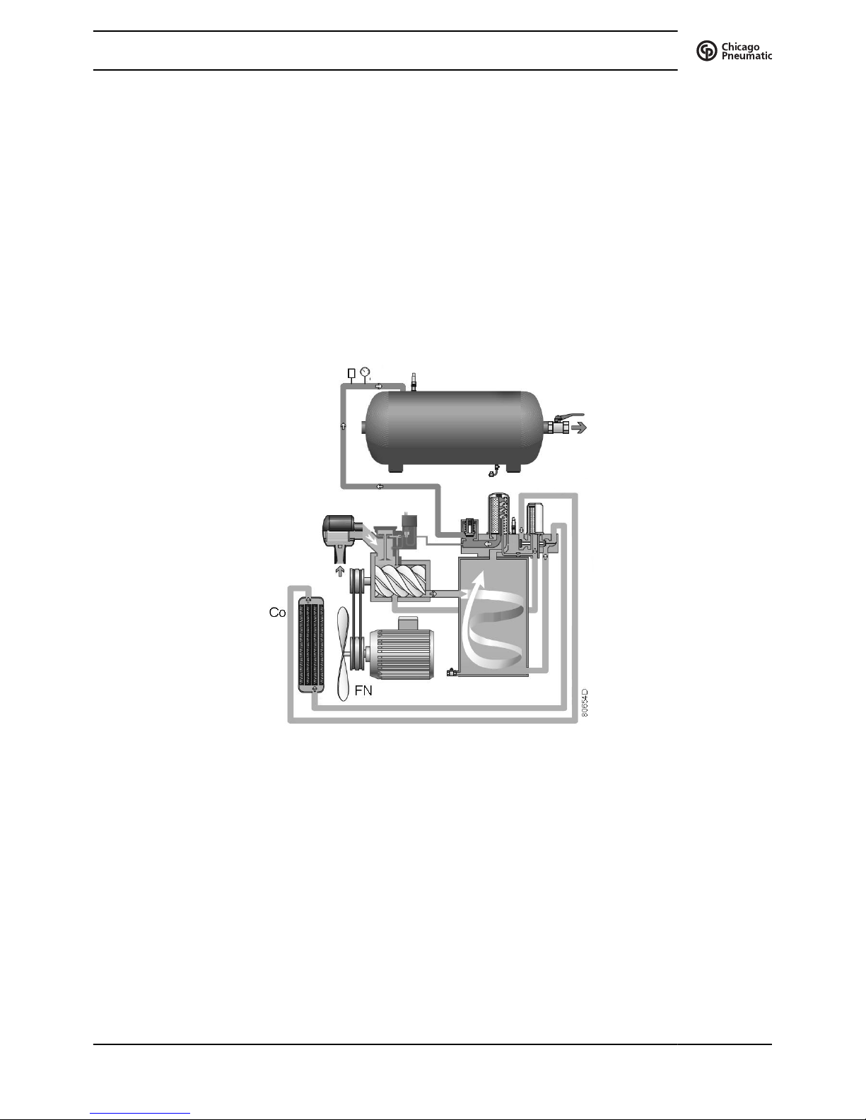
2.2 Air flow
Air flow, Tank-mounted
Air drawn through filter (AF) and open inlet valve (IV) into compressor element (E) is
compressed. Compressed air and oil flow into oil separator/tank (OT). The air is discharged via
minimum pressure valve (Vp) towards the air outlet (AO).
Instruction book
14 2920 7114 70
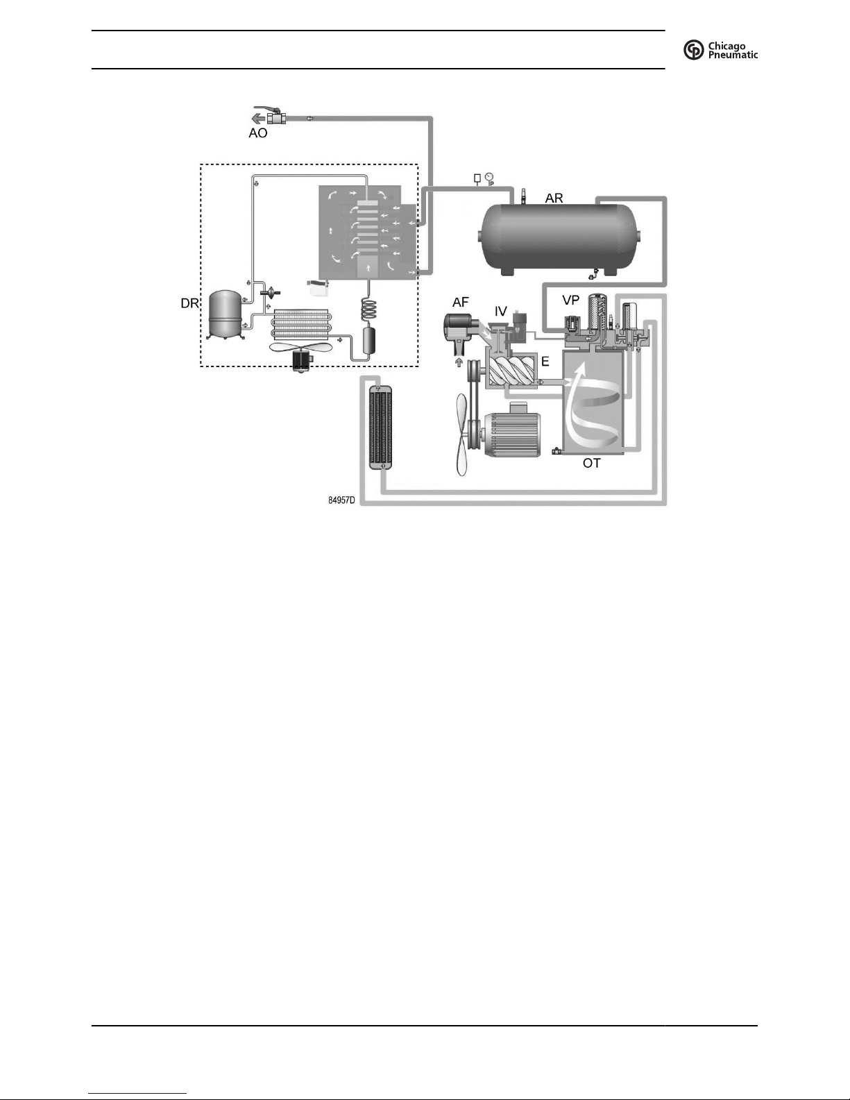
Air flow, Tank-mounted with dryer
Air drawn through filter (AF) and open inlet valve (IV) into compressor element (E) is
compressed. Compressed air and oil flow into oil separator/tank (OT). The air is discharged via
minimum pressure valve (Vp), air receiver (AR) and air dryer (DR) towards the air outlet (AO).
Instruction book
2920 7114 70 15
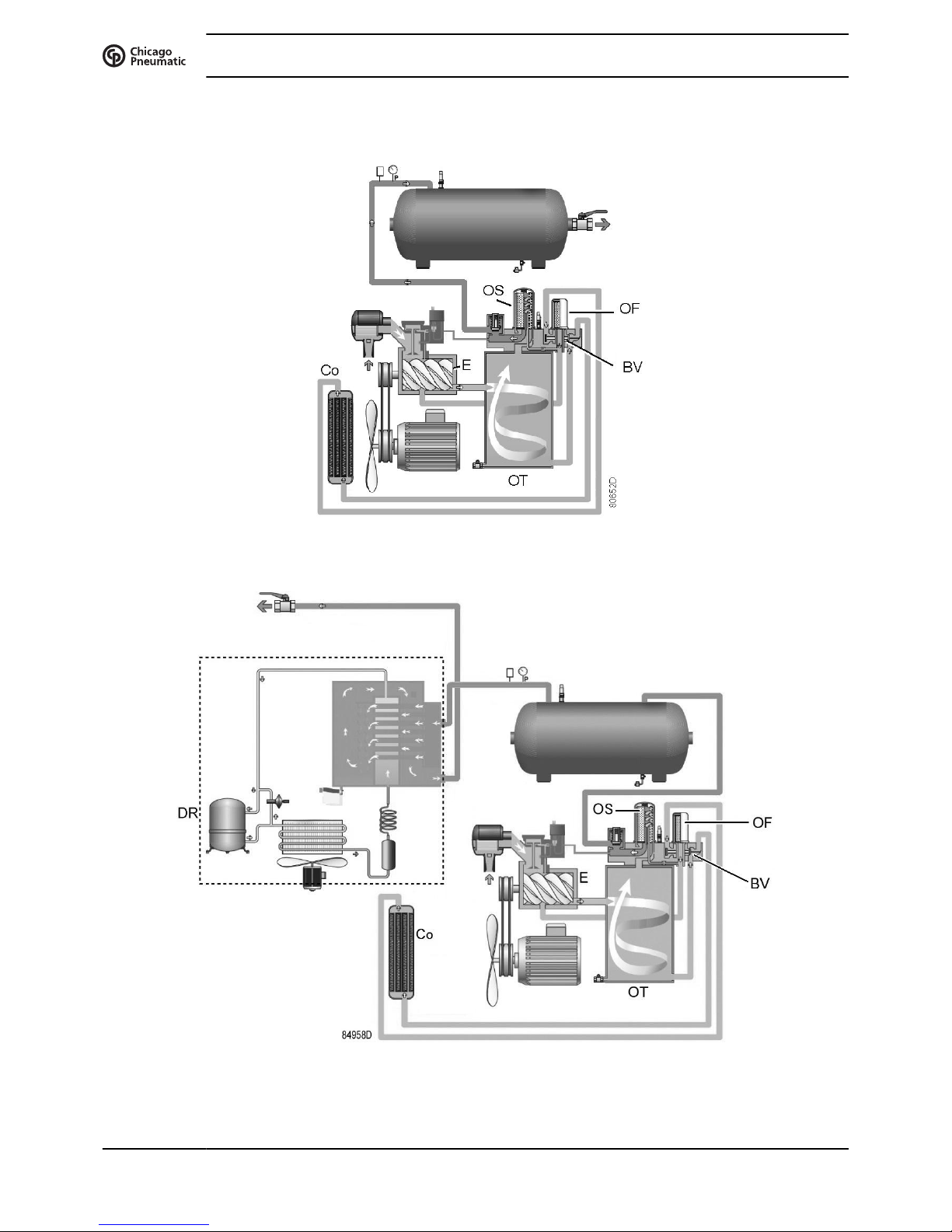
2.3 Oil system
Oil system
Oil system, units with dryer
Instruction book
16 2920 7114 70
Air pressure in the oil separator tank (OT) forces the oil from the tank to compressor element (E)
via oil cooler (Co) and oil filter (OF). Compressed air and oil flow into oil separator/tank (OT)
where most of the oil is separated from the air by centrifugal action. The remaining oil is removed
by oil separator (OS) and returns to the oil circuit via a separate line. The minimum pressure
valve (Vp - see section Air flow) ensures a minimal pressure in the tank, required for oil
circulation under all circumstances.
The oil system is fitted with a by-pass valve (BV). When the oil temperature is below the set-point
of the valve, the by-pass valve shuts off the oil supply from oil cooler. The by-pass valve starts
opening the supply from cooler (Co) when the oil temperature exceeds the setting of the valve.
The setting of the by-pass valve depends on the model. See the section Compressor data.
2.4 Cooling system
Cooling system
The cooling system comprises oil cooler (Co) and fan (FN). The fan, mounted directly onto the
motor shaft, generates the cooling air in order to cool the oil and the internal parts of the
compressor.
Instruction book
2920 7114 70 17
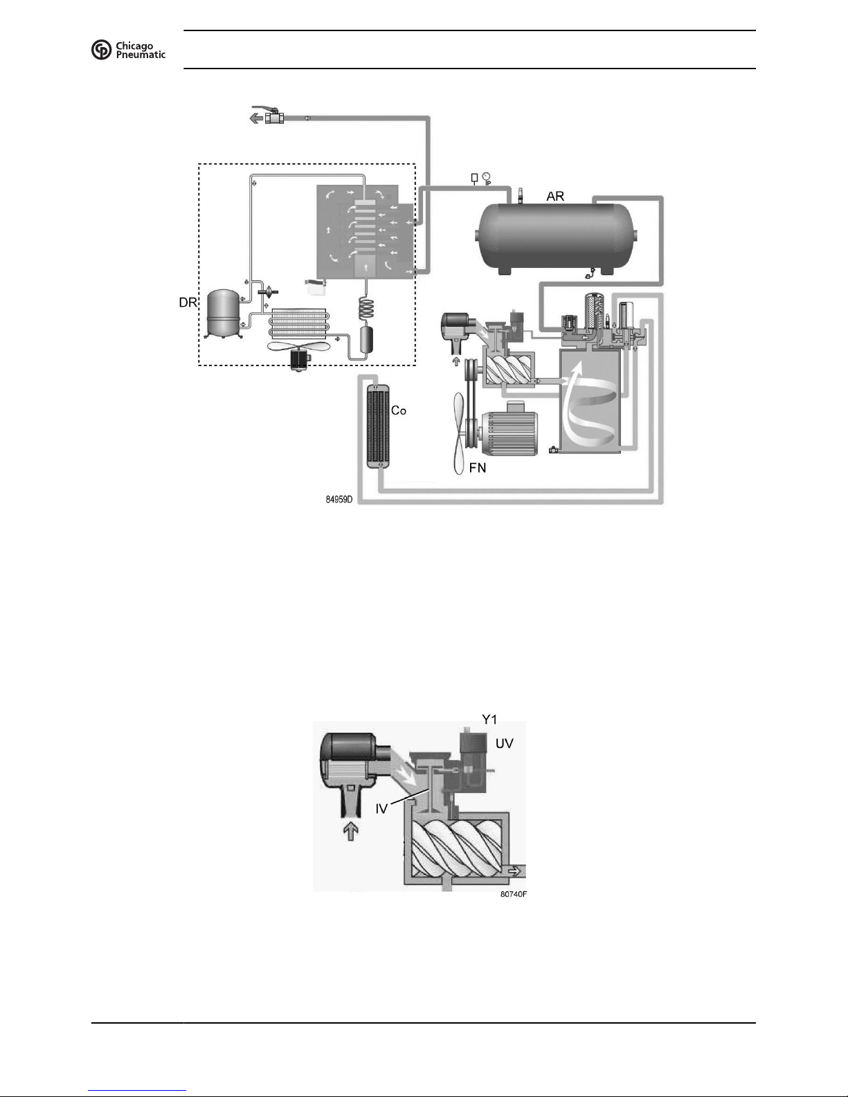
Cooling system, units with dryer
The cooling system of the version with dryer comprises oil cooler (Co), air receiver (AR) and fan
(FN).
The dryer (DR) has a separate cooling fan and an automatic condensate drain (see also section
Air dryer).
2.5 Regulating system
Detail view of unloader assembly (UA)
The main components of the regulating system are:
Instruction book
18 2920 7114 70

• Unloader (UA), including inlet valve (IV) and unloading valve (UV).
• Loading solenoid valve (Y1).
• The controller that regulates the compressor based on the pressure settings and readings of
the pressure sensor.
Loading
As long as the working pressure is below the preset maximum, the solenoid valve is energised,
allowing control air to the unloader: the inlet valve opens completely and the unloading valve
closes completely. The compressor will run fully loaded (100% output).
Anticipated restart algorithm:
The unit stops loaded, because the set ‘Unload’ pressure is reached. The controller will anticipate
the restart 0,2 bar before reaching the set ‘Load’ pressure to avoid a restarting delay. Otherwise
this may result in a restarting pressure lower than the set ‘Load’ pressure.
Unloading
When the working pressure reaches the maximum limit, the solenoid valve is de-energised,
venting the control air: the inlet valve closes completely and the unloading valve opens
completely. The compressor will run unloaded (0% output).
The compressors are equipped with an intelligent controller that will stop the compressor after a
variable period of unloaded operation using following control algorithm:
• At power on, in the first work cycle, the ‘Unload’ period is 30 seconds.
• After the first work cycle, and in all other working cycles, the ‘Unload’ period is calculated
following 3 rules:
a. Given a max number of 10 restarts per hour (factory setting), the total running period
per cycle (‘Load’ time + ‘Unload’ time) must be minimum 6 minutes (360s).
b. At the end of the unload period the controller checks the air consumption and decides
whether to stop the unit or restart to anticipate the air demand.
c. Motor virtual temperature calculation.
If the unit is restarting frequently, or is manually restarted by the operator, the controller
will extend the unload period in order to ensure proper motor cooling. This point
overrules point the standard unload period.
The compressor will automatically restart when the net pressure drops to the minimum limit.
2.6 Control panel
Instruction book
2920 7114 70 19
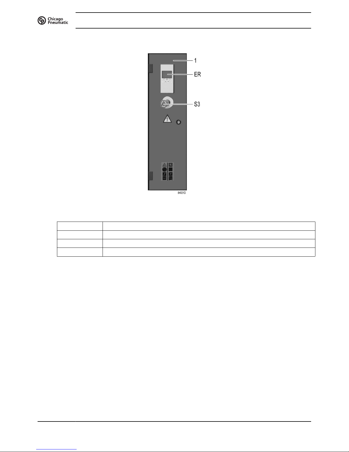
Control panel
Control panel
Reference Designation
1 Electric cabinet
ER ES 4000 Basic Controller
S3 Emergency stop button
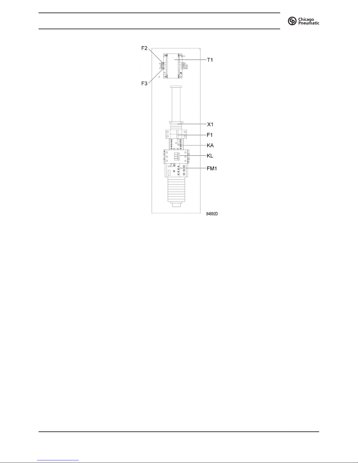
2.7 Electrical system
Electrical components
The electrical system comprises following components:
Instruction book
20 2920 7114 70
Electric cubicle UL (DOL)
Instruction book
2920 7114 70 21

Electric cubicle UL(YD)
Reference Designation
F1 Primary fuse, transformer of the control circuit
F2–3 Fuses
FM1 Motor overload relay
KA Auxiliary circuit relay
KD Delta contactor
KL Line contactor
KY Star contactor
T1 Transformer
X1 Terminal block of the control circuit
X2 Terminal block, voltage change of the motor (Only on tri-voltage units)
Electrical diagram
2205 0315 60 Service diagram cULus/ cCSAus (DOL) for 10 and 15 hp
2205 0316 30 Service diagram cULus/ cCSAus (YD) for 20 hp
The complete electrical diagram can be found in the electric cubicle.
The complete electrical diagram can be found on the CD supplied with the machine.
Instruction book
22 2920 7114 70
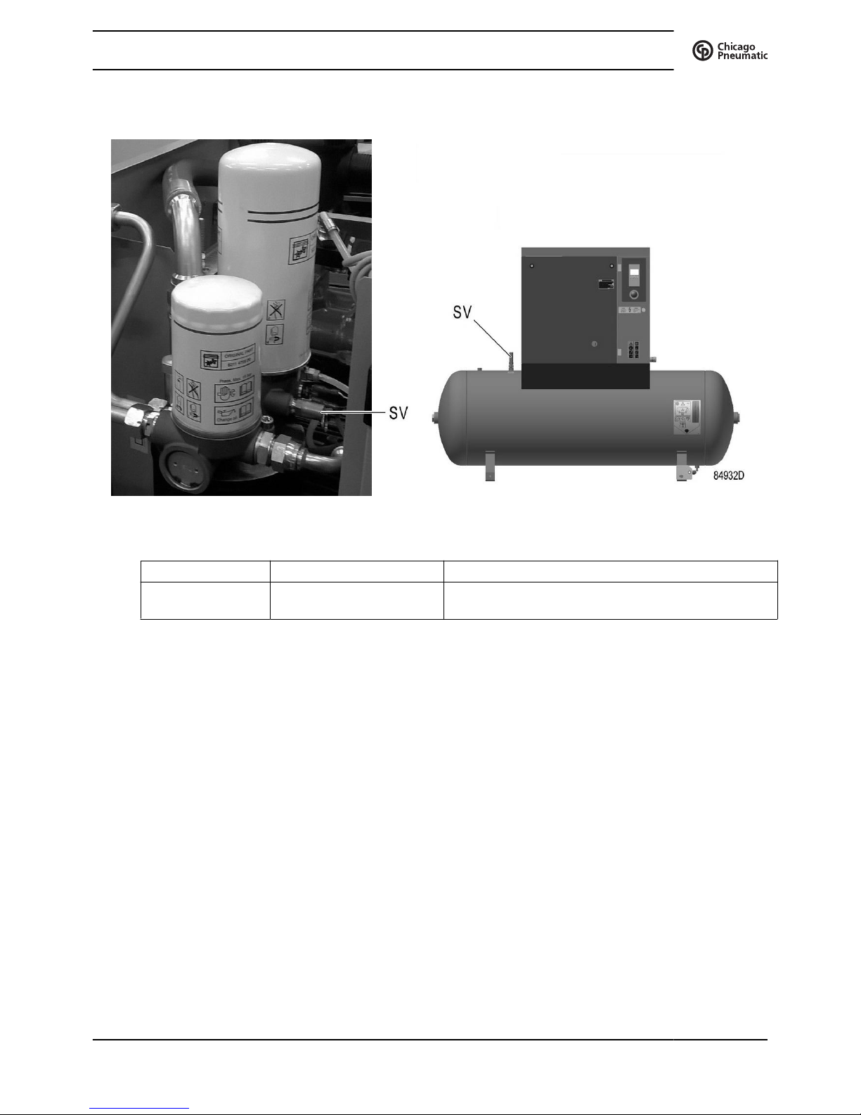
2.8 Protection of the compressor
Safety valve on the compressor and on the vessel
Reference Designation Function
SV Safety valve To protect the air outlet system if the outlet pressure
exceeds the opening pressure of the valve.
Instruction book
2920 7114 70 23

2.9 Air dryer
Air Dryer
Wet compressed air enters the dryer and is further cooled by the outgoing, dried air (2). Moisture
in the incoming air condenses. The air then flows through heat exchanger (1) where refrigerant
evaporates, withdrawing heat from the air. The cold air then flows through condensate trap (4)
which separates condensate from the air. The condensate is automatically drained. The cold,
dried air then flows through heat exchanger (3), where it is warmed up by the incoming air.
Instruction book
24 2920 7114 70
 Loading...