

Chicago Pneumatic CPF 175, CPF 200, CPVS 200, CPVS 250 Instruction Manual
Instruction Manual EN
CP COMPRESSOR
Model CPF 175 - 200
CPVS 200 - 250
62 305 799 65
CPVS 250
CPF 200

11/2008
Page 2
Chicago Pneumatic Compressors
62 305 799 65
The CP COMPRESSOR should never be operated beyond its capabilities
or in any way which does not comply with the instructions contained
in this operating and maintenance guide.
Chicago Pneumatic Compressors will decline any responsibility
if these instructions are not respected.
This equipment has been factory tested and satisfies normal
operating conditions: they must not be exceeded
as this would place the machine under abnormal stress and effort.
INSTALLATION INSTRUCTIONS
For the guarantee to be valid, the unit must be assembled in covered
premises with temperatures not exceeding :
Mini: + 36 °F (frost free)
Maxi: + 104 °F
You must also have:
3,33 ft space around the compressor
-
low ventilation (fresh air) proportionate to the ventilation flow necessary for the machine and protected
from any infiltration of humidity (splashes of water during bad weather) and all pollution
-
top insulation or extraction to ensure reversal of the flow of warm air and evacuation of the heat to
outside the equipment room
-
a link from the condensation water evacuation pipe to the drain discharger.
-
In case of dusty ambient environment, a pre-filtration is made by micro-filter on the air inlet of the room used for cooling and
perhaps a special filter on the compressor air inlet.
TECHNICAL CHARACTERISTICS
STANDARD MACHINES
CPF 175 200
Nominal pressure at full capacity PSI 100 125 150 175 100 125 150 175
Real flow*
(as per ISO 1217 ed 1996) cfm 865 820 744 603 1011 966 876 729
Motor power hp 175 200
Ø Pressure outlet (F) Inch 3" PN16 DN80 3" PN16 DN80
Oil receiver capacity gal 23,7 23,7
Residual quantity of oil ppm 3 3
Noise level at 3,3 ftdB(A) 73 74
(according to PNEUROP PN 8 NT C2)
* Suction pressure : 14.5 PSI absolute - Relative humidity : 0 % - Ambient temperature : 68 °F
- Effective delivery pressure : 102 PSI, 109 PSI, 138 PSI or 181 PSI (effective)
Dimensions (in) L x w x h 104,9x58,6x76,3 111,8x63,3x78,4
Approximate weight (Air) lbs 5655 6239

Chicago Pneumatic Compressors
62 305 799 65
11/2008
Page 3
CPF 175 200
Motor power (hp) 175 200
Main Voltage 460 Volt / 3 / 60 Hz
Nominal current (460V) (A) - -
Power supply cable H 07 300 Kcmil 350 Kcmil
Fuse protection (RK5) 250 A 300 A
Connection of the electric controler to an external control box
• Install an RC filter on the KM1 coil.
• Install an RC filter on the KM2 coil.
• All connections between external parts and the compressor must be carried out using a shielded cable, which must be earthed at one of its
ends.
WARNING: the operation connection cables between the different elements must never follow the same path as the existing power
cords. A separate installation from the power cords must be carried out.
• Install an RC filter on all the relay coils of the external operation units.
TECHNICAL CHARACTERISTICS
VARIABLE SPEED MACHINES
CPVS 200 250
Nominal pressure at full capacity PSI 79 101 138 87 101 138
Real flow* cfm 952 937 829 1076 1071 950
(as per ISO 1217 ed 1996)
Motor power hp 200 250
Ø Pressure outlet (F) Inch 3" PN16 DN80 3" PN16 DN80
Oil receiver capacity gal 23,7 23,7
Residual quantity of oil ppm 3 3
Noise level at 3,3 ft (air) dB(A) 76 76
(according to PNEUROP PN 8 NT C2)
* Suction pressure : 14.5 PSI absolute - Relative humidity : 0 % - Ambient temperature : 68 °F
- Effective delivery pressure : 102 PSI, 109 PSI, 138 PSI or 181 PSI (effective)
Dimensions (in) L x w x h 107,6x58,6x76,3 115,8x63,3x78,4
Approximate weight (Air) lbs 6613 8113
Note : For specific information on variable speed machines see Chapter 6.

11/2008
Page 4
Chicago Pneumatic Compressors
62 305 799 65
CONTENTS
Space requirement and installation diagram CPF 175 - CPVS 200 (Air cooled) .............................................................................. 6
Space requirement and installation diagram CPF 200 - CPVS 250 (Air cooled) .............................................................................. 7
Chapter 1 - Description ................................................................................................................................................................................. 8
A - General Information ...................................................................................................................................................................... 8
B - Respect of the environment and prevention of pollution ............................................................................................................. 8
C - Standard equipment ...................................................................................................................................................................... 8
D - Definition of the pictograms ........................................................................................................................................................ 8
E - Electronic board ............................................................................................................................................................................ 8
Chapter 2 - Installation ................................................................................................................................................................................. 9
A - Handling ....................................................................................................................................................................................... 9
B - Room ............................................................................................................................................................................................ 9
C - Assembly....................................................................................................................................................................................... 9
D - Air discharge pipes ....................................................................................................................................................................... 9
E - Electric cabling ........................................................................................................................................................................... 10
Chapter 3 - Commissioning ........................................................................................................................................................................ 11
A - Preparation for start-up ............................................................................................................................................................... 11
B - First start-up ............................................................................................................................................................................... 11
C - Discharge pressure adjustment ................................................................................................................................................... 11
D - Parallel compressor assembly ..................................................................................................................................................... 11
E - Safety .......................................................................................................................................................................................... 11
Chapter 4 - Operation ................................................................................................................................................................................. 12
A - Air and oil circuits ...................................................................................................................................................................... 12
B - Regulation principles .................................................................................................................................................................. 13
Chapter 5 - Options ..................................................................................................................................................................................... 14
A - Level detection bleed valve (Fig. 12) ......................................................................................................................................... 14
B - Advanced filtration to the compression air inlet (Fig. 13a and 13b) .......................................................................................... 14
C - Pre-filtration panels (Fig. 14 and 15) ......................................................................................................................................... 15
D - Automatic restarting ................................................................................................................................................................... 16
E - Remote starting and stopping ..................................................................................................................................................... 16
F - Special oils .................................................................................................................................................................................. 16
G - Centrifugal separator (see B chapter 1) ...................................................................................................................................... 16
H - Condensate drain pipes .............................................................................................................................................................. 16
Chapter 6 - Specific information for CPVS 200 - 250 ............................................................................................................................. 17
A - Description (cf Chap. 1) ............................................................................................................................................................. 17
B - Safety .......................................................................................................................................................................................... 17
C - Installation .................................................................................................................................................................................. 17
D - Commissioning ........................................................................................................................................................................... 18
E - Operating incidents ..................................................................................................................................................................... 20
Chapter 7 - Maintenance ............................................................................................................................................................................ 21
A - Oil level and change ................................................................................................................................................................... 21
B - Oil return (Fig. 22) ..................................................................................................................................................................... 22
C - Air filter (see B chapter 1) .......................................................................................................................................................... 22
D - Fan .............................................................................................................................................................................................. 23
E - Oil and air cooler ........................................................................................................................................................................ 23
F - Oil separator (see B chapter 1) ................................................................................................................................................... 23
G - Draining condensation water (see B chapter 1) ......................................................................................................................... 24
H - Motors ........................................................................................................................................................................................ 24
I - Coupling ..................................................................................................................................................................................... 24
J - Suction control system (see Fig. 25) .......................................................................................................................................... 24
K - Temperature safety tests ............................................................................................................................................................. 24
L - Refastening electric connections ................................................................................................................................................. 24
M -Decommissioning the compressor at the end of its useful life ................................................................................................... 24

Chicago Pneumatic Compressors
62 305 799 65
11/2008
Page 5
CONTENTS
Chapter 8 - Trouble shooting ...................................................................................................................................................................... 25
A - Main incidents ............................................................................................................................................................................ 25
Chicago Pneumatic Compressors
62 305 799 65
11/2008
Page 6
4.76
1.96
3.34
3.34
30.19
76.29
4.84
45.07
15.11
15.07
7.24
12.91 12.91
3.93
0.39
0.39
7.4 7.4
Ø0.78
3.14
3.11
3.18
24.4027.32 24.40
*
9.52
58.66
98.58
30 24.56
3.7
50.62
65.5
7.08
33.70
22.99
4.17
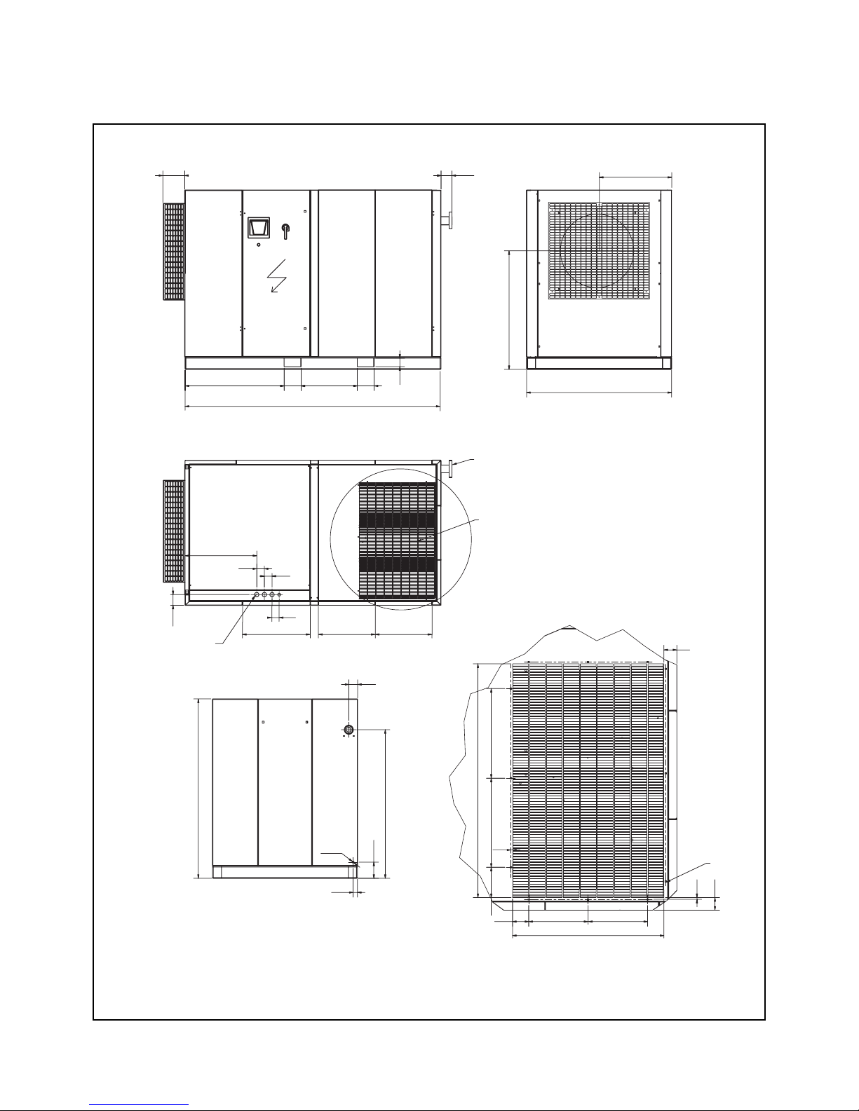
Space requirement and installation diagram CPF 175 - CPVS 200 (Air cooled)
(see page 2 - installation instructions)
Fig. 1
Air delivery
Air inlet side
Cooling air outlet
Electric power
diam. 1.88x3 +
diam. 1.45
* Hole 0.32x0.32
Dimensions for outlet duct
Chicago Pneumatic Compressors
62 305 799 65
11/2008
Page 7
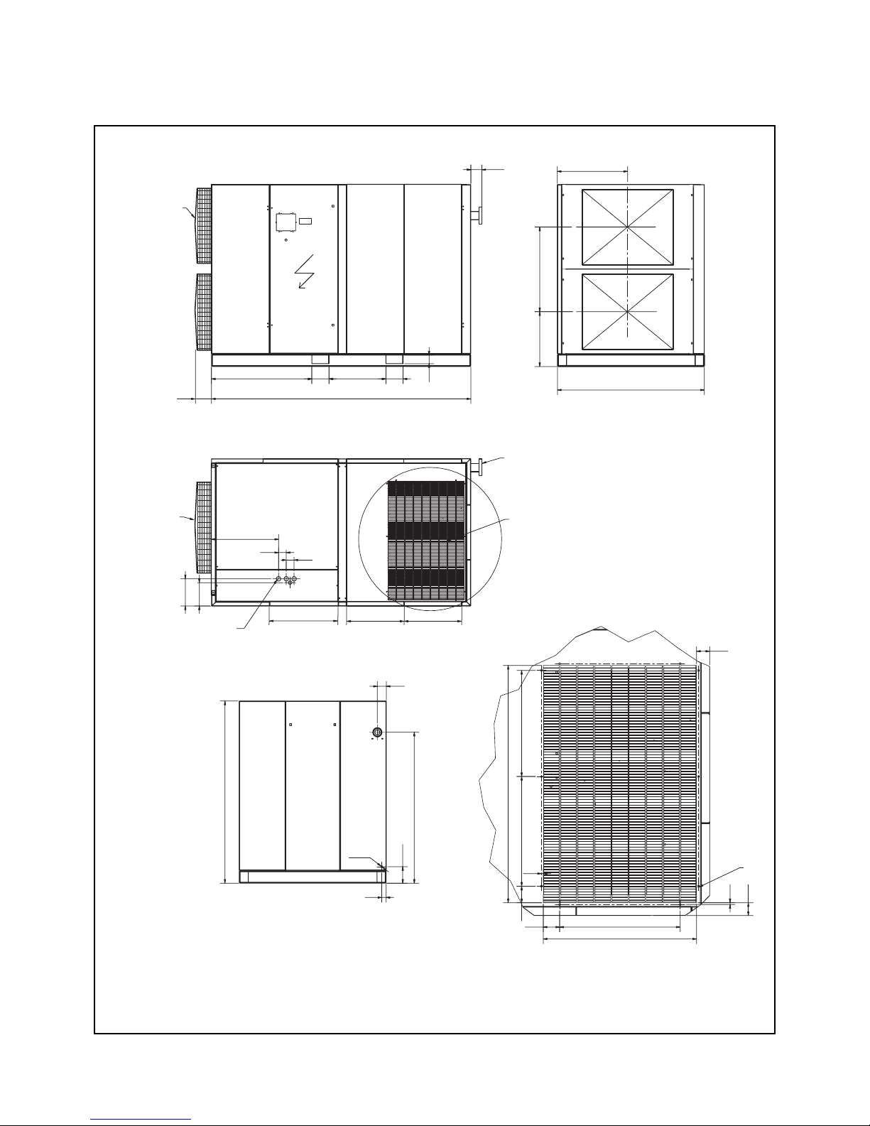
Space requirement and installation diagram CPF 200 - CPVS 250 (Air cooled)
(see page 2 - installation instructions)
Fig. 2
4.76
1.96
0.33
0.33
30.31
78.42
4.33
51.08
22.83
23.62
3.54
25.98
3.54
0.39
0.39
7.40 7.40
Ø0.78
29.33
2.75
2.83
24.64 24.64
*
62.38
111.89
43.30 24.56
94
36.4123.62
64.96
7.08
33.07
1.14
11.71
10.05
4.72
Air delivery
Air inlet
Air inlet side
Cooling air outlet
Electric power
diam. 1.88x3 +
diam. 1.45
* Hole 0.32x0.32
Dimensions for outlet duct
Pre-filtering
option standard
on the CPVS 250

Chicago Pneumatic Compressors
62 305 799 65
11/2008
Page 8
Chapter 1 - Description
A - General Information
The Chicago Pneumatic Compressors air compressor CPF, CPVS
model, constitute a central compressed air which is fully equipped
and tested, driven by an electric motor and enclosed by a soundproof cover, necessary to keep the entire apparatus cool.
The compression element is a single-stage, oil-refrigerated, rotary
screw compressor. The oil is stored in a vertical tank, which is
fitted with an oil separator.
The compression element and the motor are fixed to the frame
using silent blocks.
B - Respect of the environment and
prevention of pollution
1 - Maintenance of the machine
Make sure that the used components of the machine (waste oil,
oil and air filters, oil separators, etc.) are disposed of according
to national and local regulations.
2 - Condensate bleed pipe (optional)
Make sure that the condensates (water, oil) are drained and treated
according to national and local regulations.
3 - Water cooled machines
For this type of machine, when the cooling circuit is made of an
open circuit, a hydrocarbons filter is recommended after passing
through the cooler, particularly for installations located in
ecologically sensitive areas.
4 - End of life of the machine
Make sure that the machine as a whole is disposed of according
to national and local regulations. ( Refer Chapter 7 - M )
C - Standard equipment
In its standard version, the covered unit includes:
- Operating components:
1. A twinned screw-type compressor.
2. An electric motor: 1500 rpm, short-circuit rotor, 460 V
voltage according to the model.
3. Star-Delta starting (or inverter).
4. Gear drive with elastic coupling linking the motor to the
compressor.
5. Air and oil tank in compliance with applicable legislation
ASME.
6. Flow rate control by cut-off of suction.
7. A greasing system using the circuit's differential pressure,
thus avoiding the need for an oil pump.
8. An oil separation system by oil separator filter.
9. A heat evacuation system :
- forced-air ventilation for air-cooled units,
- heat exchanger for water-cooled units.
10. A dry air filter.
11. Oil filters.
12. A command and control electronic board.
- Safety devices:
1. A safety valve mounted on the oil receiver.
2. An thermal protection device for the motor, situated in the
starting box, to protect the motor from excessive over-load.
3. An air temperature sensor that stops the compressor when
the temperature rises abnormally or during an oil cooling
defect.
- Control devices:
1. A minimum pressure valve located at the oil tank outlet,
just beyond the oil separator, which guarantees minimum
pressure in the lubrication circuit.
2. Automatic draining allowing the unit to be exposed to the
atmosphere when stopping to thus ensure empty start up
which relieves the motor,
3. An oil level indicator situated on the front side of the tank
( see fig. 21).
4. An electronic controller including:
– a control keyboard,
– the main safety and control indications.
5. The pressure sensor ensures control over the compressed
air flow.
The CP compressed air unit has been designed, produced and
tested in accordance with the following recommendations, codes
and standards :
- machine safety: European Directive 98/37/CE, 91/368/CEE and
93/68/CEE.
- pressure vessels: European Directive for simple pressure vessels
n° 87/404/CEE.
- electrical equipment:
• electrical equipment: European Directive Low tension
73/23/CEE.
• electromagnetic compatibility European Directive: 89/336/CEE,
92/31/CEE.
- performance levels: ISO 1217 : 1996.
- noise level : PNEUROP PN 8 NT C2.
- European Directive 97/23/EC
" Pressure Equipment Directive ".
D - Definition of the pictograms
Typical examples of pictograms valid for CP compressors:
1. Water outlet
2. Manual condensation water draining
3. Water inlet
4. Automatic condensation water draining
5. Unplug and decompress the compressor
before maintenance
12
34 5
E - Electronic board
See the specific instructions for a description of the electronic
controler, together with operating instructions:
Notice N° 62 305 516 99 for version Standard
Notice N° 62 305 517 99 for version CPVS
Chicago Pneumatic Compressors
62 305 799 65
11/2008
Page 9
Chapter 2 - Installation
A - Handling
The CP Compressors must always be handled with care. It may
be lifted either with a forklift truck or by means of a travelling
crane. In the latter case, precautions must be taken in order not to
damage the unit's canopy.
B - Room
The CP Compressors is designed to operate in a frost-free
environment, supplied with air at a temperature of no more than
104 °F. The premises must be well-aired and as close as possible
to the place where the compressed air is used. A space must be
left around the unit, for cleaning and maintenance purposes. It is
very important for the compressor to have an abundant supply of
fresh air. (see page 2).
COMMENT
When the atmosphere is contaminated by organic or mineral dust or
by corrosive chemical emanations the following precautions must be
taken:
1. Provide another air inlet as close as possible to the
compressor suction.(recommendation which is valid if the
only room available is excessively damp).
2 - Use an additional air supply filter. Consult us.
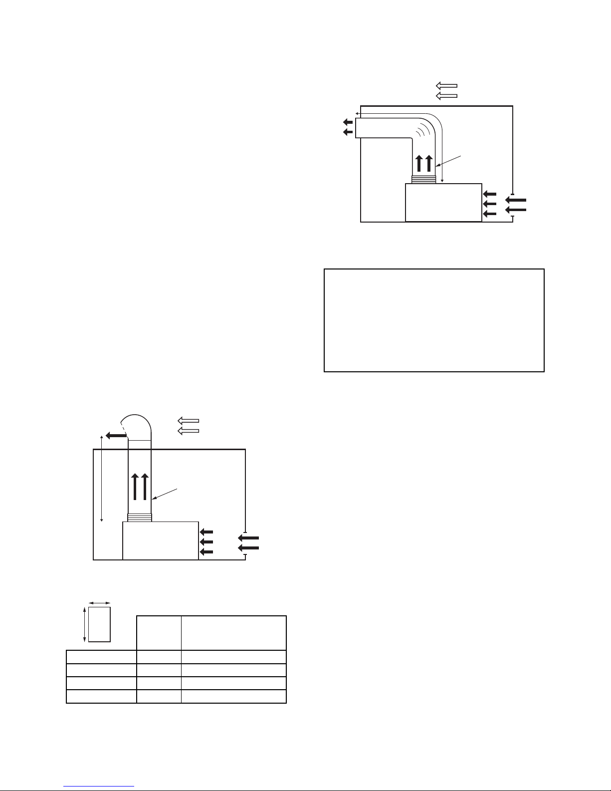
Installation with heat dispersion sleeve
If the operation of the compressor increases the ambient
temperature above 104°F, it is necessary to discharge the hot air
leaving the cooler to the exterior by means of a sleeve.
L
V
Fig. 5a - Sleeve with roof outlet
L
V
Fig. 5b - Sleeve with an elbow
V maxi = 18,04 ft/s
(Ratio of volume flow rate of the ventilation to the sleeve
cross section)
L maxi = 32.8 ft (without mechanical extractor)
Cross section of room air inlet > 2 x Duct outlet cross section
2 elbows accepted with large radius of curve and fluid gui-
dance vanes
Ratio (Length/Width of sleeve) maxi = 1.6
Make sure that no outside air, especially if humid, can be fed
back into the machine and damage electric and electronic
components or rust metal parts.
The maximum admissible pressure loss of the sleeve should not
exceed 30 Pa (3 mmCE). In case of higher value, provide an
additional ventilation (mechanical extractor) with a flow
equivalent to that of the machine, C1 converter controlled (see
electrical diagram).
Regulation type 0-10V
0V extractor shutdown
10V full rate operation
C - Assembly
Put the unit on a stable surface. The CP does not need foundations.
Any flat surface that can support their weight will be sufficient
(industrial floor).
D - Air discharge pipes
The diameter of the air discharge pipe must be at least 3" gas for
the CPF 175/200 and CPVS 200/250.Current legislation requires
that a valve which is lockable in the closed position be installed
at the air box outlet, connected to the compressor by a union
and flexible line to allow it to be cut off during repair work.
Prevailing wind
Flexible fitting
Compressor
Flexible fitting
Compressor
Prevailing wind
Ventilation Duct minimum cross section
flow rate ( d ≤ L ≤ 1,6d )
cfm sqm
CPF 175 11780 10.87
CPVS 200 16485 15.22
CPF 200 16485 15.22
CPVS 250 16485 15.22
d
L
 Loading...