

Chicago Pneumatic CPF 270, CPF 340 Instruction Book

CPF 270, CPF 340
Instruction book


Chicago Pneumatic
CPF 270, CPF 340
Instruction book
Original instructions
Copyright Notice
Any unauthorized use or copying of the contents or any part thereof is prohibited.
This applies in particular to trademarks, model denominations, part numbers and drawings.
This instruction book is valid for CE as well as non-CE labelled machines. It meets the
requirements for instructions specified by the applicable European directives as identified
in the Declaration of Conformity.
2013 - 02
No. 2920 1796 01
www.cp.com

Instruction book
Table of contents
1 Safety precautions..........................................................................................................5
1.1 SAFETY ICONS...................................................................................................................................5
1.2 SAFETY PRECAUTIONS, GENERAL...........................................................................................................5
1.3 SAFETY PRECAUTIONS DURING INSTALLATION...........................................................................................6
1.4 SAFETY PRECAUTIONS DURING OPERATION..............................................................................................7
1.5 SAFETY PRECAUTIONS DURING MAINTENANCE OR REPAIR...........................................................................8
2 General description......................................................................................................10
2.1 INTRODUCTION.................................................................................................................................10
2.2 COOLING AND CONDENSATE SYSTEM....................................................................................................11
2.3 REGULATING SYSTEM........................................................................................................................12
3 Electronic regulator......................................................................................................14
3.1 ELECTRONIC CONTROL SYSTEM...........................................................................................................14
3.2 CONTROL PANEL..............................................................................................................................16
3.3 ICONS USED....................................................................................................................................17
3.4 MAIN SCREEN..................................................................................................................................20
3.5 CALLING UP MENUS..........................................................................................................................23
3.6 INPUTS MENU...................................................................................................................................24
3.7 OUTPUTS MENU...............................................................................................................................26
3.8 COUNTERS......................................................................................................................................28
3.9 CONTROL MODE SELECTION................................................................................................................30
3.10 SERVICE MENU................................................................................................................................31
3.11 SETPOINT MENU...............................................................................................................................35
3.12 EVENT HISTORY MENU.......................................................................................................................37
3.13 MODIFYING GENERAL SETTINGS...........................................................................................................38
3.14 INFO MENU......................................................................................................................................43
3.15 WEEK TIMER MENU...........................................................................................................................44
2 2920 1796 01

Instruction book
3.16 TEST MENU.....................................................................................................................................54
3.17 PROGRAMMABLE SETTINGS.................................................................................................................55
4 Installation.....................................................................................................................59
4.1 DIMENSION DRAWING........................................................................................................................60
4.2 INSTALLATION PROPOSAL...................................................................................................................63
4.3 ELECTRIC CABLE SIZE.......................................................................................................................67
4.4 PICTOGRAPHS.................................................................................................................................69
4.5 COOLING WATER REQUIREMENTS.........................................................................................................70
5 Operating instructions.................................................................................................75
5.1 INITIAL START-UP..............................................................................................................................75
5.2 BEFORE STARTING............................................................................................................................79
5.3 STARTING.......................................................................................................................................80
5.4 DURING OPERATION..........................................................................................................................81
5.5 CHECKING THE DISPLAY.....................................................................................................................82
5.6 STOPPING.......................................................................................................................................83
5.7 TAKING OUT OF OPERATION................................................................................................................84
5.8 USE OF AIR RECEIVER.......................................................................................................................85
6 Maintenance..................................................................................................................86
6.1 PREVENTIVE MAINTENANCE SCHEDULE..................................................................................................86
6.2 MOTORS.........................................................................................................................................87
6.3 OIL SPECIFICATIONS..........................................................................................................................89
6.4 OIL CHANGE....................................................................................................................................89
6.5 OIL FILTER CHANGE..........................................................................................................................93
6.6 STORAGE AFTER INSTALLATION...........................................................................................................95
6.7 SERVICE KITS..................................................................................................................................95
6.8 DISPOSAL OF USED MATERIAL.............................................................................................................96
7 Adjustments and servicing procedures.....................................................................97
2920 1796 01 3

Instruction book
7.1 AIR FILTERS....................................................................................................................................97
7.2 COOLERS.......................................................................................................................................98
7.3 SAFETY VALVE.................................................................................................................................99
8 Problem solving..........................................................................................................101
8.1 PROBLEM SOLVING.........................................................................................................................101
9 Technical data.............................................................................................................103
9.1 READINGS ON DISPLAY....................................................................................................................103
9.2 REFERENCE CONDITIONS.................................................................................................................103
9.3 LIMITS..........................................................................................................................................104
9.4 SETTINGS OF SAFETY VALVE.............................................................................................................104
9.5 SETTINGS FOR OVERLOAD RELAY AND FUSES.......................................................................................105
9.6 SETTINGS OF CIRCUIT BREAKERS.......................................................................................................107
9.7 COMPRESSOR DATA........................................................................................................................109
10 Pressure equipment directives.................................................................................115
11 Declaration of conformity..........................................................................................117
4 2920 1796 01
Instruction book
1 Safety precautions
1.1 Safety icons
Explanation
Danger for life
Warning
Important note
1.2 Safety precautions, general
General precautions
1. The operator must employ safe working practices and observe all related work safety requirements and
regulations.
2. If any of the following statements does not comply with the applicable legislation, the stricter of the two
shall apply.
3. Installation, operation, maintenance and repair work must only be performed by authorized, trained,
specialized personnel.
4. The compressor is not considered capable of producing air of breathing quality. For air of breathing quality,
the compressed air must be adequately purified according to the applicable legislation and standards.
5. Before any maintenance, repair work, adjustment or any other non-routine checks, stop the compressor,
press the emergency stop button, switch off the voltage and depressurize the compressor. In addition, the
power isolating switch must be opened and locked.
On units powered by a frequency converter, wait 10 minutes before starting any electrical repair.
If the machine is equipped with an automatic restart after voltage failure function and if this
function is active, be aware that the machine will restart automatically when the power is
restored if it was running when the power was interrupted!
6. Never play with compressed air. Do not apply the air to your skin or direct an air stream at people. Never
use the air to clean dirt from your clothes. When using the air to clean equipment, do so with extreme
caution and wear eye protection.
7. The owner is responsible for maintaining the unit in safe operating condition. Parts and accessories shall
be replaced if unsuitable for safe operation.
8. It is not allowed to walk or stand on the unit or on its components.
2920 1796 01 5

1.3 Safety precautions during installation
All responsibility for any damage or injury resulting from neglecting these precautions, or
non observance of the normal caution and care required for installation, operation,
maintenance and repair, even if not expressly stated, will be disclaimed by the
manufacturer.
Precautions during installation
1. The machine must only be lifted using suitable equipment in accordance with the applicable safety
regulations. Loose or pivoting parts must be securely fastened before lifting. It is strictly forbidden to
dwell or stay in the risk zone under a lifted load. Lifting acceleration and deceleration must be kept within
safe limits. Wear a safety helmet when working in the area of overhead or lifting equipment.
2. The unit is designed for indoor use. If the unit is installed outdoors, special precautions must be taken;
consult your supplier.
3. Place the machine where the ambient air is as cool and clean as possible. If necessary, install a suction
duct. Never obstruct the air inlet. Care must be taken to minimize the entry of moisture at the inlet air.
4. Any blanking flanges, plugs, caps and desiccant bags must be removed before connecting the pipes.
5. Air hoses must be of correct size and suitable for the working pressure. Never use frayed, damaged or
worn hoses. Distribution pipes and connections must be of the correct size and suitable for the working
pressure.
6. The aspirated air must be free of flammable fumes, vapors and particles, e.g. paint solvents, that can lead
to internal fire or explosion.
7. Arrange the air intake so that loose clothing worn by people cannot be sucked in.
8. Ensure that the discharge pipe from the compressor to the aftercooler or air net is free to expand under
heat and that it is not in contact with or close to flammable materials.
9. No external force may be exerted on the air outlet valve; the connected pipe must be free of strain.
10. If remote control is installed, the machine must bear a clear sign stating: DANGER: This machine is
remotely controlled and may start without warning.
The operator has to make sure that the machine is stopped and depressurized and that the electrical isolating
switch is open, locked and labelled with a temporary warning before any maintenance or repair. As a
further safeguard, persons switching on or off remotely controlled machines shall take adequate
precautions to ensure that there is no one checking or working on the machine. To this end, a suitable
notice shall be affixed to the start equipment.
11. Air-cooled machines must be installed in such a way that an adequate flow of cooling air is available and
that the exhausted air does not recirculate to the compressor air inlet or cooling air inlet.
12. The electrical connections must correspond to the applicable codes. The machines must be earthed and
protected against short circuits by fuses in all phases. A lockable power isolating switch must be installed
near the compressor.
13. On machines with automatic start/stop system or if the automatic restart function after voltage failure is
activated, a sign stating "This machine may start without warning" must be affixed near the instrument
panel.
14. In multiple compressor systems, manual valves must be installed to isolate each compressor. Non-return
valves (check valves) must not be relied upon for isolating pressure systems.
15. Never remove or tamper with the safety devices, guards or insulation fitted on the machine. Every pressure
vessel or auxiliary installed outside the machine to contain air above atmospheric pressure must be
protected by a pressure relieving device or devices as required.
16. Piping or other parts with a temperature in excess of 70˚C (158˚F) and which may be accidentally touched
by personnel in normal operation must be guarded or insulated. Other high temperature piping must be
clearly marked.
Instruction book
6 2920 1796 01
Instruction book
17. For water-cooled machines, the cooling water system installed outside the machine has to be protected by
a safety device with set pressure according to the maximum cooling water inlet pressure.
18. If the ground is not level or can be subject to variable inclination, consult the manufacturer.
Also consult following safety precautions: Safety precautions during operation and Safety
precautions during maintenance.
These precautions apply to machinery processing or consuming air or inert gas.
Processing of any other gas requires additional safety precautions typical to the application
which are not included herein.
Some precautions are general and cover several machine types and equipment; hence
some statements may not apply to your machine.
1.4 Safety precautions during operation
All responsibility for any damage or injury resulting from neglecting these precautions, or
non observance of the normal caution and care required for installation, operation,
maintenance and repair, even if not expressly stated, will be disclaimed by the
manufacturer.
Precautions during operation
1. Never touch any piping or components of the compressor during operation.
2. Use only the correct type and size of hose end fittings and connections. When blowing through a hose or
air line, ensure that the open end is held securely. A free end will whip and may cause injury. Make sure
that a hose is fully depressurized before disconnecting it.
3. Persons switching on remotely controlled machines shall take adequate precautions to ensure that there
is no one checking or working on the machine. To this end, a suitable notice shall be affixed to the remote
start equipment.
4. Never operate the machine when there is a possibility of taking in flammable or toxic fumes, vapors or
particles.
5. Never operate the machine below or in excess of its limit ratings.
6. Keep all bodywork doors shut during operation. The doors may be opened for short periods only, e.g. to
carry out routine checks. Wear ear protectors when opening a door.
On compressors without bodywork, wear ear protection in the vicinity of the machine.
7. People staying in environments or rooms where the sound pressure level reaches or exceeds 80 dB(A)
shall wear ear protectors.
8. Periodically check that:
• All guards are in place and securely fastened
• All hoses and/or pipes inside the machine are in good condition, secure and not rubbing
• No leaks occur
• All fasteners are tight
• All electrical leads are secure and in good order
• Safety valves and other pressure relief devices are not obstructed by dirt or paint
• Air outlet valve and air net, i.e. pipes, couplings, manifolds, valves, hoses, etc. are in good repair, free
of wear or abuse
• Air cooling filters of the electrical cabinet are not clogged
9. If warm cooling air from compressors is used in air heating systems, e.g. to warm up a workroom, take
precautions against air pollution and possible contamination of the breathing air.
10. On water-cooled compressors using open circuit cooling towers, protective measures must be taken to
avoid the growth of harmful bacteria such as Legionella pneumophila bacteria.
2920 1796 01 7

11. Do not remove any of, or tamper with, the sound-damping material.
12. Never remove or tamper with the safety devices, guards or insulations fitted on the machine. Every pressure
vessel or auxiliary installed outside the machine to contain air above atmospheric pressure shall be
protected by a pressure relieving device or devices as required.
13. Yearly inspect the air receiver. Minimum wall thickness as specified in the instruction book must be
respected. Local regulations remain applicable if they are more strict.
Also consult following safety precautions: Safety precautions during installation and Safety
precautions during maintenance.
These precautions apply to machinery processing or consuming air or inert gas.
Processing of any other gas requires additional safety precautions typical to the application
which are not included herein.
Some precautions are general and cover several machine types and equipment; hence
some statements may not apply to your machine.
1.5 Safety precautions during maintenance or repair
Instruction book
All responsibility for any damage or injury resulting from neglecting these precautions, or
non observance of the normal caution and care required for installation, operation,
maintenance and repair, even if not expressly stated, will be disclaimed by the
manufacturer.
Precautions during maintenance or repair
1. Always use the correct safety equipment (such as safety glasses, gloves, safety shoes, etc.).
2. Use only the correct tools for maintenance and repair work.
3. Use only genuine spare parts.
4. All maintenance work shall only be undertaken when the machine has cooled down.
5. A warning sign bearing a legend such as "Work in progress; do not start" shall be attached to the starting
equipment.
6. Persons switching on remotely controlled machines shall take adequate precautions to ensure that there
is no one checking or working on the machine. To this end, a suitable notice shall be affixed to the remote
start equipment.
7. Close the compressor air outlet valve and depressurize the compressor before connecting or disconnecting
a pipe.
8. Before removing any pressurized component, effectively isolate the machine from all sources of pressure
and relieve the entire system of pressure.
9. Never use flammable solvents or carbon tetrachloride for cleaning parts. Take safety precautions against
toxic vapours of cleaning liquids.
10. Scrupulously observe cleanliness during maintenance and repair. Keep dirt away by covering the parts
and exposed openings with a clean cloth, paper or tape.
11. Never weld or perform any operation involving heat near the oil system. Oil tanks must be completely
purged, e.g. by steam cleaning, before carrying out such operations. Never weld on, or in any way modify,
pressure vessels.
12. Whenever there is an indication or any suspicion that an internal part of a machine is overheated, the
machine shall be stopped but no inspection covers shall be opened before sufficient cooling time has
elapsed; this to avoid the risk of spontaneous ignition of the oil vapour when air is admitted.
13. Never use a light source with open flame for inspecting the interior of a machine, pressure vessel, etc.
14. Make sure that no tools, loose parts or rags are left in or on the machine.
8 2920 1796 01

Instruction book
15. All regulating and safety devices shall be maintained with due care to ensure that they function properly.
They may not be put out of action.
16. Before clearing the machine for use after maintenance or overhaul, check that operating pressures,
temperatures and time settings are correct. Check that all control and shut-down devices are fitted and that
they function correctly. If removed, check that the coupling guard of the compressor drive shaft has been
reinstalled.
17. Every time the separator element is renewed, examine the discharge pipe and the inside of the oil separator
vessel for carbon deposits; if excessive, the deposits should be removed.
18. Protect the motor, air filter, electrical and regulating components, etc. to prevent moisture from entering
them, e.g. when steam cleaning.
19. Make sure that all sound-damping material and vibration dampers, e.g. damping material on the bodywork
and in the air inlet and outlet systems of the compressor, is in good condition. If damaged, replace it by
genuine material from the manufacturer to prevent the sound pressure level from increasing.
20. Never use caustic solvents which can damage materials of the air net, e.g. polycarbonate bowls.
21. The following safety precautions are stressed when handling refrigerant:
• Never inhale refrigerant vapours. Check that the working area is adequately ventilated; if required, use
• Always wear special gloves. In case of refrigerant contact with the skin, rinse the skin with water. If
breathing protection.
liquid refrigerant contacts the skin through clothing, never tear off or remove the latter; flush
abundantly with fresh water over the clothing until all refrigerant is flushed away; then seek medical
first aid.
Also consult following safety precautions: Safety precautions during installation and Safety
precautions during operation.
These precautions apply to machinery processing or consuming air or inert gas.
Processing of any other gas requires additional safety precautions typical to the application
which are not included herein.
Some precautions are general and cover several machine types and equipment; hence
some statements may not apply to your machine.
2920 1796 01 9
2 General description
2.1 Introduction
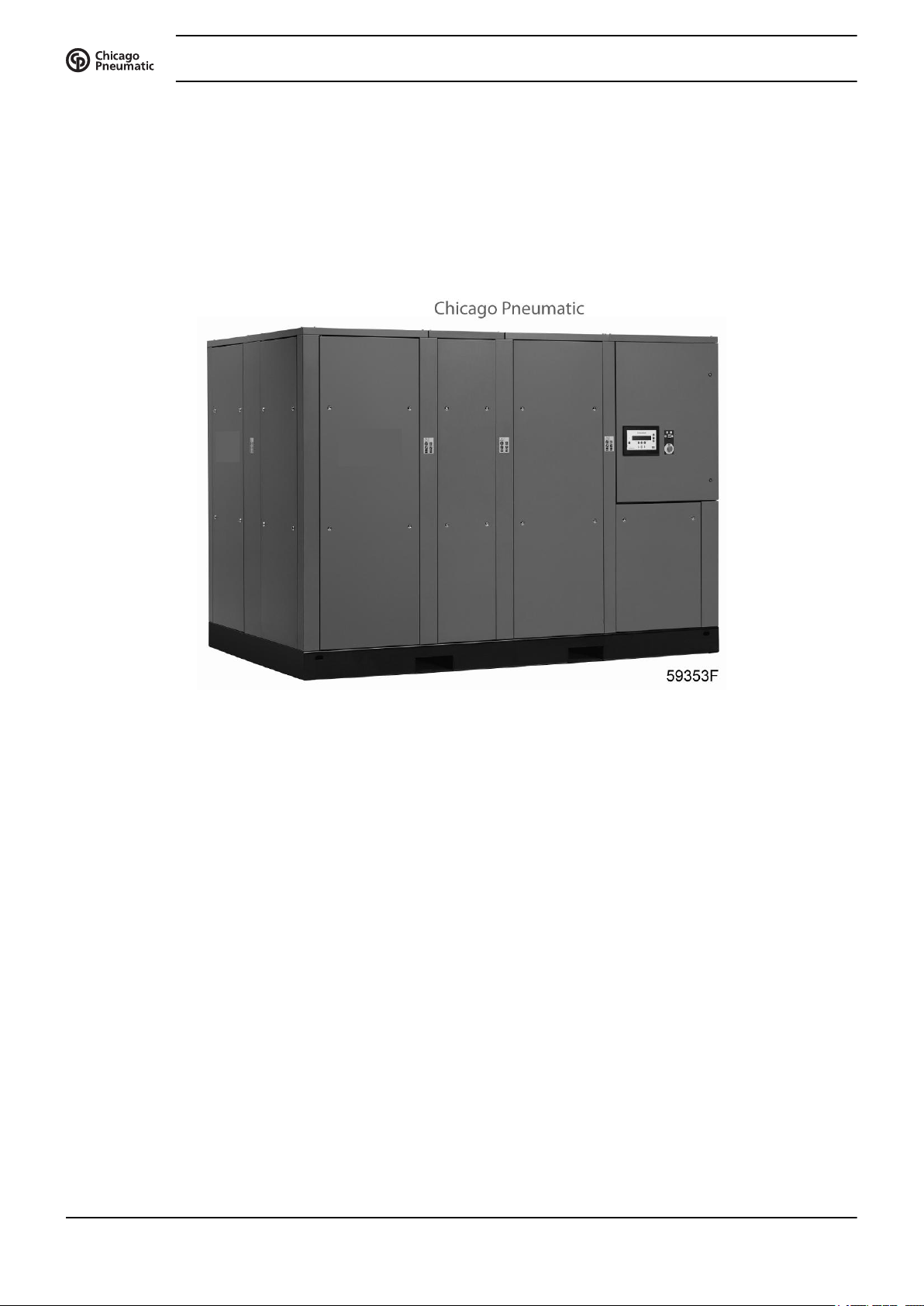
General
Instruction book
These units are single stage, oil-injected screw compressors, driven by an electric motor and enclosed in
sound-insulated bodywork.
The compressors can be either air-cooled or water-cooled.
The following features are available as an option:
Electronic drain
The electronic water drain assures proper draining of condensate and prevents water from entering the
compressed air net. For any malfunction of the draining process, the electronic water drain generates a warning
message on the display of the regulator.
Energy recovery
The compressor is provided with an energy recovery system to recover the major part of the compression heat
in the form of hot water without any influence on the compressor performance.
Modulating control
The modulating control system is designed to maintain a narrow net pressure band by throttling the air inlet,
thus reducing the air flow (50% - 100%).
General view
10 2920 1796 01
Instruction book
Phase Sequence Relay
The phase sequence relay prevents the drive motor from rotating in the wrong direction.
SPM monitoring
A number of vibration sensors are provided on the drive motor and compressor elements. The readings can
be called up on the display of the electronic regulator.
Full option main motor
Thermal protection is provided for the drive motor. Five sensors are installed in the motor, two to measure
the temperature of the bearings and three to measure the temperature of the windings. The readings can be
called up on the display of the electronic regulator. A message will appear on the display and the general
alarm LED will light up if one of the temperatures exceeds the shut-down warning setting.
RXD oil
RXD oil is a special, long-life lubricant for oil-injected screw compressors. It provides better cooling and
extends the oil change interval.
Foodgrade
Foodgrade oil is a unique high quality synthetic lubricant, specially created for oil-injected screw compressors
that provide air for the food industry. This lubricant keeps the compressor in excellent condition. Foodgrade
oil can be used for compressors operating at ambient temperatures between 0 ˚C (32 ˚F) and 40 ˚C (104 ˚F).
2.2 Cooling and condensate system
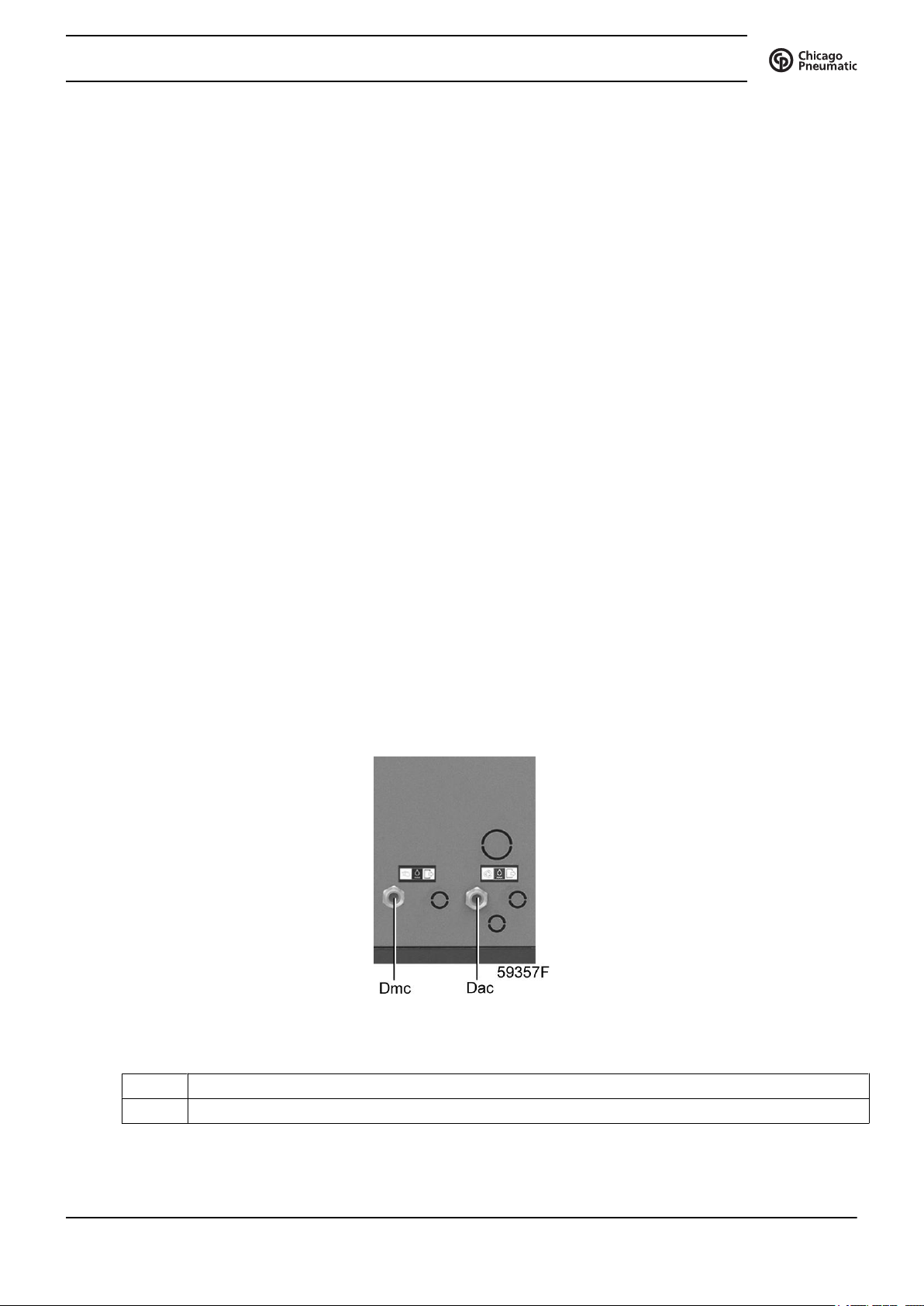
Condensate drain system
Condensate drains
Dac Automatic condensate drain, compressor
Dmc Manual condensate drain
2920 1796 01 11
Condensate traps are installed downstream of the air coolers to prevent condensate from entering the air outlet
pipe. The traps are provided with a float valve for automatically draining condensate and with a manual drain
valve.
Cooling system
On air-cooled compressors, the air and oil coolers are cooled by fans.
Water-cooled compressors are provided with a cooling water system, including combined oil and air coolers.
2.3 Regulating system
Flow diagrams
Instruction book
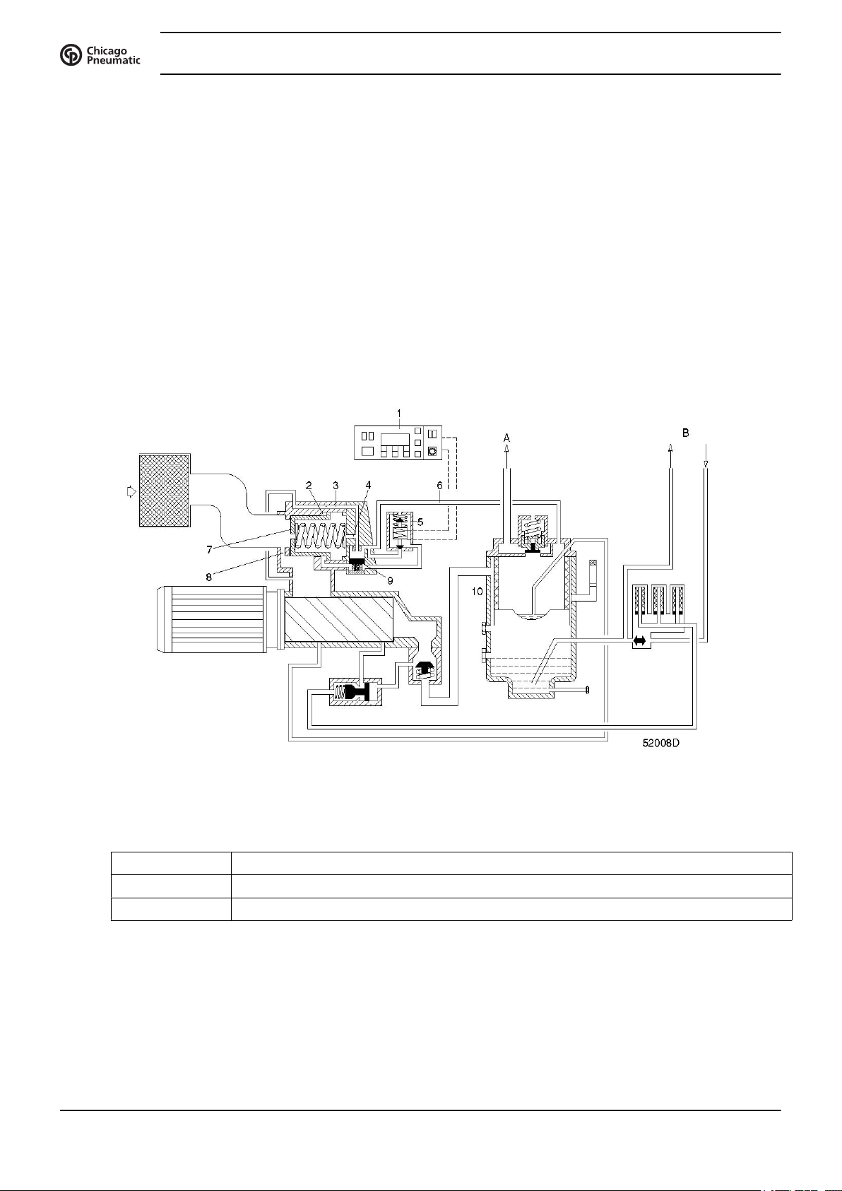
Flow diagram
Reference Designation
A To air cooler
B To/from oil cooler
Regulating system
The compressor is controlled by electronic regulator (1).
The regulator keeps the net pressure within programmable pressure limits by automatically loading and
unloading the compressor depending on the air consumption. It also protects the compressor and monitors
components subject to service.
12 2920 1796 01
Instruction book
Unloading
If the air consumption is less than the air delivery of the compressor, the net pressure increases. When the net
pressure reaches the upper limit of the working pressure (unloading pressure), solenoid valve (5) is deenergized by electronic regulator (1). The plunger of solenoid valve (5) moves downwards by spring force:
Phase Description
1 The plunger of solenoid valve (5) shuts off the supply of receiver pressure towards
2 Control pressure present in chamber (2) is vented to atmosphere through loading solenoid
3 Valve (9) is pushed downwards releasing receiver pressure through flexible (6) and
4 A small flow of air remains drawn in through hole (8) and channel (3), and is blown from
5 Air delivery is stopped (0%), the compressor runs unloaded.
Loading
chamber (2).
valve (5). Unloading valve (7) closes by spring force.
channels (3 and 4) towards the air inlet.
receiver (10) via flexible (6) to the air inlet.
When the net pressure decreases to the lower limit of the working pressure (loading pressure), solenoid valve
(5) is energized. The plunger of solenoid valve (5) moves upwards against spring force:
Phase
1 The plunger of solenoid valve (5) opens the supply of receiver pressure towards chamber
(2). Unloading valve (7) opens against spring force.
2 Receiver pressure also pushes valve (9) upwards, shutting off blow-off channels (3 and
4).
3 Air delivery is resumed (100%), the compressor runs loaded.
2920 1796 01 13

3 Electronic regulator
3.1 Electronic control system
Control panel
Instruction book
Introduction
The electronic controller has following functions:
• Controlling the compressor
• Protecting the compressor
• Monitoring components subject to service
• Automatic restart after voltage failure (made inactive)
Automatic control of the compressor operation
The regulator maintains the net pressure between programmable limits by automatically loading and unloading
the compressor. A number of programmable settings, e.g. the unloading and loading pressures, the minimum
stop time and the maximum number of motor starts are taken into account.
The regulator stops the compressor whenever possible to reduce the power consumption and restarts it
automatically when the net pressure decreases. In case the expected unloading period is too short, the
compressor is kept running to prevent too short standstill periods.
A number of time based automatic start/stop commands may be programmed. Take into
account that a start command will be executed (if programmed and activated), even after
manually stopping the compressor.
Protecting the compressor
Shut-down
14 2920 1796 01
Instruction book
Several sensors are provided on the compressor. If one of these measurements exceeds the programmed shutdown level, the compressor will be stopped. This will be indicated on display (1) and general alarm LED (4)
will blink.
Remedy the trouble and reset the message. See also the section Inputs menu.
Shut-down warning
A shut-down warning level is a programmable level below the shut-down level.
If one of the measurements exceeds the programmed shut-down warning level, a message will appear on
display (1) and general alarm LED (4) will light up, to warn the operator that the shut-down warning level is
exceeded.
The message disappears as soon as the warning condition disappears.
Service warning
Before remedying, consult the applicable safety precautions.
A number of service operations are grouped (called Service Plans). Each Service Plan has a programmed time
interval. If a time interval is exceeded, a message will appear on display (1) to warn the operator to carry out
the service actions belonging to that Service Plan.
Automatic restart after voltage failure
The regulator has a built-in function to automatically restart the compressor if the voltage is restored after
voltage failure. For compressors leaving the factory, this function is made inactive. If desired, the function
can be activated. Consult your Customer Centre.
If activated and provided the regulator was in the automatic operation mode, the
compressor will automatically restart if the supply voltage to the module is restored.
2920 1796 01 15
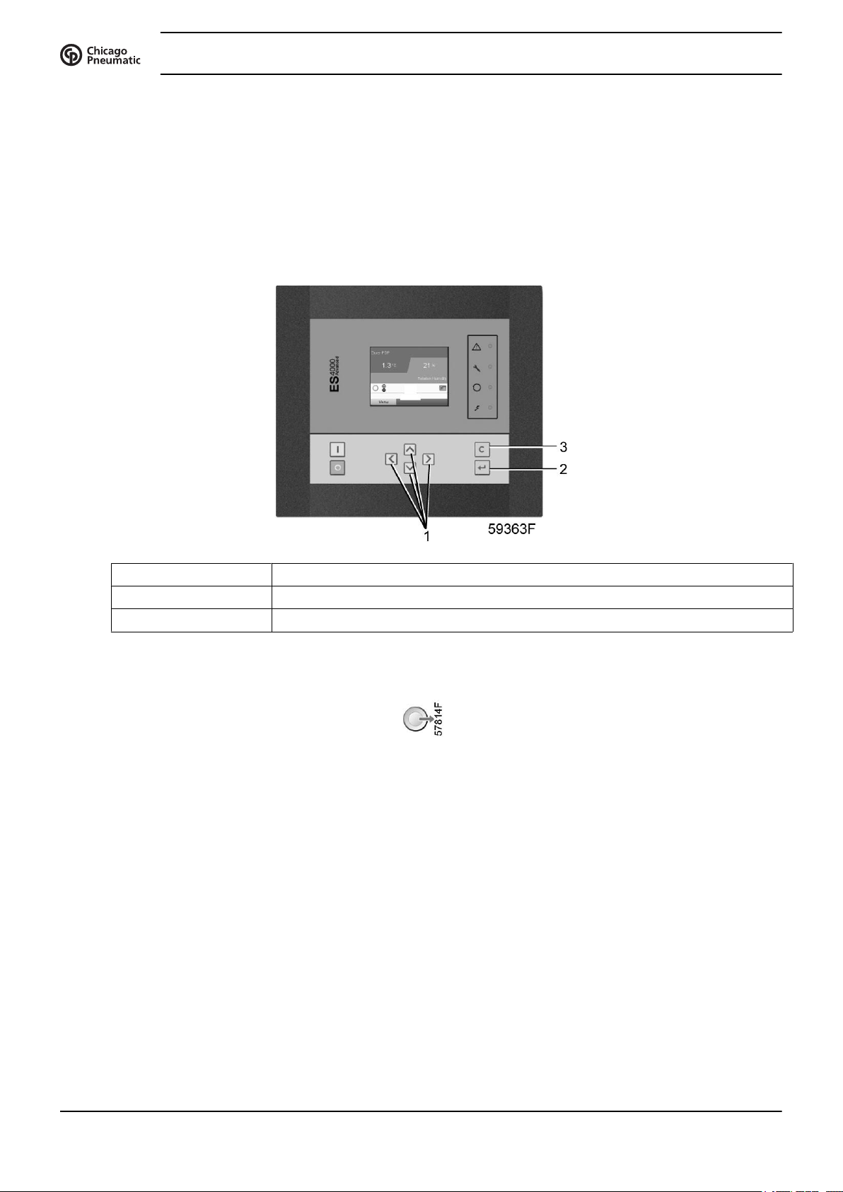
3.2 Control panel
Electronic regulator
Instruction book
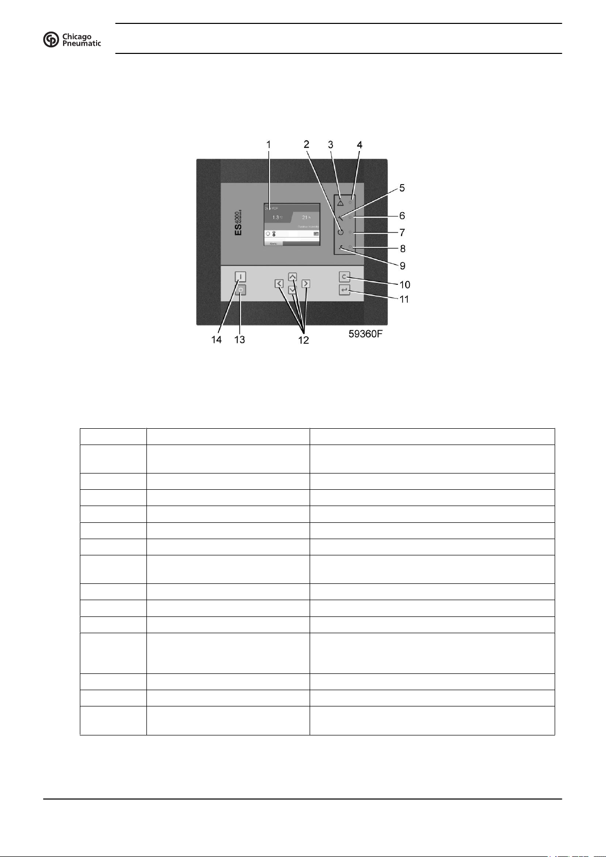
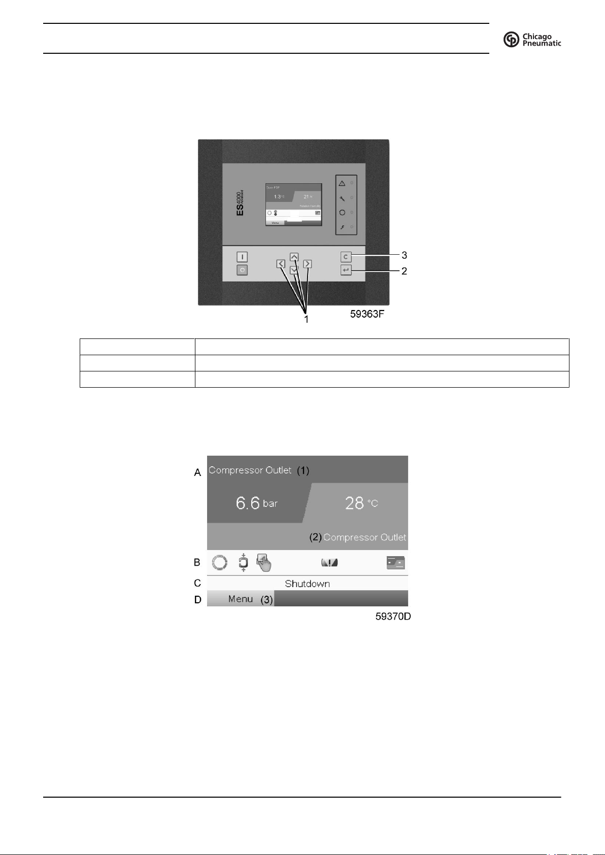
Parts and functions
Reference Designation Function
1 Display Shows the compressor operating condition and a
2 Pictograph Automatic operation
3 Pictograph General alarm
4 General alarm LED Flashes if a shut-down warning condition exists.
5 Pictograph Service
6 Service LED Lights up if service is needed
7 Automatic operation LED Indicates that the regulator is automatically controlling
8 Voltage on LED Indicates that the voltage is switched on.
9 Pictograph Voltage on
10 Escape key To go to previous screen or to end the current action
11 Enter key Key to select the parameter indicated by the horizontal
12 Scroll keys Keys to scroll through the menu.
13 Stop button Button to stop the compressor. LED (7) goes out.
14 Start button Button to start the compressor. LED (7) lights up
Control panel
number of icons to navigate through the menu.
the compressor.
arrow. Only the parameters followed by an arrow
pointing to the right can be modified.
indicating that the electronic regulator is operative.
16 2920 1796 01
Instruction book
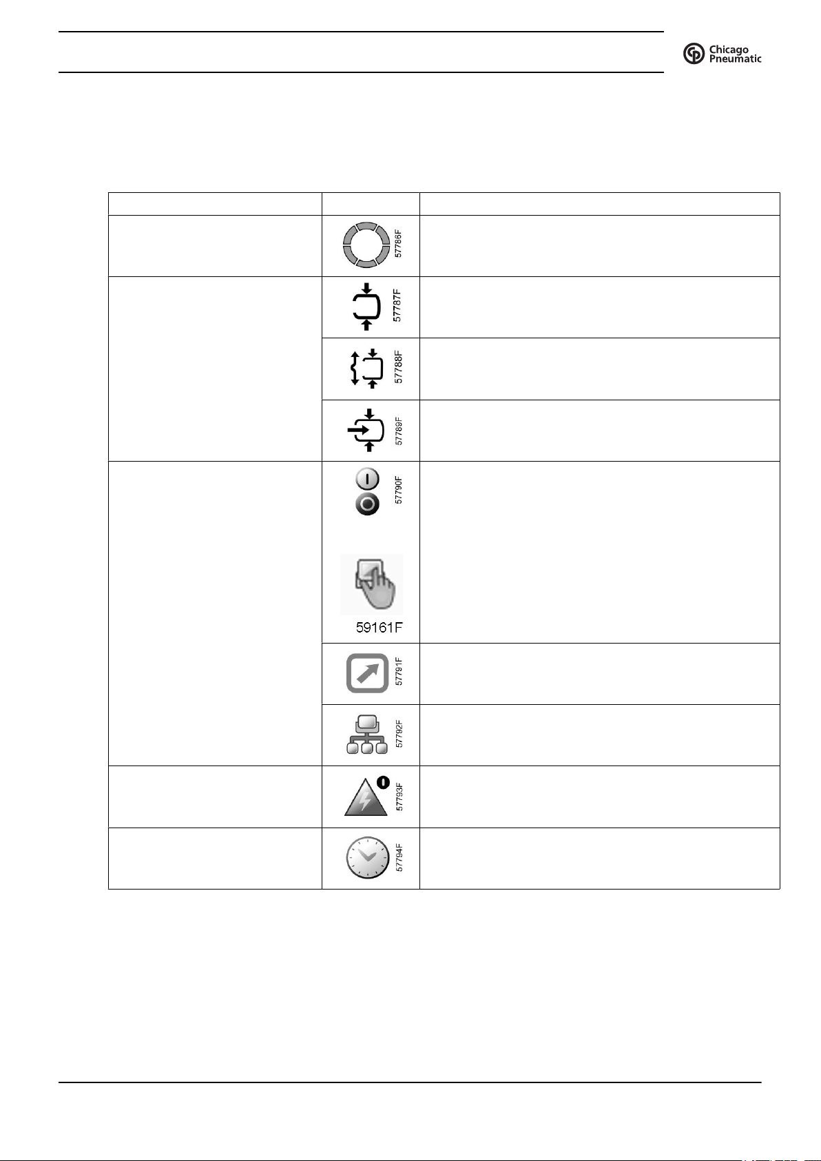
3.3 Icons used
Status icons
Name Icon Description
Stopped / Running When the compressor is stopped, the icon stands still.
Compressor status Motor stopped
When the compressor is running, the icon is rotating.
Running unloaded
Running loaded
Machine control mode
or
Automatic restart after voltage
failure
Week timer Week timer is active
Local start / stop
Remote start / stop
Network control
Automatic restart after voltage failure is active
2920 1796 01 17
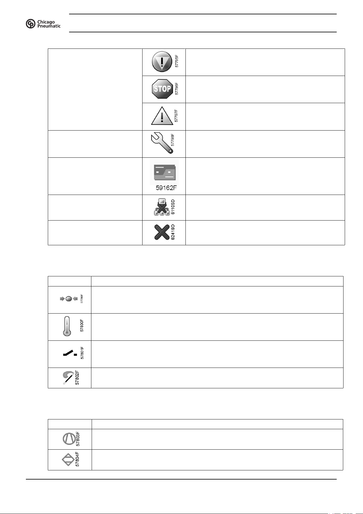
Active protection functions Emergency stop
Shutdown
Warning
Service Service required
Main screen display Value lines display icon
General icons No communication / network problem
Instruction book
Not valid
Input icons
Icon Description
Pressure
Temperature
Digital input
Special protection
System icons
Icon Description
Compressor element (LP, HP, ...)
Dryer
18 2920 1796 01
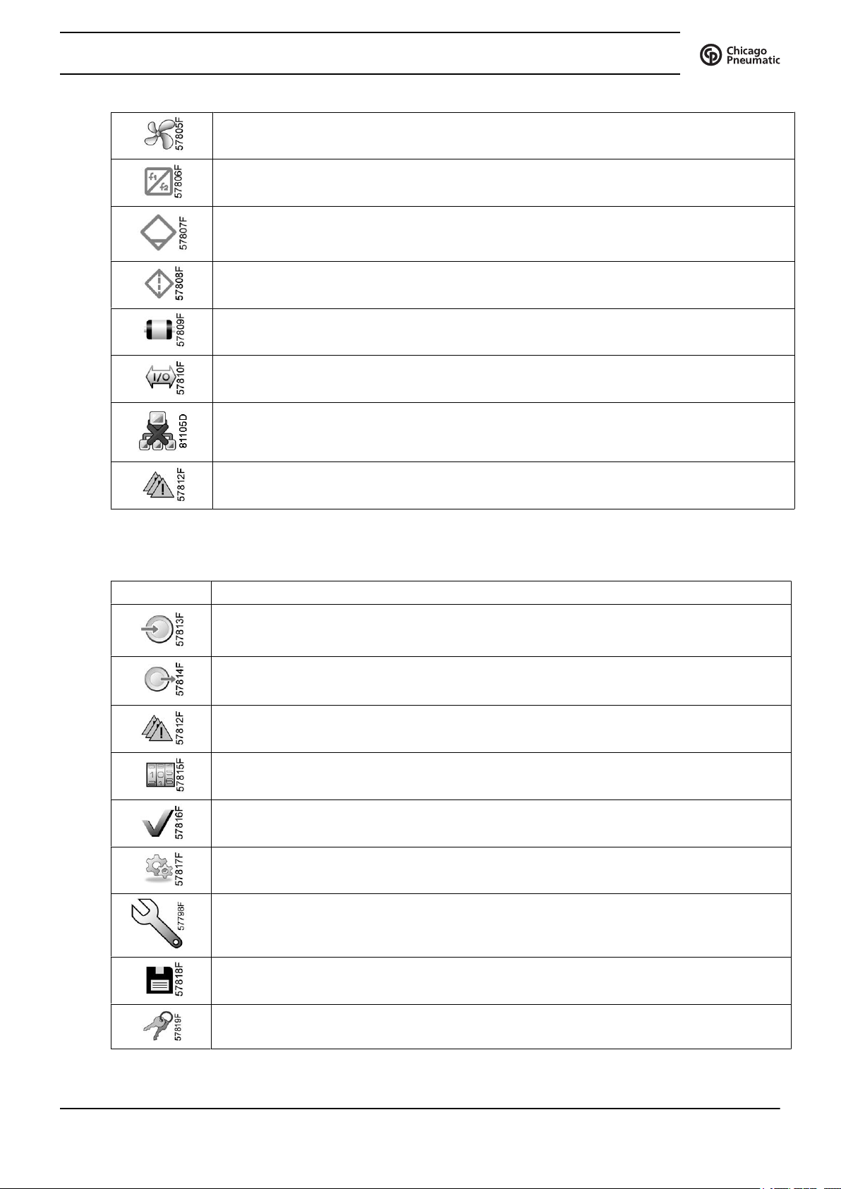
Instruction book
Fan
Frequency converter
Drain
Filter
Motor
Failure expansion module
Network problem
Menu icons
Icon Description
General alarm
Inputs
Outputs
Alarms (Warnings, shutdowns)
Counters
Test
Settings
Service
Event history (saved data)
Access key / User password
2920 1796 01 19
Navigation arrows
Icon Description
Instruction book
Network
Setpoint
Info
Up
Down
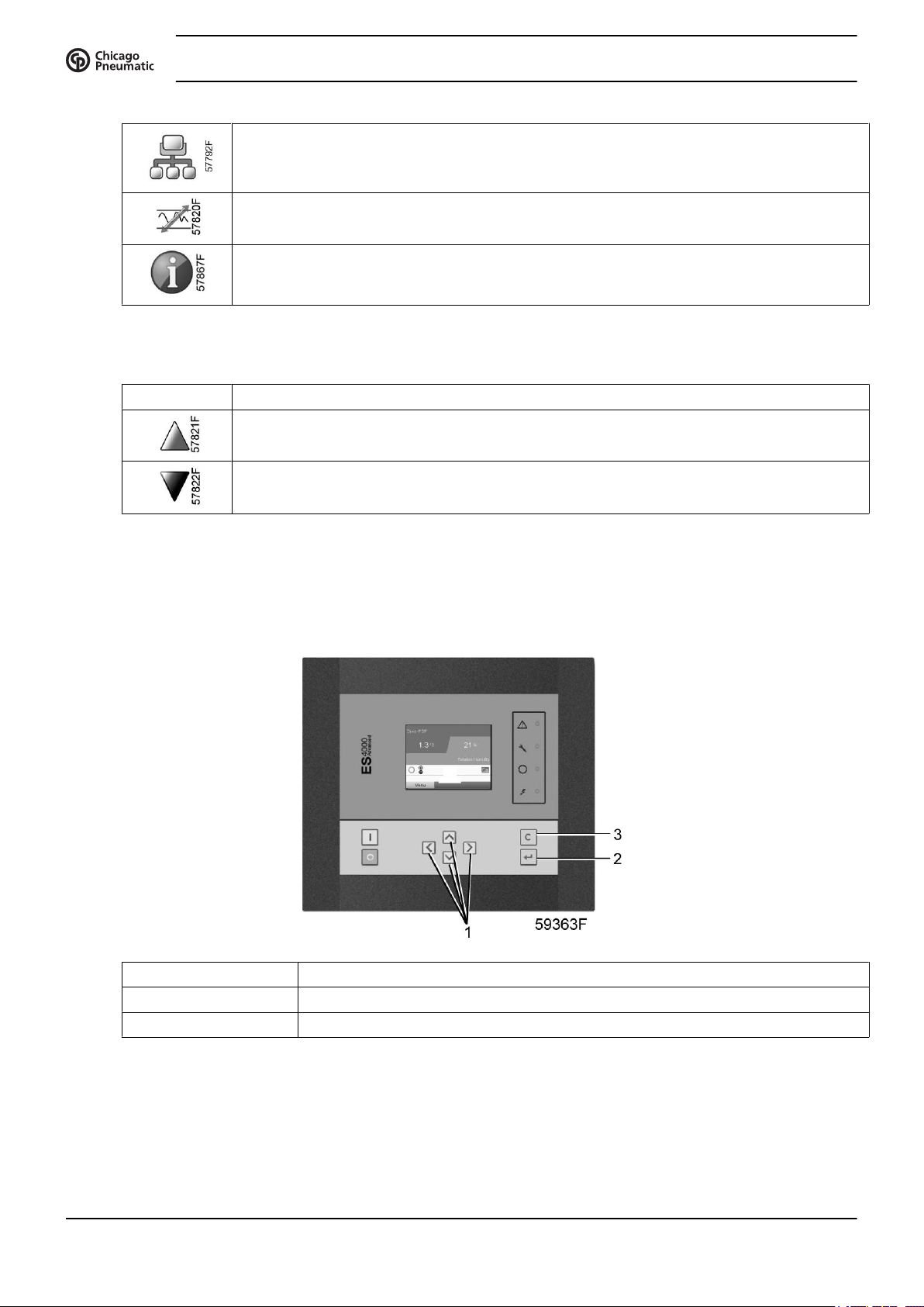
3.4 Main screen
Control panel
(1) Scroll keys
(2) Enter key
(3) Escape key
Function
The Main screen is the screen that is shown automatically when the voltage is switched on and one of the
keys is pushed. It is switched off automatically after a few minutes when no keys are pushed.
Typically, 2 different main screen views can be chosen:
20 2920 1796 01

Instruction book
1. Two value lines
2. Four value lines
Two and four value lines screens
This type of Main screen shows the value of 2 or 4 parameters (see section Inputs menu).
Typical Main screen (2 value lines)
Text on figures
(1) Compressor Outlet
(2) Compressor Outlet
(3) Menu
Typical Main screen (4 value lines)
Text on figures
(1) Compressor Outlet
(2) Loaded Hours
(3) Standby,... (text varies upon the compressor's actual condition)
(4) Menu
2920 1796 01 21
Instruction book
(5) Running hours
(6) Compressor outlet
• Section A shows information regarding the compressor operation (e.g. the outlet pressure or the
temperature at the compressor outlet).
• Section B shows Status icons. Following icon types are shown in this field:
• Fixed icons
These icons are always shown in the main screen and cannot be selected by the cursor (e.g. Compressor
stopped or running, Compressor status (running, running unloaded or motor stopped)).
• Optional icons
These icons are only shown if their corresponding function is activated (e.g. week timer, automatic
restart after voltage failure , etc.)
• Pop up icons
These icons pop up if an abnormal condition occurs (warnings, shutdowns, service,...)
To call up more information about the icons shown, select the icon concerned using the scroll keys and
press the enter key.
• Section C is called the Status bar
This bar shows the text that corresponds to the selected icon.
• Section D shows the Action buttons. These buttons are used:
• To call up or program settings
• To reset a motor overload, service message or emergency stop
• To have access to all data collected by the regulator
The function of the buttons depends on the displayed menu. The most common functions are:
Designation Function
Menu To go to the menu
Modify To modify programmable settings
Reset To reset a timer or message
To activate an action button, highlight the button by using the Scroll keys and press the Enter key.
To go back to the previous menu, press the Escape key.
Selection of a main screen view
To change between the screen layouts, select the far right icon in the control icons line (see value lines display
icon in section Icons used) and press the Enter key.
Select the layout required and press the Enter key.
22 2920 1796 01
Instruction book
3.5 Calling up menus
Control panel
(1) Scroll keys
(2) Enter key
(3) Escape key
Description
When the voltage is switched on, the main screen is shown automatically (see section Main screen):
Typical Main screen (2 value lines)
• To go to the Menu screen, highlight the Menu button (3), using the Scroll keys.
• Press the Enter key to select the menu. Following screen appears:
2920 1796 01 23
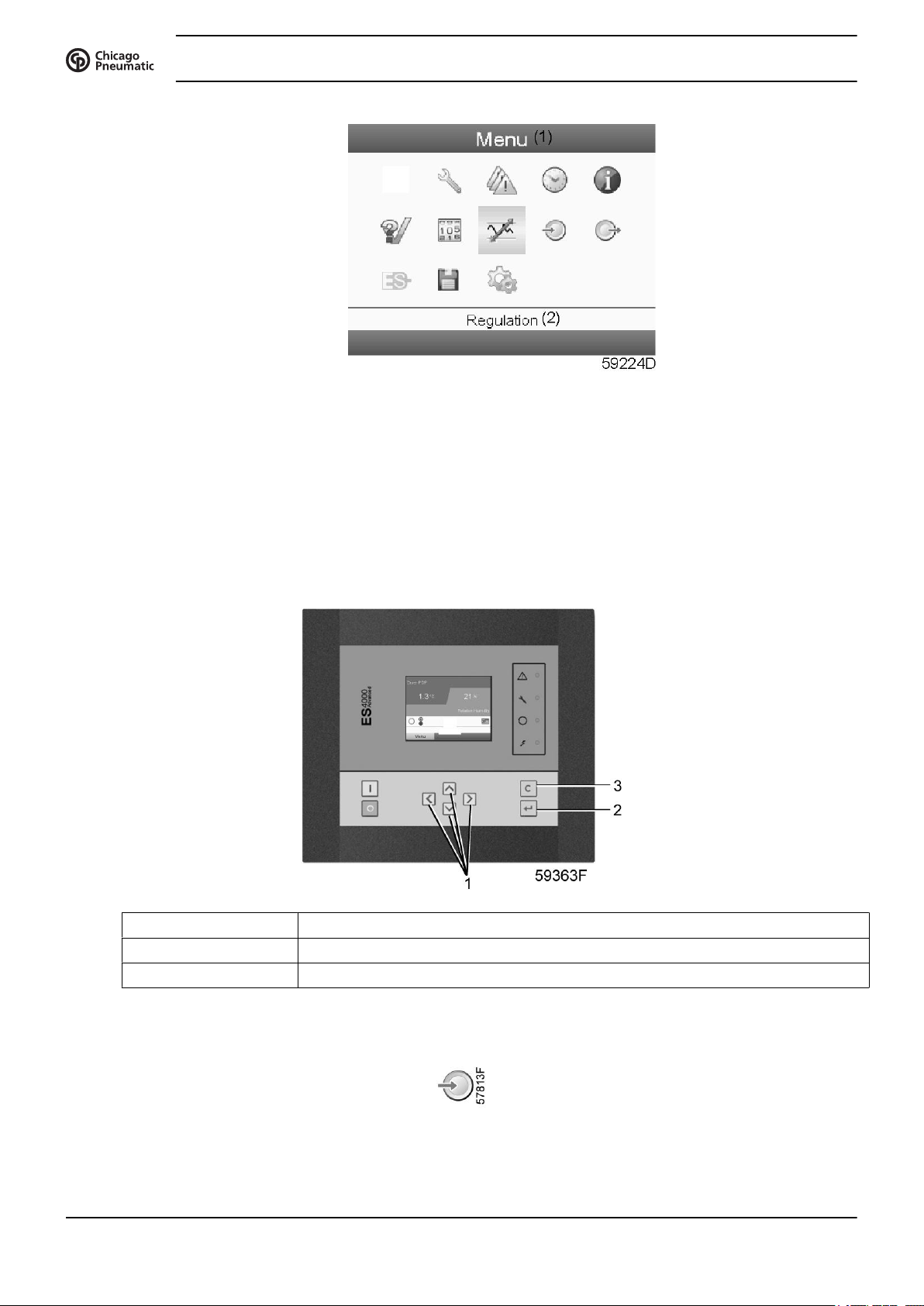
Instruction book
• The screen shows a number of icons. Each icon indicates a menu item. By default, the Pressure Settings
(Regulation) icon is selected. The status bar shows the name of the menu that corresponds with the selected
icon.
• Use the Scroll keys to select an icon.
• Press the Escape key to return to the Main screen.
3.6 Inputs menu
Control panel
(1) Scroll keys
(2) Enter key
(3) Escape key
Menu icon, Inputs
24 2920 1796 01
Instruction book
Function
• To display the actual value of the measured data (analog inputs) and the status of the digital inputs (e.g.
emergency stop contact, motor overload relay, etc.).
• To select the digital input to be shown on the chart in the main screen.
Procedure
Starting from the main screen (see section Main screen),
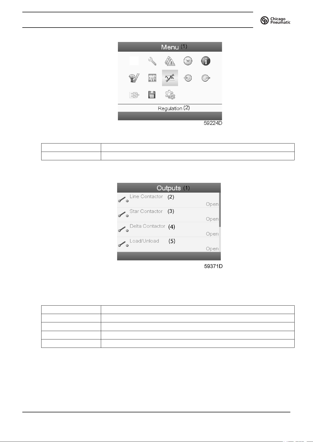
• Move the cursor to the Menu action button and press the Enter key. Following screen appears:
Text on image
(1) Menu
(2) Regulation
• Using the Scroll keys, move the cursor to the Inputs icon (see above, section Menu icon).
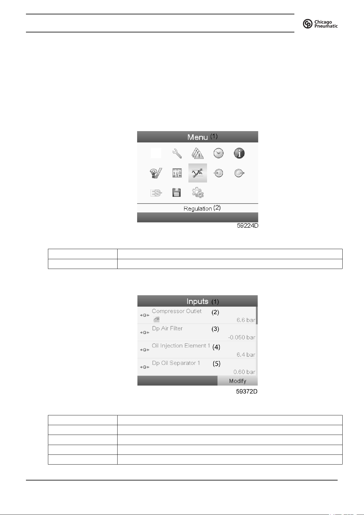
• Press the Enter key. A screen similar to the one below appears:
Text on image
(1) Inputs
(2) Compressor outlet
(3) Dp air filter
(4) Oil injection element
(5) Dp oil separator
2920 1796 01 25
• The screen shows a list of all inputs with their corresponding icons and readings.
• If an input is in warning or shutdown, the original icon is replaced by the warning or shutdown icon
respectively (i.c. the Stop icon and the Warning icon in the screen shown above).
3.7 Outputs menu
Control panel
Instruction book
(1) Scroll keys
(2) Enter key
(3) Escape key
Menu icon, Outputs
Function
To call up information regarding the actual status of some outputs such as the condition of the Fan overload
contact (on air-cooled compressors), the Emergency stop contact, etc.
Procedure
Starting from the Main screen (see section Main screen),
• Move the cursor to the Menu action button and press the Enter key. Following screen appears:
26 2920 1796 01
Instruction book
Text on figure
(1) Menu
(2) Regulation
• Move the cursor to the Outputs icon (see above, section Menu icon, using the Scroll keys.
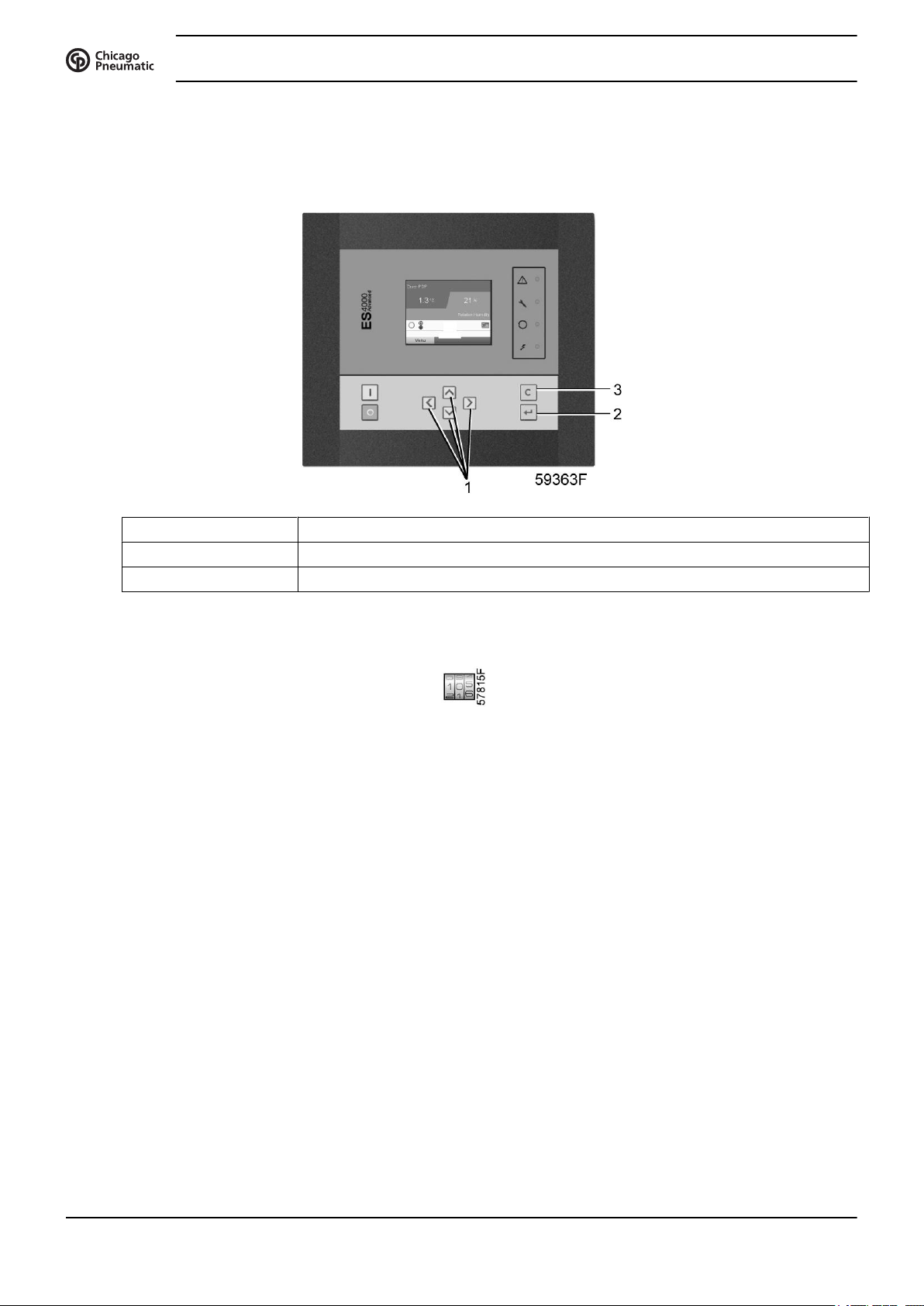
• Press the Enter key. A screen similar to the one below appears:
Outputs screen (typical)
Text on figure
(1) Outputs
(2) Line contactor
(3) Star contactor
(4) Delta contactor
(5) Load/Unload
• The screen shows a list of all outputs with their corresponding icons and readings.
If an output is in warning or shutdown, the original icon is replaced by the warning or shutdown icon
respectively.
2920 1796 01 27
3.8 Counters
Control panel
Instruction book
(1) Scroll keys
(2) Enter key
(3) Escape key
Menu icon, Counters
Function
To call up:
• The running hours
• The loaded hours
• The number of motor starts
• The number of hours that the regulator has been powered
• The number of load cycles
Procedure
Starting from the Main screen (see section Main screen),
• Move the cursor to the Menu action button and press the Enter key. Following screen appears:
28 2920 1796 01
 Loading...