

Chicago Pneumatic CPC 40 G, CPC 60 G, CPD 75 G, CPD 100 G, CPE 120 Instruction Book
...
Oil-injected rotary screw compressors
People. Passion. Performance.
CPC 40 G, CPC 50 G, CPC 60 G, CPD 75 G, CPD 100 G, CPE 100,
CPE 120, CPE 150
Instruction book


Oil-injected rotary screw compressors
CPC 40 G, CPC 50 G, CPC 60 G, CPD 75 G, CPD 100 G,
CPE 100, CPE 120, CPE 150
From following serial No. onwards: API172431
Instruction book
Original instructions
Copyright notice
Any unauthorized use or copying of the contents or any part thereof is prohibited.
This applies in particular to trademarks, model denominations, part numbers and
drawings.
This instruction book is valid for CE as well as non-CE labelled machines. It meets the
requirements for instructions specified by the applicable European directives as
identified in the Declaration of Conformity.
2014 - 12
No. 2920 7101 41
www.cp.com

Instruction book
Table of contents
1 Safety precautions..........................................................................................................6
1.1 SAFETY ICONS................................................................................................................................... 6
1.2 GENERAL SAFETY PRECAUTIONS............................................................................................................6
1.3 SAFETY PRECAUTIONS DURING INSTALLATION...........................................................................................7
1.4 SAFETY PRECAUTIONS DURING OPERATION.............................................................................................. 8
1.5 SAFETY PRECAUTIONS DURING MAINTENANCE OR REPAIR........................................................................... 9
2 General description......................................................................................................11
2.1 INTRODUCTION.................................................................................................................................11
2.2 AIR AND OIL CIRCUIT......................................................................................................................... 13
2.3 REGULATING SYSTEM........................................................................................................................ 16
2.4 ELECTRICAL SYSTEM.........................................................................................................................17
3 Controller.......................................................................................................................19
3.1 CONTROLLER...................................................................................................................................19
3.2 CONTROL PANEL.............................................................................................................................. 20
3.3 ICONS USED ON THE DISPLAY..............................................................................................................21
3.4 MAIN SCREEN..................................................................................................................................23
3.5 SHUT-DOWN WARNING.......................................................................................................................24
3.6 SHUT-DOWN....................................................................................................................................25
3.7 SERVICE WARNING............................................................................................................................26
3.8 SCROLLING THROUGH ALL SCREENS.....................................................................................................27
3.9 CALLING UP OUTLET AND DEWPOINT TEMPERATURES...............................................................................31
3.10 CALLING UP RUNNING HOURS..............................................................................................................32
3.11 CALLING UP MOTOR STARTS............................................................................................................... 32
3.12 CALLING UP MODULE HOURS...............................................................................................................32
3.13 CALLING UP LOADING HOURS.............................................................................................................. 33
3.14 CALLING UP LOAD RELAY................................................................................................................... 33
2 2920 7101 41

Instruction book
3.15 CALLING UP/RESETTING THE SERVICE TIMER ......................................................................................... 33
3.16 SELECTION BETWEEN LOCAL, REMOTE OR LAN CONTROL........................................................................34
3.17 CALLING UP/MODIFYING CAN ADDRESS CONTROL.................................................................................. 35
3.18 CALLING UP/MODIFYING IP, GATEWAY AND SUBNETMASK........................................................................36
3.19 CALLING UP/MODIFYING PRESSURE BAND SETTINGS.................................................................................38
3.20 MODIFYING THE PRESSURE BAND SELECTION......................................................................................... 39
3.21 CALLING UP/MODIFYING SERVICE TIMER SETTINGS...................................................................................39
3.22 CALLING UP/MODIFYING THE UNIT OF TEMPERATURE................................................................................40
3.23 CALLING UP/MODIFYING UNIT OF PRESSURE...........................................................................................40
3.24 ACTIVATING AUTOMATIC RESTART AFTER VOLTAGE FAILURE...................................................................... 40
3.25 SELECTION BETWEEN Y-D OR DOL STARTING......................................................................................41
3.26 CALLING UP MODIFYING LOAD DELAY TIME............................................................................................. 41
3.27 CALLING UP MODIFYING MINIMUM STOP TIME..........................................................................................41
3.28 ACTIVATING PASSWORD PROTECTION................................................................................................... 42
3.29 ACTIVATE LOAD/UNLOAD REMOTE PRESSURE SENSING............................................................................. 42
3.30 CALLING UP/MODIFYING PROTECTION SETTINGS...................................................................................... 43
3.31 TEST SCREENS................................................................................................................................ 44
3.32 PROGRAMMABLE SETTINGS.................................................................................................................45
4 Installation.....................................................................................................................48
4.1 DIMENSION DRAWINGS.......................................................................................................................48
4.2 INSTALLATION PROPOSAL................................................................................................................... 49
4.3 PICTOGRAPHS................................................................................................................................. 52
5 Operating instructions................................................................................................. 54
5.1 INITIAL START-UP..............................................................................................................................54
5.2 BEFORE STARTING............................................................................................................................57
5.3 STARTING ...................................................................................................................................... 58
5.4 DURING OPERATION..........................................................................................................................59
5.5 AUTOMATIC RESTARTING....................................................................................................................60
2920 7101 41 3

Instruction book
5.6 STOPPING ......................................................................................................................................60
5.7 TAKING OUT OF OPERATION................................................................................................................61
6 Maintenance..................................................................................................................62
6.1 PREVENTIVE MAINTENANCE SCHEDULE..................................................................................................62
6.2 STORAGE AFTER INSTALLATION........................................................................................................... 64
6.3 SERVICE KITS.................................................................................................................................. 64
6.4 DISPOSAL OF USED MATERIAL............................................................................................................. 65
7 Adjustments and servicing procedures..................................................................... 66
7.1 AIR FILTER......................................................................................................................................66
7.2 OIL AND OIL FILTER CHANGE...............................................................................................................67
7.3 OIL SEPARATOR CHANGE................................................................................................................... 68
7.4 COOLERS....................................................................................................................................... 69
7.5 FILTERING PANEL............................................................................................................................. 70
7.6 SAFETY VALVES............................................................................................................................... 71
7.7 DRYER MAINTENANCE INSTRUCTIONS....................................................................................................71
8 Problem solving............................................................................................................73
9 Technical data...............................................................................................................77
9.1 ELECTRIC CABLE SIZE AND FUSES........................................................................................................77
9.2 REFERENCE CONDITIONS AND LIMITATIONS............................................................................................ 92
9.3 COMPRESSOR DATA..........................................................................................................................93
10 Options.......................................................................................................................... 95
10.1 ENERGY RECOVERY.......................................................................................................................... 95
10.2 ECO6I........................................................................................................................................ 103
10.3 AUTOMATIC DRAIN.......................................................................................................................... 114
10.4 HEAVY DUTY FILTER........................................................................................................................115
10.5 PRE-FILTRATION PANELS..................................................................................................................115
4 2920 7101 41

Instruction book
10.6 ROTATION DIRECTION INDICATOR - PHASE CONTROLLER........................................................................ 118
10.7 SPECIAL OILS................................................................................................................................ 118
10.8 CENTRIFUGAL WATER SEPARATION.....................................................................................................118
10.9 GRAPHIC CONTROLLER................................................................................................................... 119
10.10 TROPICAL THERMOSTATIC VALVE....................................................................................................... 120
11 Guidelines for inspection...........................................................................................121
12 Pressure equipment directives................................................................................. 122
13 Declaration of conformity.......................................................................................... 124
2920 7101 41 5
1 Safety precautions
1.1 Safety icons
Explanation
Danger for life
Warning
Important note
Instruction book
1.2 General safety precautions
1. The operator must employ safe working practices and observe all related work safety requirements
and regulations.
2. If any of the following statements does not comply with the applicable legislation, the stricter of the
two shall apply.
3. Installation, operation, maintenance and repair work must only be performed by authorized, trained,
specialized personnel. The personnel should apply safe working practices by use of personal
protection equipment, appropriate tools and defined procedures.
4. The compressor is not considered capable of producing air of breathing quality. For air of breathing
quality, the compressed air must be adequately purified according to the applicable legislation and
standards.
5. Before any maintenance, repair work, adjustment or any other non-routine checks:
• Stop the compressor
• Press the emergency stop button
• Switch off the voltage
• Depressurize the compressor
• Lock Out - Tag Out (LOTO):
• Open the power isolating switch and lock it with a personal lock
• Tag the power isolating switch with the name of the service technician.
• On units powered by a frequency converter, wait 10 minutes before starting any electrical repair.
• Never rely on indicator lamps or electrical door locks before maintenance work, always
disconnect and check with measuring device.
If the machine is equipped with an automatic restart after voltage failure function and if
this function is active, be aware that the machine will restart automatically when the
power is restored if it was running when the power was interrupted!
6. Never play with compressed air. Do not apply the air to your skin or direct an air stream at people.
Never use the air to clean dirt from your clothes. When using the air to clean equipment, do so with
extreme caution and wear eye protection.
7. The owner is responsible for maintaining the unit in safe operating condition. Parts and accessories
shall be replaced if unsuitable for safe operation.
8. It is prohibited to walk or stand on the unit or on its components.
6 2920 7101 41

Instruction book
1.3 Safety precautions during installation
All responsibility for any damage or injury resulting from neglecting these precautions, or
non observance of the normal caution and care required for installation, operation,
maintenance and repair, even if not expressly stated, will be disclaimed by the
manufacturer.
Precautions during installation
1. The machine must only be lifted using suitable equipment in accordance with the applicable safety
regulations. Loose or pivoting parts must be securely fastened before lifting. It is strictly forbidden to
dwell or stay in the risk zone under a lifted load. Lifting acceleration and deceleration must be kept
within safe limits. Wear a safety helmet when working in the area of overhead or lifting equipment.
2. The unit is designed for indoor use. If the unit is installed outdoors, special precautions must be taken;
consult your supplier.
3. In case the device is a compressor, place the machine where the ambient air is as cool and clean as
possible. If necessary, install a suction duct. Never obstruct the air inlet. Care must be taken to
minimize the entry of moisture at the inlet air.
4. Any blanking flanges, plugs, caps and desiccant bags must be removed before connecting the pipes.
5. Air hoses must be of correct size and suitable for the working pressure. Never use frayed, damaged or
worn hoses. Distribution pipes and connections must be of the correct size and suitable for the
working pressure.
6. In case the device is a compressor, the aspirated air must be free of flammable fumes, vapors and
particles, e.g. paint solvents, that can lead to internal fire or explosion.
7. In case the device is a compressor, arrange the air intake so that loose clothing worn by people cannot
be drawn in.
8. Ensure that the discharge pipe from the compressor to the aftercooler or air net is free to expand under
heat and that it is not in contact with or close to flammable materials.
9. No external force may be exerted on the air outlet valve; the connected pipe must be free of strain.
10. If remote control is installed, the machine must bear a clear sign stating: DANGER: This machine is
remotely controlled and may start without warning.
The operator has to make sure that the machine is stopped and depressurized and that the electrical
isolating switch is open, locked and labelled with a temporary warning before any maintenance or
repair. As a further safeguard, persons switching on or off remotely controlled machines shall take
adequate precautions to ensure that there is no one checking or working on the machine. To this end,
a suitable notice shall be affixed to the start equipment.
11. Air-cooled machines must be installed in such a way that an adequate flow of cooling air is available
and that the exhausted air does not recirculate to the compressor air inlet or cooling air inlet.
12. The electrical connections must correspond to the applicable codes. The machines must be earthed
and protected against short circuits by fuses in all phases. A lockable power isolating switch must be
installed near the compressor.
13. On machines with automatic start/stop system or if the automatic restart function after voltage failure
is activated, a sign stating "This machine may start without warning" must be affixed near the
instrument panel.
14. In multiple compressor systems, manual valves must be installed to isolate each compressor. Nonreturn valves (check valves) must not be relied upon for isolating pressure systems.
15. Never remove or tamper with the safety devices, guards or insulation fitted on the machine. Every
pressure vessel or auxiliary installed outside the machine to contain air above atmospheric pressure
must be protected by a pressure relieving device or devices as required.
2920 7101 41 7
Instruction book
16. Piping or other parts with a temperature in excess of 70˚C (158˚F) and which may be accidentally
touched by personnel in normal operation must be guarded or insulated. Other high temperature
piping must be clearly marked.
17. For water-cooled machines, the cooling water system installed outside the machine has to be
protected by a safety device with set pressure according to the maximum cooling water inlet pressure.
18. If the ground is not level or can be subject to variable inclination, consult the manufacturer.
19. If the device is a dryer and no free extinguishing system is present in the air net close to the dryer,
safety valves must be installed in the vessels of the dryer.
Also consult following safety precautions: Safety precautions during operation and
Safety precautions during maintenance.
These precautions apply to machinery processing or consuming air or inert gas.
Processing of any other gas requires additional safety precautions typical to the
application which are not included herein.
Some precautions are general and cover several machine types and equipment; hence
some statements may not apply to your machine.
1.4 Safety precautions during operation
All responsibility for any damage or injury resulting from neglecting these precautions, or
non observance of the normal caution and care required for installation, operation,
maintenance and repair, even if not expressly stated, will be disclaimed by the
manufacturer.
Precautions during operation
1. Never touch any piping or components of the machine during operation.
2. Use only the correct type and size of hose end fittings and connections. When blowing through a hose
or air line, ensure that the open end is held securely. A free end will whip and may cause injury. Make
sure that a hose is fully depressurized before disconnecting it.
3. Persons switching on remotely controlled machines shall take adequate precautions to ensure that
there is no one checking or working on the machine. To this end, a suitable notice shall be affixed to
the remote start equipment.
4. Never operate the machine when there is a possibility of taking in flammable or toxic fumes, vapors
or particles.
5. Never operate the machine below or in excess of its limit ratings.
6. Keep all bodywork doors shut during operation. The doors may be opened for short periods only, e.g.
to carry out routine checks. Wear ear protectors when opening a door.
On machines without bodywork, wear ear protection in the vicinity of the machine.
7. People staying in environments or rooms where the sound pressure level reaches or exceeds 80 dB(A)
shall wear ear protectors.
8. Periodically check that:
• All guards are in place and securely fastened
• All hoses and/or pipes inside the machine are in good condition, secure and not rubbing
• No leaks occur
• All fasteners are tight
• All electrical leads are secure and in good order
• Safety valves and other pressure relief devices are not obstructed by dirt or paint
• Air outlet valve and air net, i.e. pipes, couplings, manifolds, valves, hoses, etc. are in good
repair, free of wear or abuse
8 2920 7101 41
Instruction book
9. If warm cooling air from compressors is used in air heating systems, e.g. to warm up a workroom,
take precautions against air pollution and possible contamination of the breathing air.
10. On water-cooled compressors using open circuit cooling towers, protective measures must be taken to
avoid the growth of harmful bacteria such as Legionella pneumophila bacteria.
11. Do not remove any of, or tamper with, the sound-damping material.
12. Never remove or tamper with the safety devices, guards or insulations fitted on the machine. Every
pressure vessel or auxiliary installed outside the machine to contain air above atmospheric pressure
shall be protected by a pressure relieving device or devices as required.
13. Yearly inspect the air receiver. Minimum wall thickness as specified in the instruction book must be
respected. Local regulations remain applicable if they are more strict.
• Air cooling filters of the electrical cabinet are not clogged
Also consult following safety precautions: Safety precautions during installation and
Safety precautions during maintenance.
These precautions apply to machinery processing or consuming air or inert gas.
Processing of any other gas requires additional safety precautions typical to the
application which are not included herein.
Some precautions are general and cover several machine types and equipment; hence
some statements may not apply to your machine.
1.5 Safety precautions during maintenance or repair
All responsibility for any damage or injury resulting from neglecting these precautions, or
non observance of the normal caution and care required for installation, operation,
maintenance and repair, even if not expressly stated, will be disclaimed by the
manufacturer.
Precautions during maintenance or repair
1. Always use the correct safety equipment (such as safety glasses, gloves, safety shoes, etc.).
2. Use only the correct tools for maintenance and repair work.
3. Use only genuine spare parts for maintenance or repair. The manufacturer will disclaim all damage or
injuries caused by the use of non-genuine spare parts.
4. All maintenance work shall only be undertaken when the machine has cooled down.
5. A warning sign bearing a legend such as "Work in progress; do not start" shall be attached to the
starting equipment.
6. Persons switching on remotely controlled machines shall take adequate precautions to ensure that
there is no one checking or working on the machine. To this end, a suitable notice shall be affixed to
the remote start equipment.
7. Close the compressor air outlet valve and depressurize the compressor before connecting or
disconnecting a pipe.
8. Before removing any pressurized component, effectively isolate the machine from all sources of
pressure and relieve the entire system of pressure.
9. Never use flammable solvents or carbon tetrachloride for cleaning parts. Take safety precautions
against toxic vapors of cleaning liquids.
10. Scrupulously observe cleanliness during maintenance and repair. Keep dirt away by covering the
parts and exposed openings with a clean cloth, paper or tape.
11. Never weld or perform any operation involving heat near the oil system. Oil tanks must be completely
purged, e.g. by steam cleaning, before carrying out such operations. Never weld on, or in any way
modify, pressure vessels.
2920 7101 41 9
Instruction book
12. Whenever there is an indication or any suspicion that an internal part of a machine is overheated, the
machine shall be stopped but no inspection covers shall be opened before sufficient cooling time has
elapsed; this to avoid the risk of spontaneous ignition of the oil vapor when air is admitted.
13. Never use a light source with open flame for inspecting the interior of a machine, pressure vessel, etc.
14. Make sure that no tools, loose parts or rags are left in or on the machine.
15. All regulating and safety devices shall be maintained with due care to ensure that they function
properly. They may not be put out of action.
16. Before clearing the machine for use after maintenance or overhaul, check that operating pressures,
temperatures and time settings are correct. Check that all control and shut-down devices are fitted and
that they function correctly. If removed, check that the coupling guard of the compressor drive shaft
has been reinstalled.
17. Every time the separator element is renewed, examine the discharge pipe and the inside of the oil
separator vessel for carbon deposits; if excessive, the deposits should be removed.
18. Protect the motor, air filter, electrical and regulating components, etc. to prevent moisture from
entering them, e.g. when steam cleaning.
19. Make sure that all sound-damping material and vibration dampers, e.g. damping material on the
bodywork and in the air inlet and outlet systems of the compressor, is in good condition. If damaged,
replace it by genuine material from the manufacturer to prevent the sound pressure level from
increasing.
20. Never use caustic solvents which can damage materials of the air net, e.g. polycarbonate bowls.
21. Only if applicable, the following safety precautions are stressed when handling refrigerant:
• Never inhale refrigerant vapors. Check that the working area is adequately ventilated; if
required, use breathing protection.
• Always wear special gloves. In case of refrigerant contact with the skin, rinse the skin with
water. If liquid refrigerant contacts the skin through clothing, never tear off or remove the latter;
flush abundantly with fresh water over the clothing until all refrigerant is flushed away; then
seek medical first aid.
Also consult following safety precautions: Safety precautions during installation and
Safety precautions during operation.
These precautions apply to machinery processing or consuming air or inert gas.
Processing of any other gas requires additional safety precautions typical to the
application which are not included herein.
Some precautions are general and cover several machine types and equipment; hence
some statements may not apply to your machine.
10 2920 7101 41
Instruction book
2 General description
2.1 Introduction
General
CPC 40 G up to CPC 60 G, CPD 75 G, CPD 100 G, CPE 100, CPE 120 and CPE150 are single-stage, oilinjected screw compressors, gearbox driven by an electric motor. The compressors are available in aircooled and water-cooled version. The compressors are enclosed in sound-insulated bodywork.
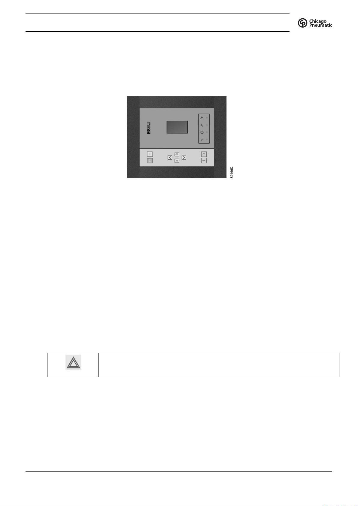
The compressors are controlled by the ES 4000 Standard controller. The ES 4000 Advanced controller is
available as option.
The ES 4000 controller and the emergency stop button are integrated in the door panel of the electric
cubicle. An electric cabinet comprising the motor starter is located behind this panel.
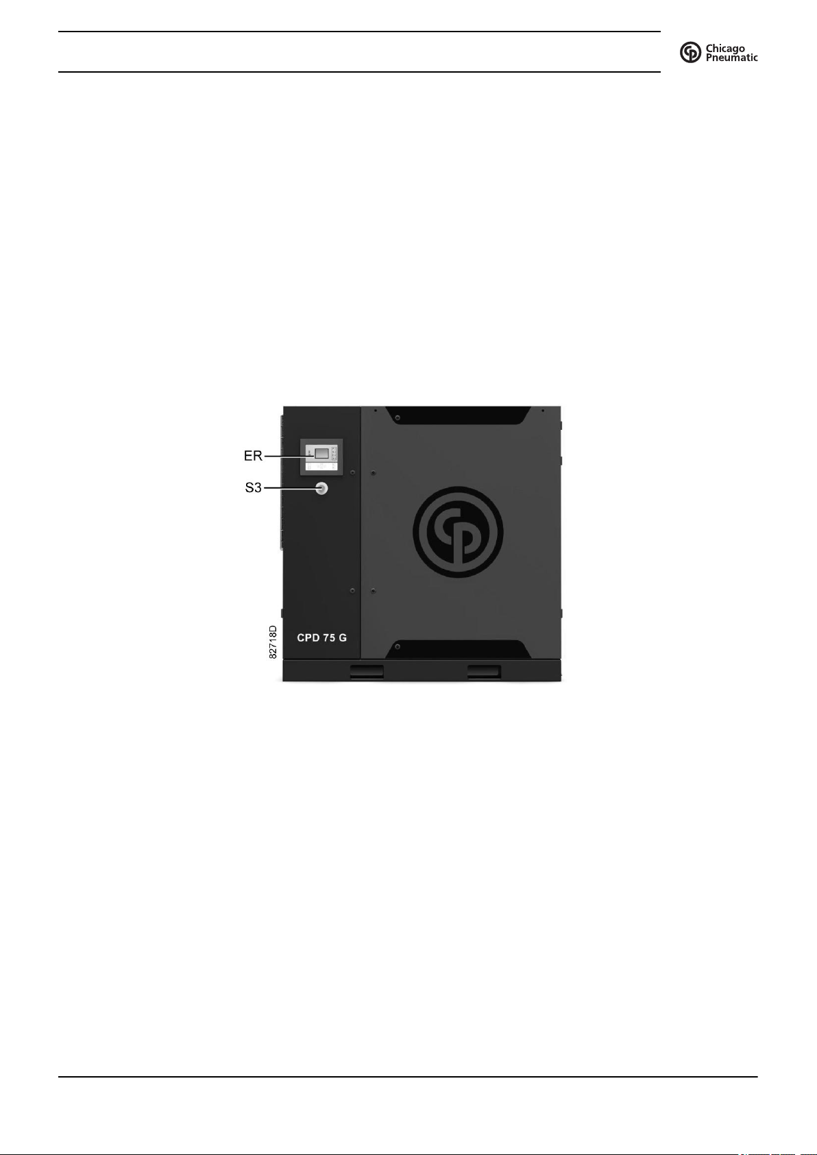
Front view
2920 7101 41 11
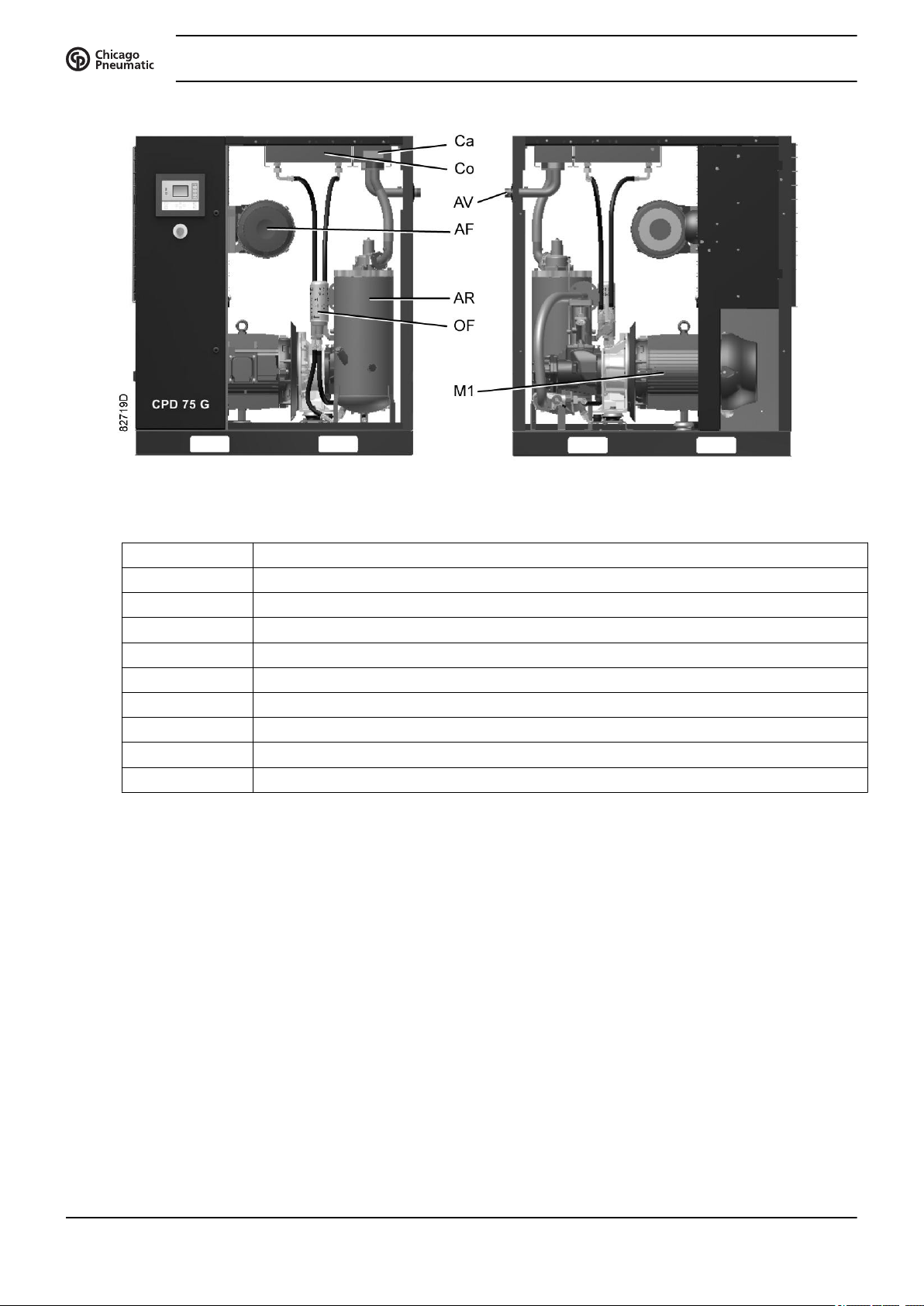
Main components
Instruction book
Ref. Name
AF Air filter
AR Air receiver
AV Location of air outlet valve
Ca Air cooler
Co Oil cooler
ER Controller
M1 Drive motor
OF Oil filter
S3 Emergency stop button
12 2920 7101 41
Instruction book
2.2 Air and oil circuit
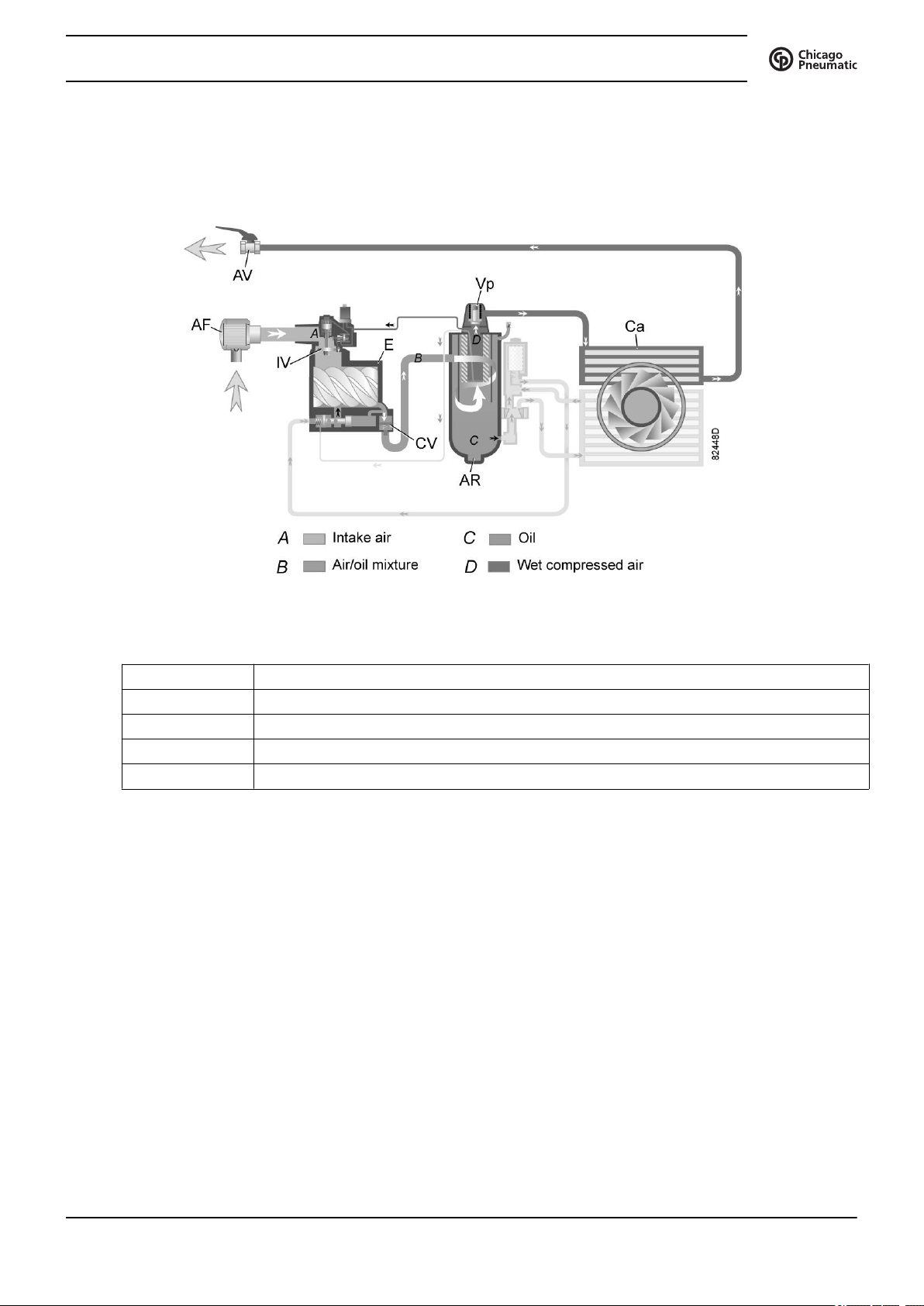
Air circuit
Flow diagram, air circuit
Reference Description
A Intake air
B Air/oil mixture
C Oil
D Wet compressed air
Description
Air drawn through filter (AF) and open inlet valve (IV) into compressor element (E) is compressed. A mix
of compressed air and oil flows into the air receiver/oil separator (AR) via check valve (CV). The air is
discharged through outlet valve (AV) via minimum pressure valve (Vp) and air cooler (Ca).
During loaded operation, minimum pressure valve (Vp) keeps the pressure in the separator tank (AR)
above a minimum value, required for lubrication. An integrated check valve prevents the compressed air
downstream the valve from being vented to atmosphere during unloaded operation. When the compressor
is stopped, check valve (CV) and inlet valve (IV) close, preventing compressed air (and oil) to be vented
into the air filter.
2920 7101 41 13
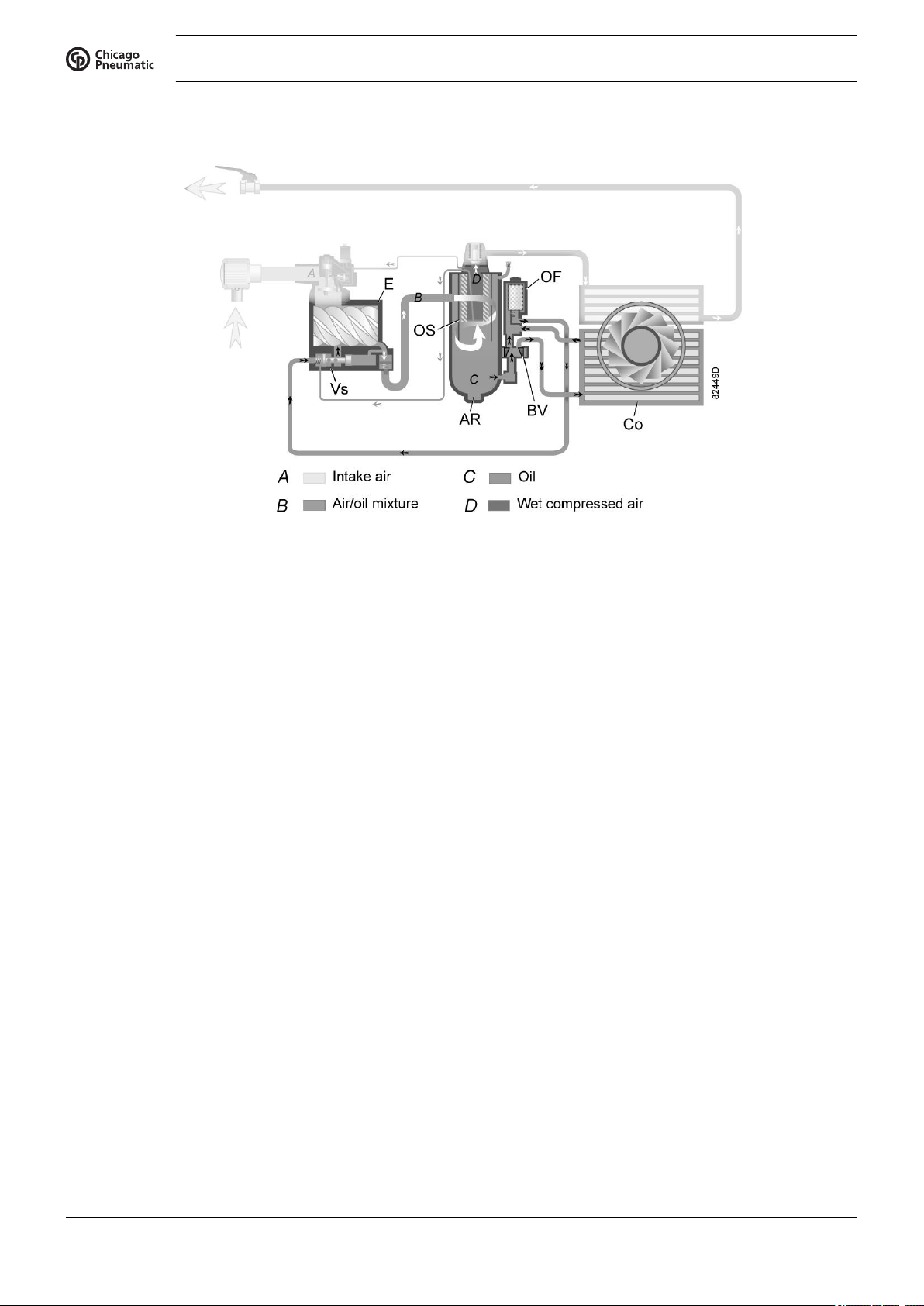
Oil circuit
Instruction book
Flow diagram, oil circuit
Description
In air receiver/oil separator (AR), most of the oil is removed from the air/oil mixture by centrifugal action.
The remaining oil is removed by oil separator (OS). The oil collects in the lower part of air receiver/oil
separator (AR), which serves as an oil tank.
The oil system is provided with a thermostatic bypass valve (BV). When the oil temperature is below its set
point, bypass valve (BV) shuts off the supply to oil cooler (Co) and the oil cooler is bypassed.
Air pressure forces the oil from air receiver/oil separator (AR) through oil filter (OF) and oil stop valve
(Vs) to compressor element (E).
Bypass valve (BV) starts opening the supply from cooler (Co) when the oil temperature has increased to
the set point. At approx. 15 ˚C (27 ˚F) above the set point, all the oil flows through the oil cooler.
Oil stop valve (Vs) prevents the compressor element from flooding with oil when the compressor is
stopped. The valve is opened by element outlet pressure when the compressor is started.
14 2920 7101 41
Instruction book
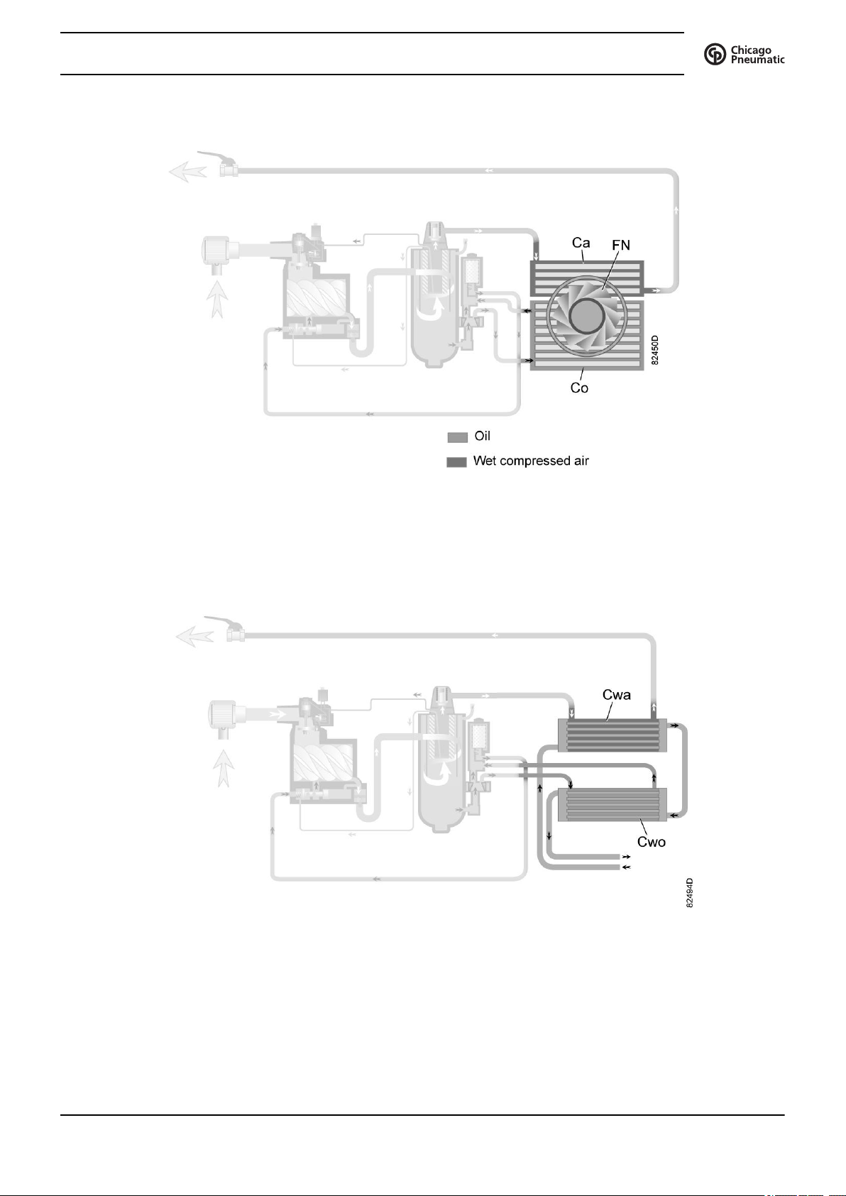
Cooling system
Cooling system air-cooled compressors
The cooling system comprises air cooler (Ca) and oil cooler (Co).
On air-cooled compressors, the cooling air flow is generated by a fan (FN).
Cooling system water-cooled compressors
Water-cooled compressors are connected to a cooling water circuit. The water flows through the inlet pipe
to the air cooler (Cwa), further through the oil cooler (Cwo) to the outlet pipe.
2920 7101 41 15
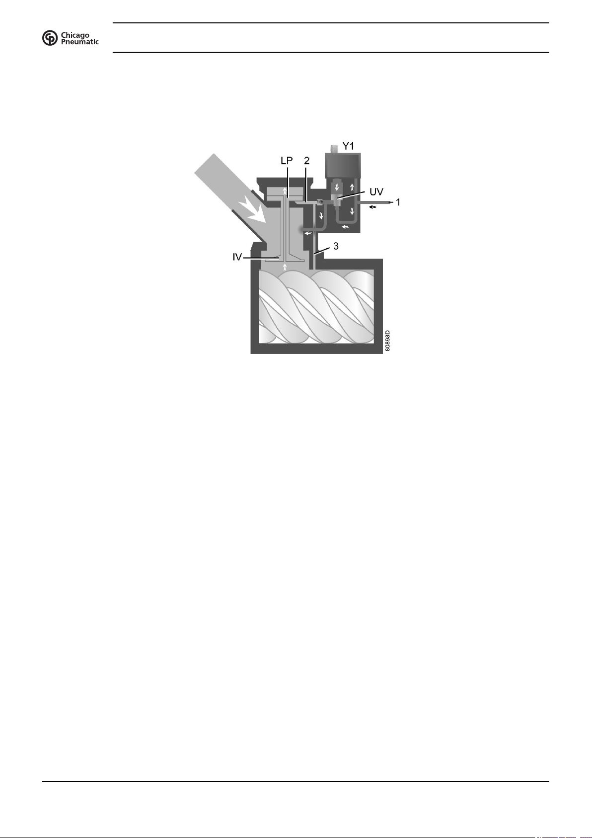
2.3 Regulating system
Load/unload regulating system
Instruction book
Loading
When the net pressure is below the loading pressure, solenoid valve (Y1) is energised. Results:
Air delivery is 100%, the compressor runs loaded.
Unloading
If the air consumption is less than the air output of the compressor, the net pressure increases. When the net
pressure reaches the unloading pressure, solenoid valve (Y1) is de-energised. Results:
Regulating system (loaded condition)
• The space above unloading valve/blow-off valve (UV) is connected with the oil separator tank
pressure (1) via the solenoid valve.
• Unloading valve/blow-off valve (UV) moves downwards, closing off the connection to channels (2)
and (3).
• Underpressure from the compressor element causes loading plunger (LP) to move downwards and
inlet valve (IV) to open fully.
• The pressure above unloading valve/blow-off valve (UV) is released to atmosphere and the space
above valve (UV) is no longer in connection with the oil separator tank pressure (1).
• Unloading valve/blow-off valve (UV) moves upwards, connecting the oil separator tank pressure (1)
with channels (2) and (3).
• The pressure in channel (2) causes the loading plunger (LP) to move upwards, causing inlet valve
(IV) to close, while the pressure is gradually released to atmosphere.
• The pressure in the separator tank stabilises at low value. A small amount of air is kept drawn in to
guarantee a minimal pressure, required for lubrication during unloaded operation.
Air output is stopped, the compressor runs unloaded.
16 2920 7101 41
Instruction book
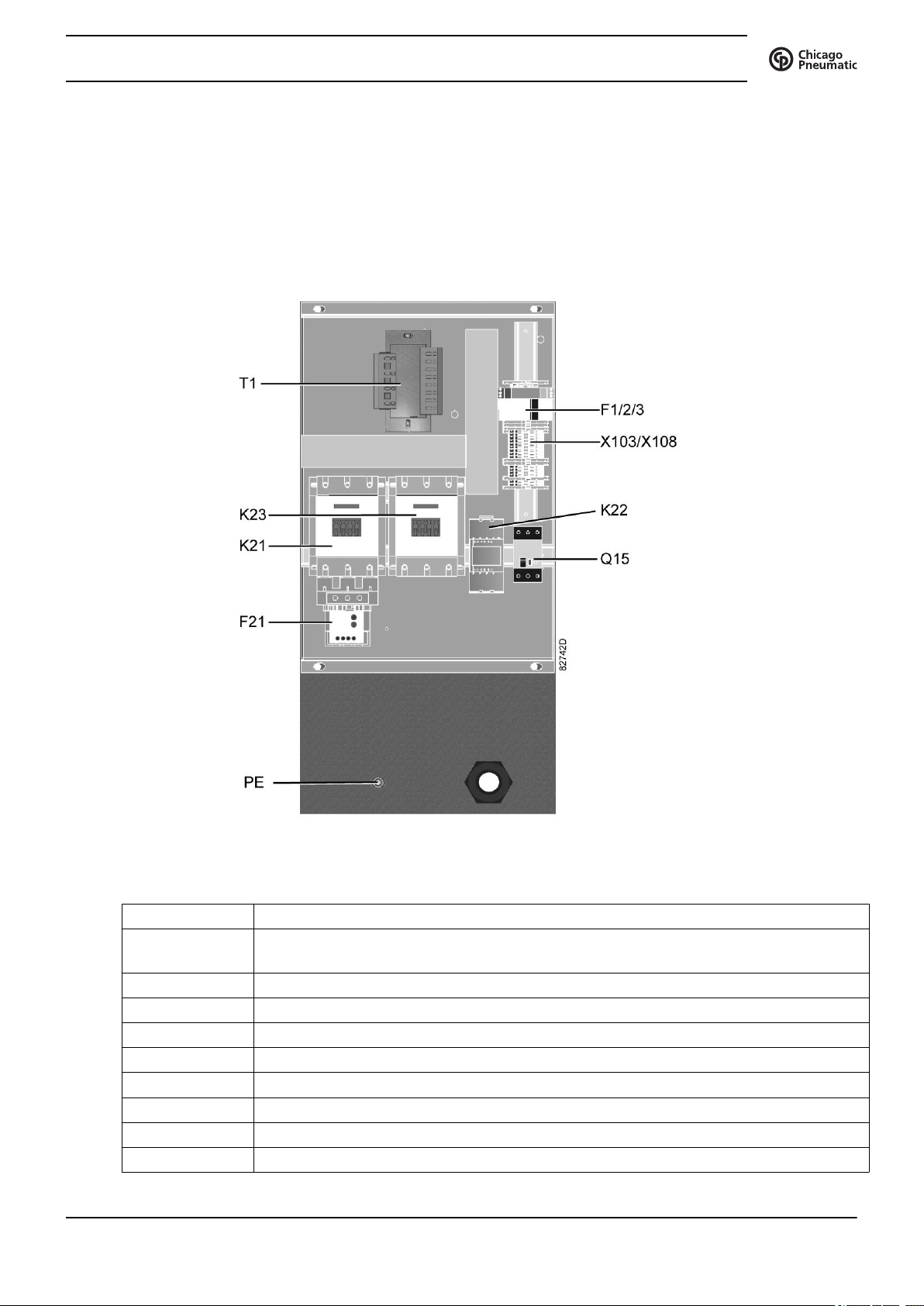
2.4 Electrical system
General
Electrical components
The electrical system comprises following components:
Electric cubicle, typical example
Reference Designation
F1/2/3 Fuses
(F3 is only provided in case a phase sequence relay is provided)
F21 Overload relay, compressor motor
Q15 Circuit breaker, fan motor (on air-cooled compressors)
K21 Line contactor
K22 Star contactor
K23 Delta contactor
T1 Transformer
X103/X108 Connectors
PE Earth terminal
2920 7101 41 17

Electrical diagram
There is a copy of the electrical diagram inside the electrical cubicle.
Instruction book
18 2920 7101 41
Instruction book
3 Controller
3.1 Controller
View of the ES 4000 Standard controller
Introduction
The electronic controller has following functions:
• Controlling the compressor
• Protecting the compressor
• Monitoring components subject to service
• Automatic restart after voltage failure
Automatic control of the compressor
The controller maintains the net pressure between programmable limits by automatically loading and
unloading the compressor. A number of programmable settings, e.g. the unloading and loading pressures,
the minimum stop time and the maximum number of motor starts are taken into account.
The controller stops the compressor whenever possible to reduce the power consumption and restarts it
automatically when the net pressure decreases. If the expected unloading period is to short, the compressor
is kept running to prevent too short stand-still periods.
A number of time based automatic start/stop commands may be programmed. Take into
account that a start command will be executed (if programmed and activated), even after
manually stopping the compressor.
Protecting the compressor
Shut-down
Several sensors are provided on the compressor. If one of the measured signals exceeds the programmed
shutdown level, the compressor will be stopped.
Example: If the compressor element outlet temperature exceeds the programmed shut-down level, the
compressor will be stopped. This will be indicated on the display of the controller. The compressor will
also be stopped in case of overload of the drive motor.
2920 7101 41 19
Air-cooled compressors will also be stopped in the event of overload of the fan motor.
Before remedying, consult the Safety precautions.
Shut-down warning
A shut-down warning level is a programmable level below the shut-down level.
If one of the measurements exceeds the programmed shut-down warning level, this will also be indicated to
warn the operator before the shut-down level is reached.
Service warning
If the service timer exceeds a programmed value, this will be indicated on the display to warn the operator
to carry out some service actions.
Automatic restart after voltage failure
The controller has a built-in function to automatically restart the compressor when the voltage is restored
after voltage failure. For compressors leaving the factory, this function is made inactive. If desired, the
function can be activated.
Instruction book
If the function is activated and provided the regulator was in the automatic operation
mode, the compressor will automatically restart if the supply voltage to the module is
restored.
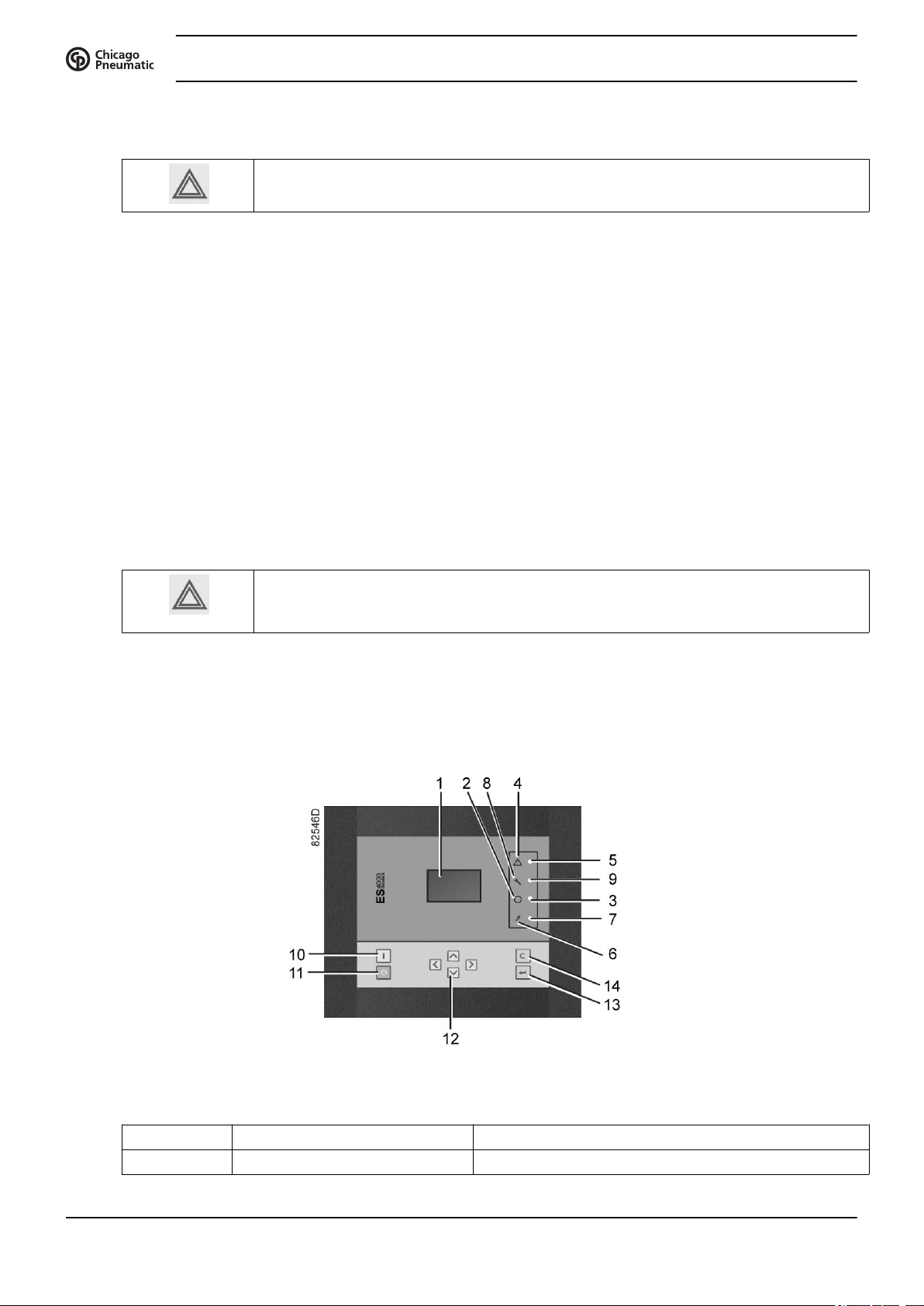
3.2 Control panel
Detailed description
Function keys of the controller
Reference Designation Function
1 Display Shows icons and operating conditions.
20 2920 7101 41
Instruction book
Reference Designation Function
2 Automatic operation symbol
3 LED, Automatic operation Indicates that the regulator is automatically controlling
4 Warning symbol
5 LED, Warning Flashes in case of a shut-down, is lit in case of a
6 Voltage symbol
7 LED, Voltage on Indicates that the voltage is switched on.
8 Service symbol
9 LED, Service Is lit when service is needed.
10 Start button This button starts the compressor. Automatic operation
11 Stop button This button is used to stop the compressor. Automatic
12 Scroll buttons Use these buttons to scroll through the menu.
13 Enter button Use this button to confirm the last action.
14 Escape button Use this button to go to previous screen or to end the
the compressor: the compressor is loaded, unloaded,
stopped and restarted depending on the air
consumption and the limitations programmed in the
regulator.
warning condition.
LED (3) lights up. The controller is operative.
operation LED (3) goes out.
current action.
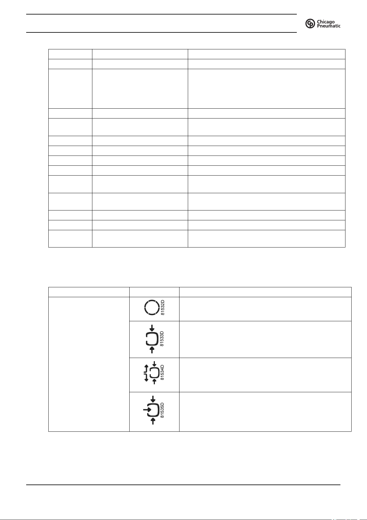
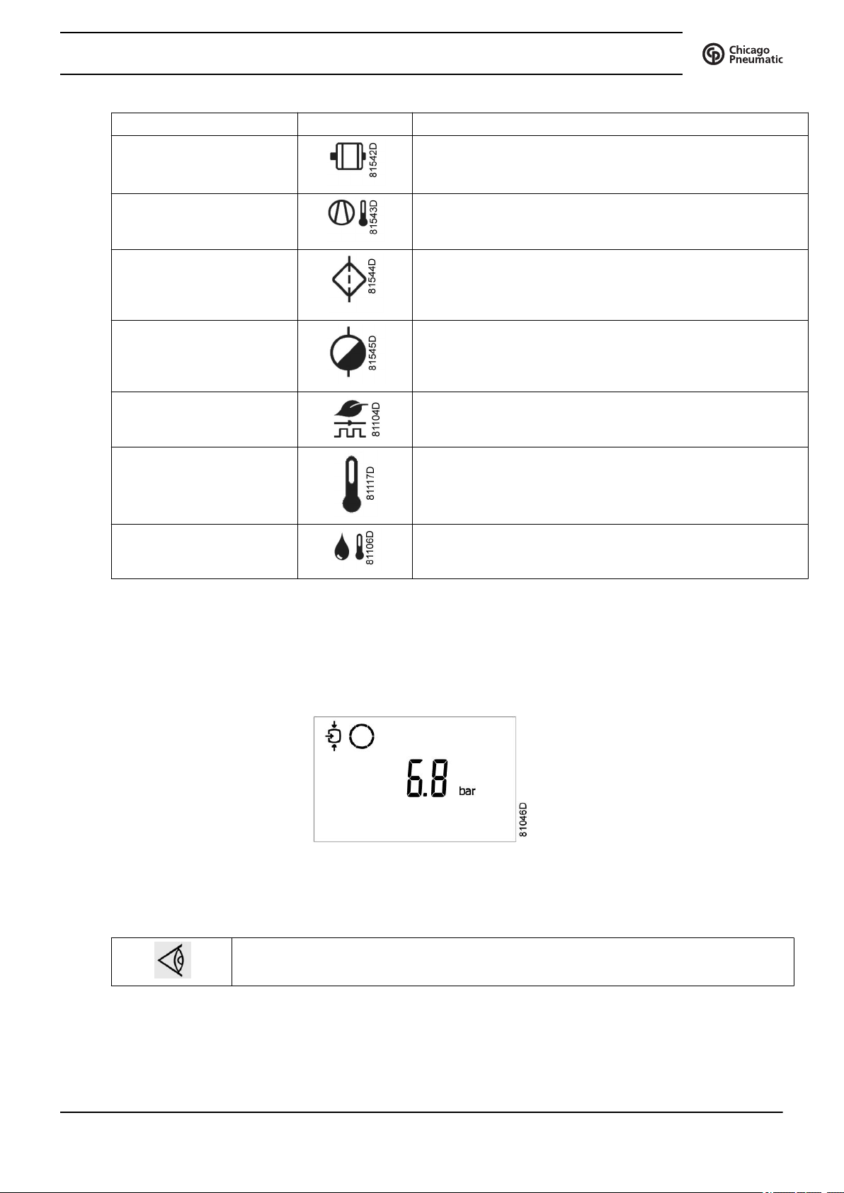
3.3 Icons used on the display
Function Icon Description
Compressor status When the compressor is stopped, the icon stands still.
When the compressor is running, the icon is rotating.
Motor stopped
Running unloaded
Running loaded
2920 7101 41 21
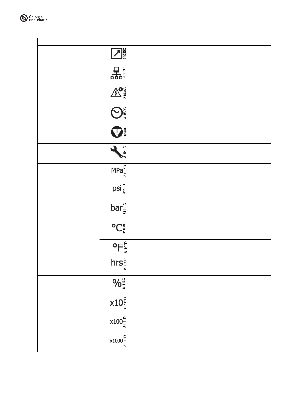
Function Icon Description
Machine control mode Remote start / stop
LAN control
Instruction book
Automatic restart after
voltage failure
Timer
Active protection functions Emergency stop
Service Service required
Units Pressure unit (Mega Pascal)
Automatic restart after voltage failure is active
Pressure unit (pounds per square inch)
Pressure unit (bar)
Temperature unit
Temperature unit
Hours (always shown together with seconds)
Percent
The value shown must be multiplied by 10 to get the actual
value
The value shown must be multiplied by 100 to get the actual
value
The value shown must be multiplied by 1000 to get the actual
value
22 2920 7101 41
Instruction book
Function Icon Description
Motor (overload)
Element outlet temperature.
Filter
Drain
Energy saving (dryer)
Ambient temperature
Dewpoint temperature
3.4 Main screen
When the voltage is switched on, the first screen is a test screen. The next screen is the Main screen, shown
automatically.
The Main screen shows:
• The compressor status by means of pictographs
• The air outlet pressure
Always consult your supplier if the pressure on the display is preceded by a "t".
2920 7101 41 23
3.5 Shut-down warning
Description
A shut-down warning will appear in the event of:
• Too high a temperature at the outlet of the compressor element
• Too high a dewpoint temperature (Full-Feature compressors)
Compressor element outlet temperature
• If the outlet temperature of the compressor element exceeds the shut-down warning level (see section
Programmable settings), warning LED (5) starts blinking.
• Press the Scroll down button. The screen shows the temperature at the compressor element outlet:
Instruction book
It remains possible to scroll through other screens, using the Scroll buttons up and down (12) to check the
actual status of other parameters. Press button (11) to stop the compressor and wait until the compressor
has stopped. Switch off the voltage, inspect the compressor and remedy. The warning message will
disappear as soon if the warning condition disappears.
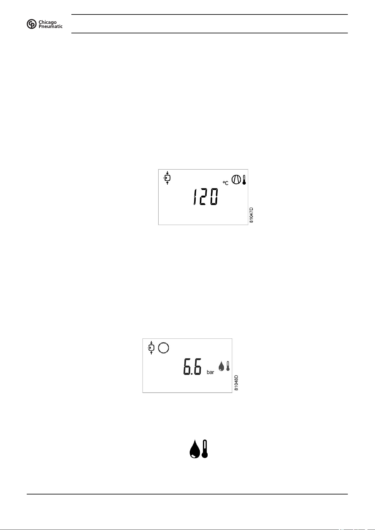
Dewpoint temperature
On compressors with integrated dryer, alarm LED (5) will light up and the related pictograph will appear
flashing if the dewpoint temperature exceeds the warning level (programmable).
The screen shows that the temperature at the element outlet is 120 °C
Main screen with the dewpoint temperature warning
The related pictograph
will appear flashing
Press the Scroll button (12) until the actual dewpoint temperature appears.
24 2920 7101 41
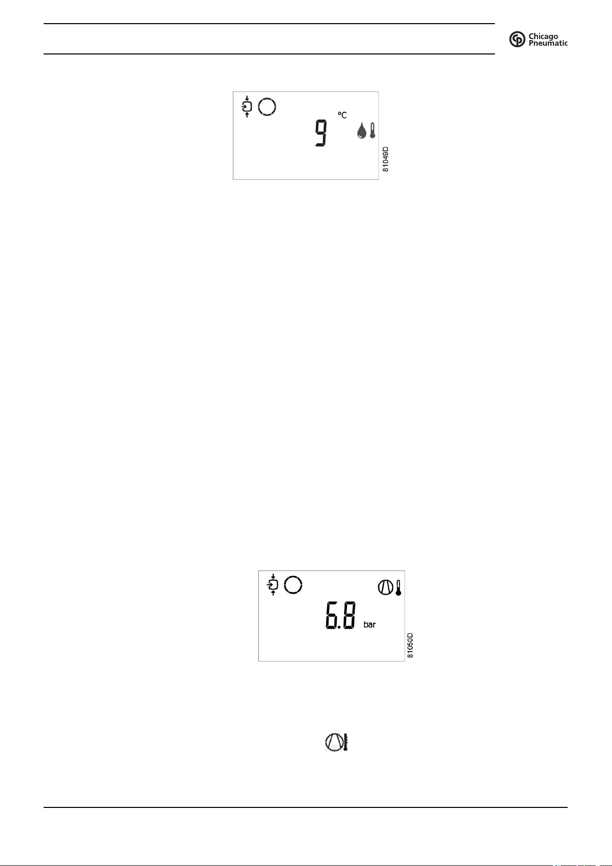
Instruction book
The screen shows that the dewpoint temperature is 9˚C.
• It remains possible to scroll through other screens (using Scroll buttons 12) to check the actual status
of other parameters.
• Press button (11) to stop the compressor and wait until the compressor has stopped.
• Switch off the voltage, inspect the compressor and remedy.
• The warning message will disappear as soon as the warning condition disappears.
Warning screen, dewpoint temperature
3.6 Shut-down
Description
The compressor will be shut down:
• In case the temperature at the outlet of the compressor element exceeds the shut-down level
• In case of error of the outlet pressure sensor
• In case of overload of the drive motor
• In case of overload of the fan motor on air-cooled compressors
Compressor element outlet temperature
• If the outlet temperature of the compressor element exceeds the shut-down level (factory setting 120
˚C / 248 ˚F, programmable) the compressor will be shut-down, alarm LED (5) will flash, automatic
operation LED (3) will go out and the following screen will appear:
Main screen with shut-down indication, element outlet temperature
The related pictograph
will appear flashing.
• Press Scroll buttons (12) until the actual compressor element temperature appears.
2920 7101 41 25
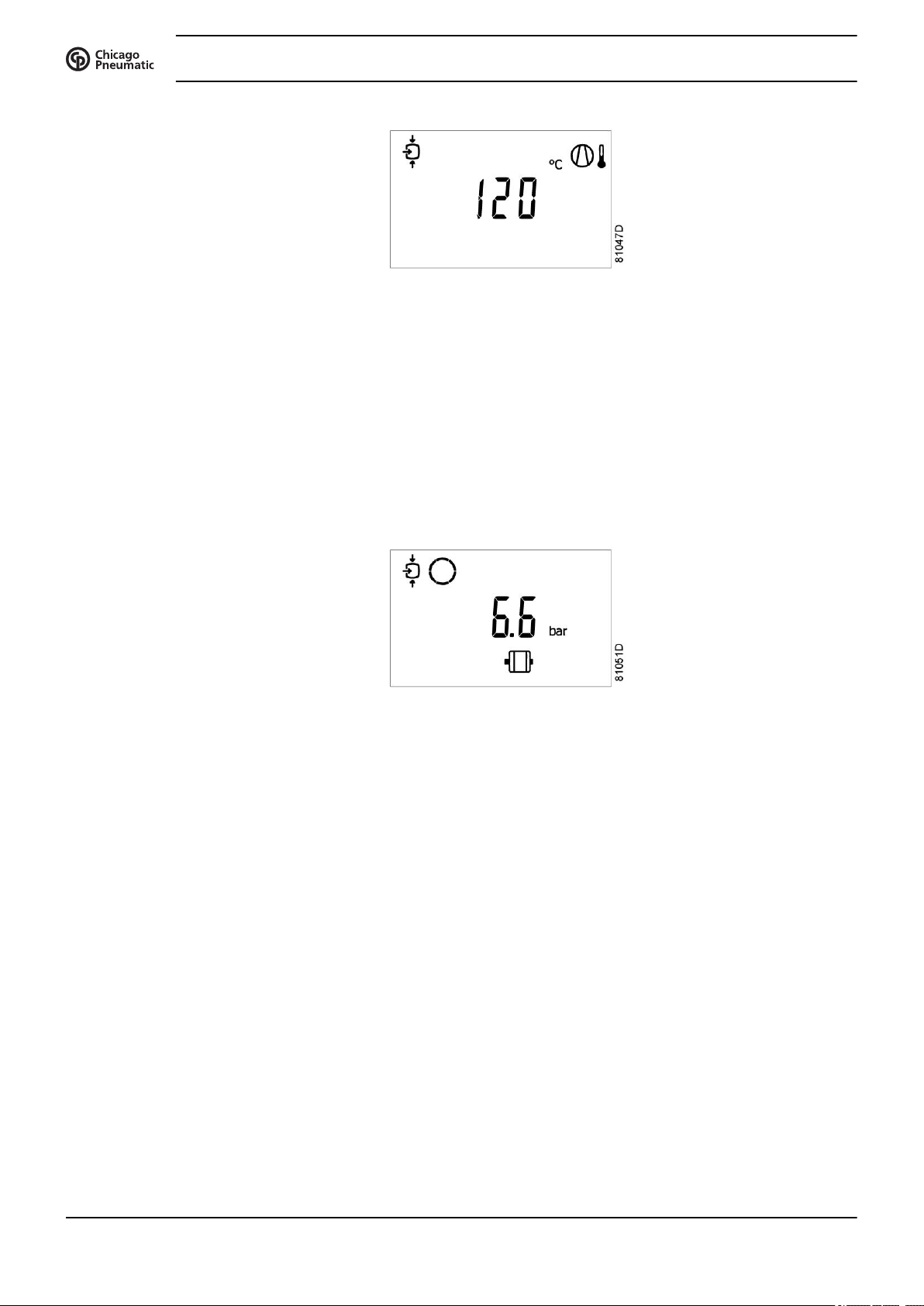
The screen shows that the temperature at the outlet of the compressor element is 120 ˚C.
• Switch off the voltage and remedy the trouble.
• After remedying and when the shut-down condition has disappeared, switch on the voltage and restart
the compressor.
Motor overload
• In the event of motor overload, the compressor will be shut-down, alarm LED (5) will flash,
automatic operation LED (3) will go out and the following screen will appear:
Instruction book
Shut-down screen, element outlet temperature
• Switch off the voltage and remedy the trouble.
• After remedying and when the shut-down condition has disappeared, switch on the voltage and restart
the compressor.
3.7 Service warning
Description
A service warning will appear when the service timer has reached the programmed time interval.
• If the service timer exceeds the programmed time interval, alarm LED (5) will light up.
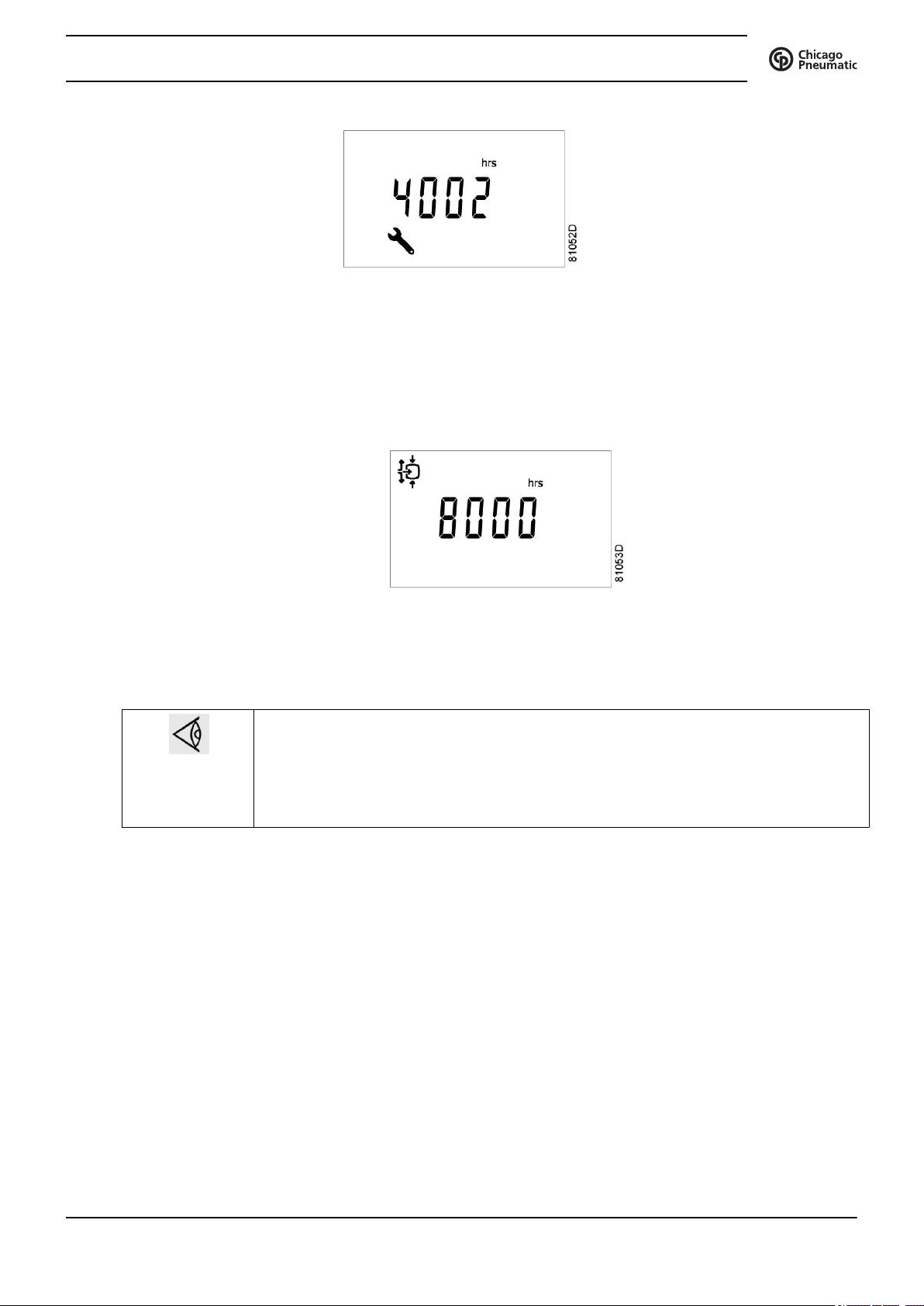
• Press Scroll buttons (12) to scroll to <d.6> and the service symbol is shown. Press button (13): the
actual reading of the service timer appears and is shown in <hrs> or <x1000 hrs> (if the service timer
value is higher than 9999).
Main screen with shut-down indication, motor overload
26 2920 7101 41
Instruction book
The screen shows that the reading of the service timer is 4002.
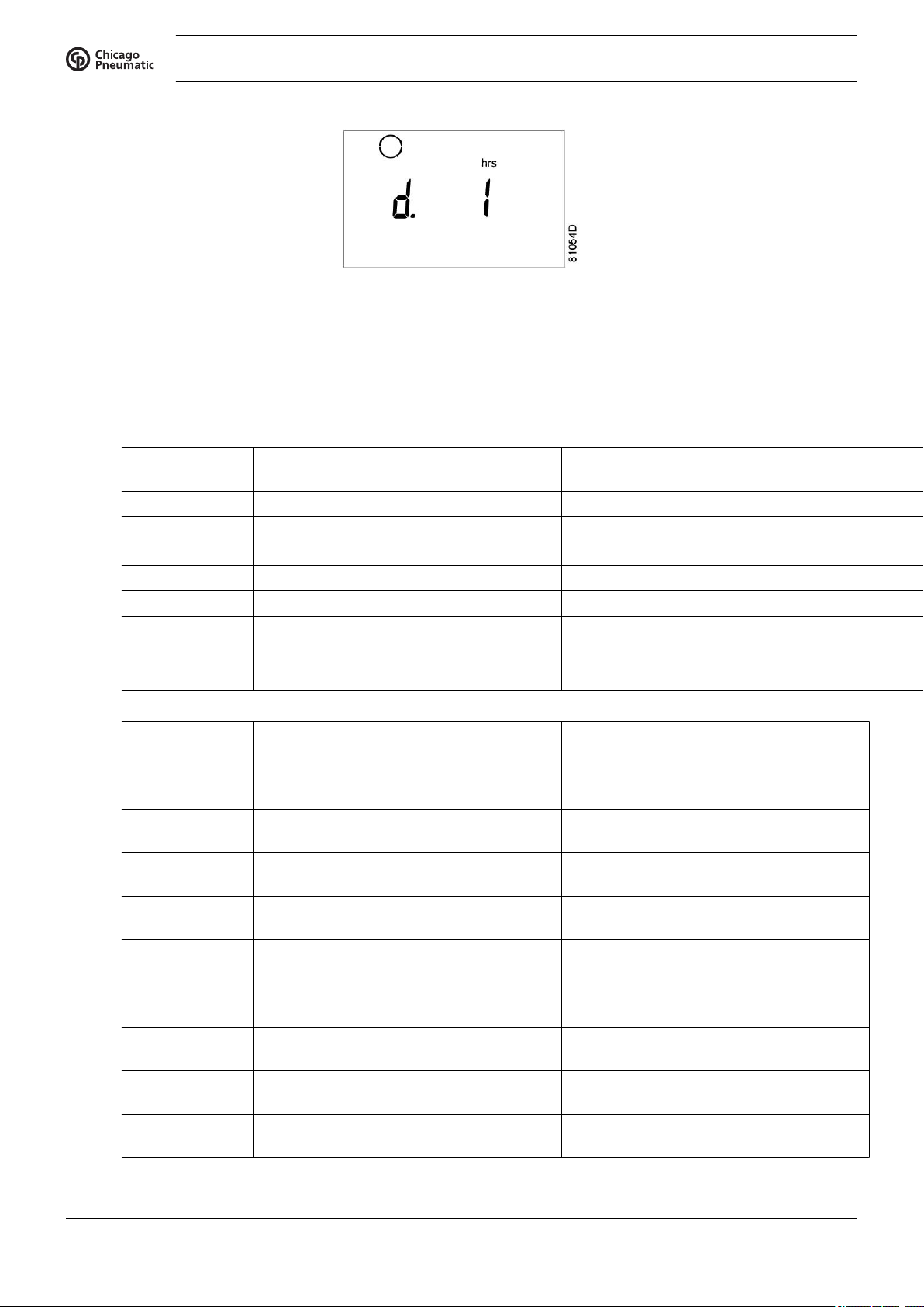
• Press Scroll button (12) to scroll to <d.1> and the running hours symbol is shown. Press button (13):
the actual reading of the service timer appears and is shown in <hrs> or <x1000 hrs> (if the service
timer value is higher than 9999).
Example of service timer screen
Example of running hours screen
• Stop the compressor, switch off the voltage and carry out the required service actions. See section
Preventive Maintenance.
• The longer interval service actions must also include the shorter interval actions.
In the example above, carry out all service operations belonging to the 8000
running hours interval as well as those belonging to the 4000 running hours
interval.
• The setting of the service timer can be changed in function of the operating
conditions. See section Preventive maintenance schedule.
• After servicing, reset the service timer. See section Calling up/ resetting the service timer
3.8 Scrolling through all screens
Scroll buttons (12) can be used to scroll through all screens. The screens are divided into register screens,
measured data screens, digital input screens (numbered as <d.in>, <d.1>, ...), parameter screens (numbered
as <P.01>, <P.02>, ...), protections screens (numbered as <Pr.01>,...) and test screens (numbered as <t.
01>,...).
During scrolling, the numbers of the screens appear consecutively. For most screens, the unit of
measurement and the related pictograph are shown together with the screen number.
2920 7101 41 27
The screen shows the screen number <d.1>, the unit used <hrs> and the related symbol for running hours.
Press Enter key (13) to call up the actual running hours.
Overview of the screens
Instruction book
Example
Digital input
screens
<d.in> Digital input status
<d.1> Running hours (hrs or x 1000 hrs) See section Calling up running hours
<d.2> Motor starts (x 1 or x 1000) See section Calling up motor starts
<d.3> Module hours (hrs or x 1000 hrs) See section Calling up module hours
<d.4> Loading hours (hrs or x1000 hrs) See section Calling up loading hours
<d.5> Load relay (x1 or x 1000) See section Calling up Calling up load relay
<d.6> Service timer reading (hrs or x 1000 hrs) See section Calling up resetting the service timer
<d.7> Actual program version
Parameter
screens
<P.01> Selection between local, remote or LAN
<P.02> Setting a node ID for LAN control and the
<P.03> Settings for IP, gateway and Subnet mask See section Calling up modifying IP
<P.04> Pressure band settings See section Calling up modifying pressure
<P.05> Setting a pressure band selection See section Modifying the pressure band
<P.06> Modifying a service timer See section Calling up modifying service
<P.07> Setting of unit for temperature See section Calling up/modifying unit of
<P.08> Setting of unit for pressure See section Calling up modifying unit of
<P.09> Selection for function: Automatic restart
Designation Related topic
Designation Related topic
See section Selection between local
control
channels for Mk 4 and Mk 5
after voltage failure
remote or LAN
See section Calling up/modifying CAN
address control
Gateway and Subnetmask
band settings
selection
timer settings
temperature
pressure
See section Activating automatic restart
28 2920 7101 41
 Loading...