

Chicago Pneumatic CP 550, CP 750, CP 1650, CP 2250, CP 3050 Operating Instructions Manual
...
Operating instructions
for hydraulic breaker
TM
CP 550
CP 750
CP 1150
CP 1650
CP 2250
CP 3050
CP 4250
© Copyright 2007
www.chicagopneumatic.com
AIB
2007−05−04
No. 3390 5053 01


Operating instructions for hydraulic breaker
CP 550
CP 750
CP 1150
CP 1650
CP 2250
CP 3050
CP 4250
E Chicago Pneumatic
Any unauthorized use or copying of contents or any part thereof is
prohibited.This applies in particular to to trademarks, model denominations,
part numbers and drawings.
3

Table of contents
1 Foreword 6 . . . . . . . . . . . . . . . . . . . . . . . . . . . . . . . . . . . . . . . . . . . . . . . . . . . . . . . . . . . . . . . . . . .
2 Accident prevention regulations 7 . . . . . . . . . . . . . . . . . . . . . . . . . . . . . .
3CE markings EC machinery directive 98/37/EC 10 . . . . . . . . . . . . . . . . . . . . . . . . . . . . .
3.1CE sticker product groups A 10 . . . . . . . . . . . . . . . . . . . . . . . . . . . . . . . . . . . . . . . . . . . . . . . . . .
3.2 CE sticker product groups B 10 . . . . . . . . . . . . . . . . . . . . . . . . . . . . . . . . . . . . . . . . . . . . . . . . . .
3.3 Sticker for guaranteed sound level power11 . . . . . . . . . . . . . . . . . . . . . . . . . . . . . . . . . . . . . . .
4 General informations 11 . . . . . . . . . . . . . . . . . . . . . . . . . . . . . . . . . . . . . . . . . . . . . . . . . . . . . . . .
4.1 Applications 11 . . . . . . . . . . . . . . . . . . . . . . . . . . . . . . . . . . . . . . . . . . . . . . . . . . . . . . . . . . . . . . . .
4.2 Scope of supply 11 . . . . . . . . . . . . . . . . . . . . . . . . . . . . . . . . . . . . . . . . . . . . . . . . . . . . . . . . . . . .
5 Main components 12 . . . . . . . . . . . . . . . . . . . . . . . . . . . . . . . . . . . . . . . . . . . . . . . . . . . . . . . . . . .
5.1 Main components or assemblies CP 550 and CP 750 12 . . . . . . . . . . . . . . . . . . . . . . . . . . . .
5.2 Main components or assemblies CP 1150 and CP 1650 13 . . . . . . . . . . . . . . . . . . . . . . . . . .
5.3 Main components or assemblies, CP 2250, CP3050 and CP 4250 14 . . . . . . . . . . . . . . . .
6 Installation 15 . . . . . . . . . . . . . . . . . . . . . . . . . . . . . . . . . . . . . . . . . . . . . . . . . . . . . . . . . . . . . . . . .
6.1 Media/consumables 15 . . . . . . . . . . . . . . . . . . . . . . . . . . . . . . . . . . . . . . . . . . . . . . . . . . . . . . . . .
6.1.1 Mineral hydraulic oil 15 . . . . . . . . . . . . . . . . . . . . . . . . . . . . . . . . . . . . . . . . . . . . . . . . . . . . . . . . .
6.1.2 Non−mineral hydraulic oil 15 . . . . . . . . . . . . . . . . . . . . . . . . . . . . . . . . . . . . . . . . . . . . . . . . . . . . .
6.1.3 Grease 15 . . . . . . . . . . . . . . . . . . . . . . . . . . . . . . . . . . . . . . . . . . . . . . . . . . . . . . . . . . . . . . . . . . . .
6.1.4 Gas 16 . . . . . . . . . . . . . . . . . . . . . . . . . . . . . . . . . . . . . . . . . . . . . . . . . . . . . . . . . . . . . . . . . . . . . . .
6.2 Attaching the adapter to the hydraulic breaker16 . . . . . . . . . . . . . . . . . . . . . . . . . . . . . . . . . .
6.3 Mounting the hydraulic breaker on the excavatormechanical aspects 17 . . . . . . . . . . . . . .
6.4 Mounting the hydraulic breaker on the excavator−hydraulic aspects 18 . . . . . . . . . . . . . . . .
6.5 Switching the hydraulic breaker on/off from the carrier19 . . . . . . . . . . . . . . . . . . . . . . . . . . .
6.6Dismounting the hydraulic breaker from the excavator for short or
lengthy periods of nonuse 19 . . . . . . . . . . . . . . . . . . . . . . . . . . . . . . . . . . . . . . . . . . . . . . . . . . .
6.6.1Dismounting from excavator19 . . . . . . . . . . . . . . . . . . . . . . . . . . . . . . . . . . . . . . . . . . . . . . . . . .
7 Storage 20 . . . . . . . . . . . . . . . . . . . . . . . . . . . . . . . . . . . . . . . . . . . . . . . . . . . . . . . . . . . . . . . . . . . .
7.1Hydraulic breaker 20 . . . . . . . . . . . . . . . . . . . . . . . . . . . . . . . . . . . . . . . . . . . . . . . . . . . . . . . . . . .
7.1.1Short storage 20 . . . . . . . . . . . . . . . . . . . . . . . . . . . . . . . . . . . . . . . . . . . . . . . . . . . . . . . . . . . . . . .
7.1.2 Long storage 20 . . . . . . . . . . . . . . . . . . . . . . . . . . . . . . . . . . . . . . . . . . . . . . . . . . . . . . . . . . . . . . .
7.1.3 How to proceed after more than twelve months’ storage 20 . . . . . . . . . . . . . . . . . . . . . . . . . .
7.1.4 Working tool 21 . . . . . . . . . . . . . . . . . . . . . . . . . . . . . . . . . . . . . . . . . . . . . . . . . . . . . . . . . . . . . . . .
8 Fitting/removing the working tool 22 . . . . . . . . . . . . . . . . . . . . . . . . . . . . . . . . . . . . . . . . . . . .
8.1Selecting the right working tool 22 . . . . . . . . . . . . . . . . . . . . . . . . . . . . . . . . . . . . . . . . . . . . . . .
8.1.1Working tools for hydraulic breakers CP 550 22 . . . . . . . . . . . . . . . . . . . . . . . . . . . . . . . . . . . .
8.1.2 Working tools for hydraulic breakers CP 750 22 . . . . . . . . . . . . . . . . . . . . . . . . . . . . . . . . . . . .
8.1.3 Working tools for hydraulic breakers CP 1150 CP 4250 23 . . . . . . . . . . . . . . . . . . . . . . . . .
8.2 Fitting the tool (After breaker delivery to the site) 24 . . . . . . . . . . . . . . . . . . . . . . . . . . . . . . . .
8.2.1CP 550 and CP 750 24 . . . . . . . . . . . . . . . . . . . . . . . . . . . . . . . . . . . . . . . . . . . . . . . . . . . . . . . . .
8.2.2 CP 1150 CP 4250 25 . . . . . . . . . . . . . . . . . . . . . . . . . . . . . . . . . . . . . . . . . . . . . . . . . . . . . . . . .
8.3 Removing the tool 25 . . . . . . . . . . . . . . . . . . . . . . . . . . . . . . . . . . . . . . . . . . . . . . . . . . . . . . . . . . .
9 Operating the hydraulic breaker 26 . . . . . . . . . . . . . . . . . . . . . . . . . . . . . . . . . . . . . . . . . . . . .
9.1Starting up the hydraulic breaker 26 . . . . . . . . . . . . . . . . . . . . . . . . . . . . . . . . . . . . . . . . . . . . . .
9.2 Advance 26 . . . . . . . . . . . . . . . . . . . . . . . . . . . . . . . . . . . . . . . . . . . . . . . . . . . . . . . . . . . . . . . . . . .
9.3 Angle of attack 27 . . . . . . . . . . . . . . . . . . . . . . . . . . . . . . . . . . . . . . . . . . . . . . . . . . . . . . . . . . . . .
9.4 Breaker rocking 27 . . . . . . . . . . . . . . . . . . . . . . . . . . . . . . . . . . . . . . . . . . . . . . . . . . . . . . . . . . . . .
9.5 Never drive the working tool into the ground 27 . . . . . . . . . . . . . . . . . . . . . . . . . . . . . . . . . . . .
9.6Never lever with the breaker 27 . . . . . . . . . . . . . . . . . . . . . . . . . . . . . . . . . . . . . . . . . . . . . . . . . .
. . . . . . . . . . . . . . .
. . .
4

9.7 Never use as a sledgehammer 28 . . . . . . . . . . . . . . . . . . . . . . . . . . . . . . . . . . . . . . . . . . . . . . .
9.8Never use for transport purposes 28 . . . . . . . . . . . . . . . . . . . . . . . . . . . . . . . . . . . . . . . . . . . . .
9.9Using the hydraulic breaker in or under water 28 . . . . . . . . . . . . . . . . . . . . . . . . . . . . . . . . . . .
9.10 Hydraulic breaker used in tunnelling 29 . . . . . . . . . . . . . . . . . . . . . . . . . . . . . . . . . . . . . . . . . . .
9.11 Working in high outside temperatures 29 . . . . . . . . . . . . . . . . . . . . . . . . . . . . . . . . . . . . . . . . . .
9.12 Working in low outside temperatures 29 . . . . . . . . . . . . . . . . . . . . . . . . . . . . . . . . . . . . . . . . . .
9.13 Operating the breaker with the cylinders fully extended or retracted 29 . . . . . . . . . . . . . . . .
10 Maintenance work to be performed by the excavator driver 30 . . . . . . . . . . . . . . . . . . . .
10.1 Manual lubricating of the working tool for CP550 30 . . . . . . . . . . . . . . . . . . . . . . . . . . . . . . . .
10.2 Automatic lubrication using of the hydraulic breaker 31 . . . . . . . . . . . . . . . . . . . . . . . . . . . . .
10.2.1 Automatic lubrication using CP−Lube 31 . . . . . . . . . . . . . . . . . . . . . . . . . . . . . . . . . . . . . . . . . .
10.2.2 Changing the lubricant cartridge 31 . . . . . . . . . . . . . . . . . . . . . . . . . . . . . . . . . . . . . . . . . . . . . .
10.2.3 Operating the CP−Lube 31 . . . . . . . . . . . . . . . . . . . . . . . . . . . . . . . . . . . . . . . . . . . . . . . . . . . . . .
10.3 Manual lubrication without or upon failure of CP−Lube 32 . . . . . . . . . . . . . . . . . . . . . . . . . . . .
10.3.1 Filling device for the chisel paste 32 . . . . . . . . . . . . . . . . . . . . . . . . . . . . . . . . . . . . . . . . . . . . . .
10.4 Care and maintenance timetable33 . . . . . . . . . . . . . . . . . . . . . . . . . . . . . . . . . . . . . . . . . . . . . .
10.5 Check 34 . . . . . . . . . . . . . . . . . . . . . . . . . . . . . . . . . . . . . . . . . . . . . . . . . . . . . . . . . . . . . . . . . . . . .
10.5.1Checking the working tool for wear 34 . . . . . . . . . . . . . . . . . . . . . . . . . . . . . . . . . . . . . . . . . . . .
10.5.2 Checking the wear bushes 35 . . . . . . . . . . . . . . . . . . . . . . . . . . . . . . . . . . . . . . . . . . . . . . . . . . .
10.5.3 Checking the retaining pin for wear (CP 550 and CP 750) 36 . . . . . . . . . . . . . . . . . . . . . . . .
10.5.4 Checking the retainer bars (CP 1150 CP 4250) 36 . . . . . . . . . . . . . . . . . . . . . . . . . . . . . . . .
10.5.5 Checking the impact face of the percussion piston 36 . . . . . . . . . . . . . . . . . . . . . . . . . . . . . . .
10.5.6Checking the breaker box for wear and cracks and checking the
adapter for cracks 36 . . . . . . . . . . . . . . . . . . . . . . . . . . . . . . . . . . . . . . . . . . . . . . . . . . . . . . . . . . .
10.5.7 Screw couplings CP 550 and CP 750 37 . . . . . . . . . . . . . . . . . . . . . . . . . . . . . . . . . . . . . . . . . .
10.5.8Screw couplings CP 1150 38 . . . . . . . . . . . . . . . . . . . . . . . . . . . . . . . . . . . . . . . . . . . . . . . . . . . .
10.5.9Screw couplings CP 1650 39 . . . . . . . . . . . . . . . . . . . . . . . . . . . . . . . . . . . . . . . . . . . . . . . . . . . .
10.5.10 Screw couplings CP 2250, CP 3050 and CP 4250 40 . . . . . . . . . . . . . . . . . . . . . . . . . . . . . . .
10.5.11 Checking pressure in piston accumulator and refilling if required 42 . . . . . . . . . . . . . . . . . . .
10.5.12 Checking that the highpressure accumulator is in perfect working order 44 . . . . . . . . . . . .
10.5.13 Checking the hydraulic lines before starting work44 . . . . . . . . . . . . . . . . . . . . . . . . . . . . . . . .
10.5.14 Checking the adapter bolts for wear 44 . . . . . . . . . . . . . . . . . . . . . . . . . . . . . . . . . . . . . . . . . . .
10.5.15 Checking and cleaning the hydraulic oil filter 44 . . . . . . . . . . . . . . . . . . . . . . . . . . . . . . . . . . . .
11 Troubleshooting 45 . . . . . . . . . . . . . . . . . . . . . . . . . . . . . . . . . . . . . . . . . . . . . . . . . . . . . . . . . . . .
11.1 Breaker does not start45 . . . . . . . . . . . . . . . . . . . . . . . . . . . . . . . . . . . . . . . . . . . . . . . . . . . . . . .
11.2 Impact rate of hydraulic breaker too low 46 . . . . . . . . . . . . . . . . . . . . . . . . . . . . . . . . . . . . . . . .
11.3 Impact force too low 47 . . . . . . . . . . . . . . . . . . . . . . . . . . . . . . . . . . . . . . . . . . . . . . . . . . . . . . . . .
11.4 Impact rate too high and impact force too low 47 . . . . . . . . . . . . . . . . . . . . . . . . . . . . . . . . . . .
11.5 Oil leaks from ports »P« and »T« 47 . . . . . . . . . . . . . . . . . . . . . . . . . . . . . . . . . . . . . . . . . . . . .
11.6 Oil leaks between cylinder cover and cylinder 48 . . . . . . . . . . . . . . . . . . . . . . . . . . . . . . . . . . .
11.7 Oil leaks from parts of hydraulic system for breaker (Screw couplings, hoses etc.) 48 . . .
11.8 Oil leaks from working tool 48 . . . . . . . . . . . . . . . . . . . . . . . . . . . . . . . . . . . . . . . . . . . . . . . . . . .
11.9 Oil leaks from high−pressure accumulator 48 . . . . . . . . . . . . . . . . . . . . . . . . . . . . . . . . . . . . . .
11.10 Oil or grease leaks from CP−Lube 49 . . . . . . . . . . . . . . . . . . . . . . . . . . . . . . . . . . . . . . . . . . . . .
11.11 Operating temperature too high 49 . . . . . . . . . . . . . . . . . . . . . . . . . . . . . . . . . . . . . . . . . . . . . . .
12 Disposal 49 . . . . . . . . . . . . . . . . . . . . . . . . . . . . . . . . . . . . . . . . . . . . . . . . . . . . . . . . . . . . . . . . . . .
13 Technical specifications 50 . . . . . . . . . . . . . . . . . . . . . . . . . . . . . . .
Index 52 . . . . . . . . . . . . . . . . . . . . . . . . . . .
. . . . . . . . . . . . . . . . . . . . . . . . . . . . . . . . . . . . . . . . . . . .
. . . . . . . . . . . . . . . . . . . . . .
5

1 Foreword
Please read this operating manual before using
your Atlas Copco hydraulic breaker for the first
time so as to avoid errors and breakdowns through
incorrect usage.
These oper
H important safety regulations
H operating instructions for the hydraulic breaker
H maintenance instructions for the hydraulic
breaker
H aids to troubleshooting
operating instructions describe how to use the
The
hydraulic breaker on site and should therefore be
kept in the document compartment of the exca
vator cab.
Please pay careful attention to the safety regula
tions which are listed at the beginning of this man
ual and repeated in the relevant sections.
ating instructions contain:
Responsibility for the observation of these safety
regulations lies at all times with the operator.
All safety regulations listed in this manual comply
with the laws and regulations of the European
Union. Additional national regulations have also
been taken into consideration wherever applicable.
Hydraulic breaker operation outside the European
Union is subject to the laws and regulations valid in
the country of use. More specific national regula
tions and laws that apply in your country must be
observed.
Please note that reliable operation of the hydraulic
breaker can only be guaranteed if genuine spare
parts are used.
We wish you every success with your hydraulic
breaker.
6

2 Accident prevention regulations
To avoid the risk of injury, please observe the fol
lowing instructions.
Familiarise yourself with the operating manual and
the applicable regulations before starting work with
the hydraulic breaker.
When using hydraulic breaker in states of the Euro
pean Union, the regulations contained in the EC
machinery directive 98/37/EC must be observed
and followed, as must all applicable national acci
dent prevention regulations. In countries outside the
European Union, the valid local statutes and regula
tions shall apply. Please observe any other, more
stringent national/regional regulations and legisla
tion.
Explanation of the symbols used in this operating instructions
To emphasise their importance, certain points in the
operating instructions are marked with symbols,
The marked text provides instructions
Note
on the correct use of the hydraulic tool
aimed at avoiding incorrect operation or
errors during work.
which are described below.
CAUTION!
DANGER!
The marked text provides safety regula
tions and instructions aimed at avoiding
damage to equipment.
The marked text provides safety regula
tions and instructions aimed at avoiding
accidents and possible injuries.
7

Before the first installation:
Fitting and removing the working tool:
Before mounting/dismounting the hydraulic tool
and/or any maintenance work on the hydraulics of
the hydraulic tool/carrier the hydraulic system must
be depressurized!
When using or transporting the carrier with the hy
draulic breakers attached, the instructions included in
the operating manual supplied by the carrier manu
facturer must also be observed.
Do not run any hydraulic lines for attachment of the hy
draulic breaker through the driver’s cab! Hydraulic lines
may spring a leak or even burst! During operations, the
hydraulic oil becomes very hot.
Mounting the hydraulic breaker:
Mounting the hydraulic breaker requires the pres
ence of an assistant, who must be instructed by the
carrier driver. The carrier driver and assistant should
agree beforehand on clear hand signals.
For transport purposes, use only the lugs provided
and hoisting equipment of sufficient capacity.
The hydraulic breaker should only be mounted on an
excavator with sufficient load capacity. The carriers
specified under Section 13, Technical specifications
are needed to install the hydraulic breaker.
Carriers below this weight class will not provide the
required degree of stability and could even fall over
during hydraulic breaker use, causing injury and
damage.
Carriers above this weight class may apply excess
ively high mechanical loads to the attachment.
When attaching the adapter use only the special
steel screws included in supply.
Check the nominal width of the hydraulic lines on
existing hydraulic systems. It is important that supply
and return lines for the hydraulic oil are adequately
dimensioned.
Keep your hands away from bores and fitting sur
faces when mounting the hydraulic breaker, es
pecially when the carrier boom is moving.
Collect any oil which runs out and dispose of it in ac
cordance with the applicable statutory provisions to
avoid environmental hazards.
When putting into use hydraulic breakers with
high−pressure accumulators the applicable
national requirements are to be observed, e.g. in
Germany an authorized person/inspection body is
to inspect and certify the system on site before put
ting it into use.
Always wear protective glasses when fitting or re
moving the working tool, since metal splinters may fly
off when hammering out the locking bolts.
The working tool should only be fitted in the way de
scribed in this operating manual.
Never use your fingers to check whether the re
cesses on the working tool shaft are aligned to the
slots for
Operating the hydraulic breaker:
Close the front screen/splinter guard on the driver’s
cab to protect the driver from flying rock splinters
during breaker operations.
Wear ear protectors
The national regulations of the country of use as re
gards excavator operations with percussive tools
shall apply.
Guaranteed
The LWA guaranteed sound power level is an upper
limit, indication of which is mandatory under EU di
rective 2000/14/EC. The guaranteed sound power
levels are listed in section 13, Technical Specifica
tions.
Do not start up the hydraulic breaker until both carrier
and hydraulic breaker are in the correct position.
Stop the hydraulic breaker immediately as soon as
persons are in the danger zone. The danger zone
during the breaker operation is considerably greater
than during the excavation operation − on account of
fractions of stones and pieces of steel flying around −
and for this reason, the danger zone must, depend
ing on the type of material to be worked on, be en
larged correspondingly, or the danger zone must be
secured in a suitable manner through corresponding
measures.
Do not touch any hot parts
The hydraulic breaker heats up during operation.
Monitor the oil temperature
The temperature of the hydraulic oil must never ex
ceed 80°C. If higher temperatures are measured in
the tank, the hydraulic system and/or the pressure−
relief valve have to be checked.
Observe the excavator manufacturer’s safety regula
tions.
CAUTION!
With regard to excavator operation when working
with an attached hydraulic breaker, please refer to
Section 6.5.
the retainer bars.
sound power level
The hydraulic breaker is only to be used for the ap
plications described.
8

Maintenance and repairs:
The piston accumulator integrated in the hydraulic
breaker is pressurised. Before dismantling the hy
draulic breaker it is essential that all gas be bled off.
The same applies to removal of the filling valve »G«
(see Section 10.5.11).
When filling the piston accumulator, ensure noone is
in the vicinity of the working tool. If the tool has
jammed, the increase in pressure in the piston accu
mulator may cause it to spring out suddenly.
DANGER: risk of injury!
The piston accumulator should only be filled with ni
trogen from the green nitrogen cylinder. Ensure that
no other gas, e.g. air or oxygen, gets into the piston
accumulator.
DANGER: risk of explosion!
Pressure accumulator
Before replacing the pressure accumulator, the hy
draulic system must be fully depressurised.
If any significant changes are made to the hy
draulic system, a new acceptance inspection is
to be carried out in accordance with the relevant
national safety provisions.
Note
Check the pressure accumulator in accordance with
the national safety provisions. We recommend five−
yearly maintenance intervals.
Dismounting the hydraulic breaker:
Dismounting the hydraulic breaker from the carrier
requires the presence of an additional assistant who
must be instructed by the carrier driver. The carrier
driver and assistant should agree beforehand on
clear hand signals.
When using the excavator or putting it out of oper
ation, the safety instructions of the excavator manu
facturer must be observed.
Keep your hands away from bores and fitting sur
faces when dismounting the hydraulic breaker, es
pecially when the carrier boom is moving.
If one of the expansion bolts on the highpressure
accumulator should break, it is imperative that all
bolts be replaced.
Collect any oil which runs out and dispose of it in ac
cordance with the applicable statutory provisions to
avoid environmental hazards.
Secure the hydraulic breaker after dismounting so
that it cannot fall over.
9
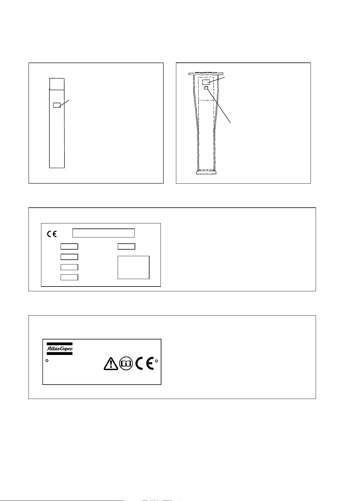
3CE markings EC machinery directive 98/37/EC
A Product group: Hydraulic breaker
(without guide system)
Location of CE sticker
3.1 CE sticker product groups A
B Product group: Hydraulic breaker with
breaker box
Location of CE sticker
LWA sticker
rear side of
breaker box,
below upper
flange
1
2
4
3
7
5
6
3.2 CE sticker product groups B
Atlas Copco Construction Tools
Essen Germany
Type
Ser. No.
Deliv. wt
P max
Year
Made in Germany
1. Name and address of manufacturer
2. Model
3. Serial no.
4. Part ident. no.
5. max. operating pressure
6. Year of construction of product group
7. Weight of product group
Name and address of manufacturer
Model
Serial no.
Weight of product group
max. operating pressure
Year of construction of product group
The CE nameplate contains information on the unit
"breaker and breaker box". All weights indicated refer
to the weight of this unit.
When selecting hoists and suspension aids for trans
porting the unit, the weights of the working tool and
adapter may also have to be considered.
10
In according with EC directives CE nameplates must
be affixed firmly and in a clearly visible position.
Should these nameplates be lost or defaced, repla
cements can be ordered from your dealer/from Chi
cago Pneumatic.
The following information must be provided:
Part ident. no. of the tool/ser. no. and date of delivery
(from the delivery note).

3.3 Sticker for guaranteed sound level power
In accordance with EU directive 2000/14/EC, hy
draulic breakers used within the EU must bear a
marking legible from the outside stating the sound
power level guaranteed by the manufacture.
4 General informations
4.1 Applications
The hydraulic breaker is an attachment suitable for
mounting on hydraulicpowered excavators.
The hydraulic breaker has been suited for the follow
ing operations:
Construction:
Demolition, tearing up, trenching, foundation work
4.2 Scope of supply
The scope of supply of a hydraulic breaker generally
includes:
Hydraulic breaker, operating instructions, spare parts
list and EC declaration of conformity.
Accessories: Mounting tool, hoses and service box
according to the order.
Special accessories: e. g. adapter, hydraulic adapter
kit for the excavator according to the order.
Mining and quarrying:
Primary breaking, bench leveling, reducing mineral
raw materials and rocks, tunnel construction
Under normal circumstances the hydraulic breaker is
operated from the driver’s cab of the carrier.
Please refer to Sections 2 and 6.5.
11
5 Main components
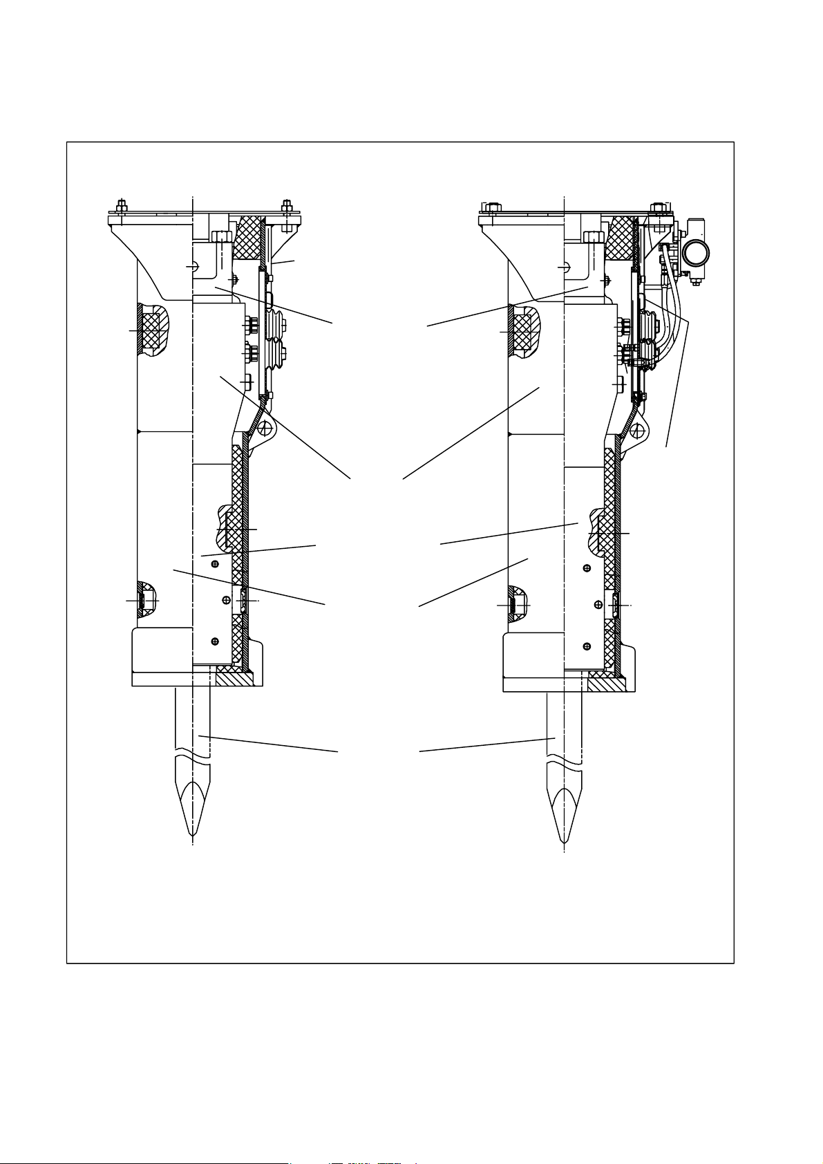
5.1 Main components or assemblies CP 550 and CP 750
CP 550 CP 750
CEnameplate
cylindercover
cylinder
CEname
plate
lower hammer part
hammerbox
working tool
The graphic shows only a general view of the main components.
Details may vary on different breaker models
12

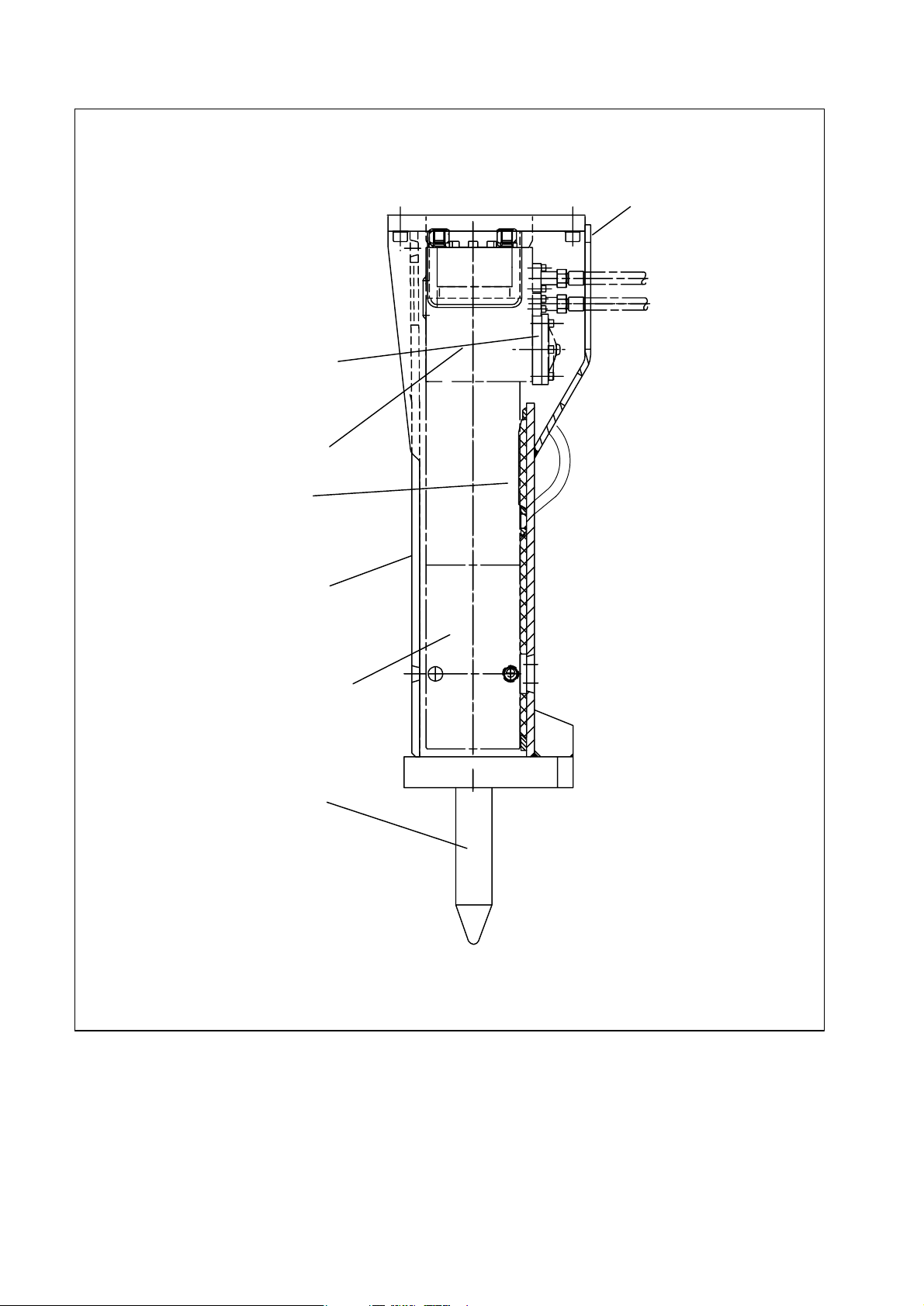
5.2 Main components or assemblies CP 1150 and CP 1650
CP 1150
CP 1650
CEname
plate
CEnameplate
cylinder cover
High−pressure
accumulator
cylinder
hammer box
lower hammer part
working tool
The graphic shows only a general view of the main components.
Details may vary on different breaker models.
13
5.3 Main components or assemblies, CP 2250, CP3050 and CP 4250
CP 2250,
CP 3050,
CP 4250
High−pressure
accumulator
cylinder cover
cylinder
CEname
plate
hammer box
Sealing flange
lower hammer part
working tool
The graphic shows only a general view of the main components.
Details may vary on different breaker models.
14
6 Installation
Â
Â
6.1 Media/consumables
The following media/consumables are required to operate the hydraulic breaker:
6.1.1 Mineral hydraulic oil
All hydraulic oil brands prescribed by the carrier
manufacturer are suitable for hydraulic breakers.
The oil should however correspond to viscosity class
HLP 32 or higher.
In summer and in hotter climates, oils of viscosity
class HLP 68 or higher should be used.
In all other respects the regulations of the carrier
manufacturer are to be considered.
Optimum viscosity range = 30 60 cSt
Max. initial viscosity = 2.000 cSt
Max. oil temperature = 80°C
Please refer to Section 9.12 for lowtemperature hy
draulic breaker applications.
Check the oil filter in the return line to the hydraulic
system.
6.1.2 Non−mineral hydraulic oil
In order to protect the environment or on technical
grounds, hydraulic oils are currently being used
which are not classified as HLP mineral oils.
Before using hydraulic oils of this kind it is imperative
to ask the carrier manufacturer whether operations
with such hydraulic oils are possible.
Our tools are basically designed for use with mineral
oils. Before using other hydraulic oil types which
have been approved by the carrier manufacturer,
Chicago Pneumatic Customer Center / dealer in your
region must always be consulted. Following initial
assembly and after any workshop repairs, our tools
are subjected to a test run on a test bed powered by
mineral oil.
The return line to the hydraulic system must be fittet
with an oil filter with a mesh no greater than 50
micrometers and equipped with a magnetic sparator.
CAUTION!
Monitor the oil temperature.
The temperature of the hydraulic oil must never ex
ceed 80°C. If higher temperatures are measured in
the tank, the hydraulic system and/or the pressure−
relief valve have to be checked.
CAUTION!
Never mix mineral and non−mineral hydraulic oils! Even
small traces of mineral oil mixed in with non−mineral hy
draulic oil can result in damage to both hydraulic attach
ment and carrier.
CAUTION!
Note
When returning tools for repair, it is imperative that
the name of the oil in use be indicated if you are
using non−mineral oil.
6.1.3 Grease
Grease type
ВВВВВВ
ВВВВВВВ
Chisel paste 3363 0949 10
Pt.−Id.−No.
Non−mineral oil is no longer biodegradable if it is con
taminated with mineral oil. Contaminated non−mineral
oil must be disposed of as special waste in accordance
with the applicable statutory regulations for environ
mental protection.
Always observe the relevant safety regulations when
handling oils and greases.
15
6.1.4 Gas
Normal nitrogen, 99.8% pure.
Use only nitrogen to fill the piston accumulator and
ensure that no other gas, e.g. air, oxygen, is used.
Risk of explosion!
The nitrogen for the piston accumulator is in the
green gas cylinder. Use of other gases could result in
an explosion.
DANGER!
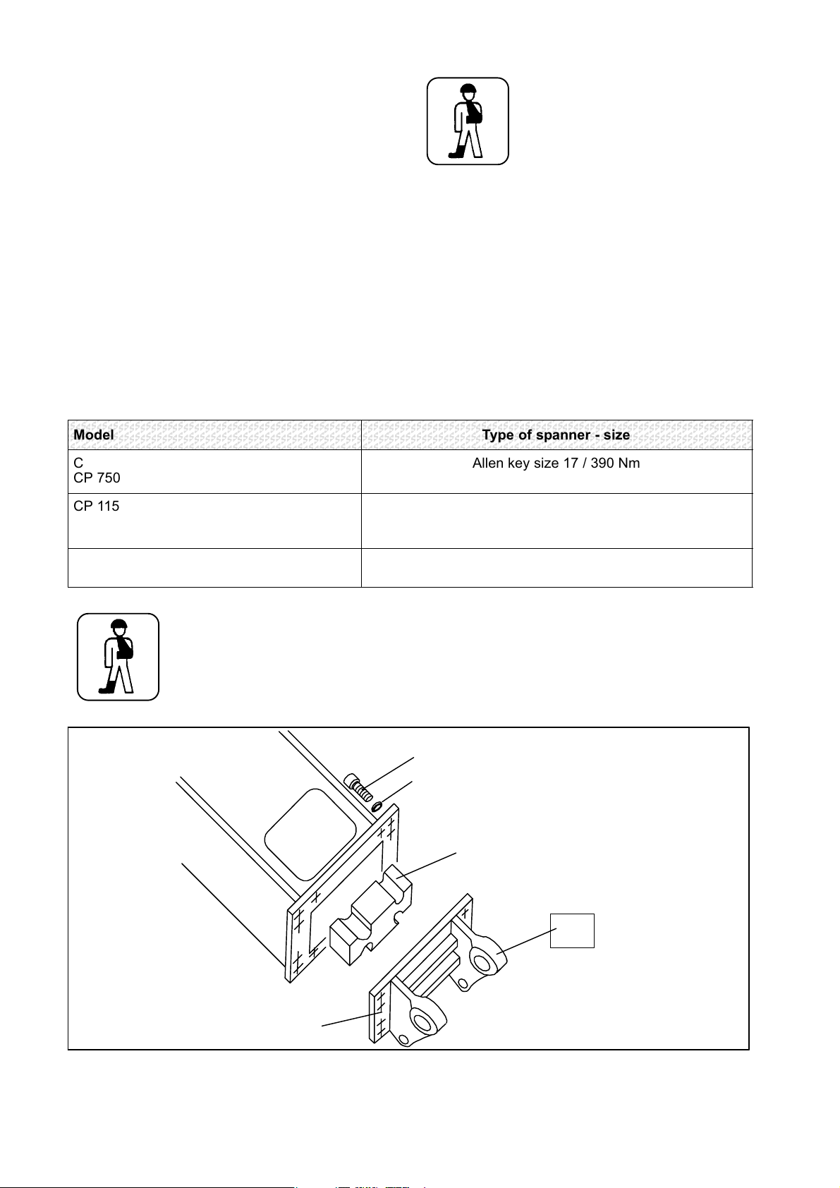
6.2 Attaching the adapter to the hydraulic breaker
Lay the hydraulic breaker on squared beams or a
pallet within reach of the excavator boom with the
service window of the breaker box facing upwards.
Insert the elastic pad in the breaker box, ensuring it
is the right way round, and fix the adapter to the
breaker box with two screws (referring to Sec
tion6.3)
Model
CP 550
CP 750
CP 1150
CP 1650
CP 2250
CP 3050
CP 4250
DANGER!
Then fit all screws. The required sizes for the Allen
keys are shown below.
Apply anti−seize to the threads of the cylindrical bolts
before screwing them in.
The contact face of the bolt head and the locking
rings must be free of lubricant.
Type of spanner − size
Allen key size 17 / 390 Nm
Allen key size 22 / 1500 Nm
Allen key size 27 / 2300 Nm
Only the specialsteel Allen screws included in sup
ply should be used to attach the adapter.
For transport purposes use only the lug(s) provided.
Note the weight (name plate, section 3.2).
16
Adapter
Screw
Pair of locking rings
Elastic pad
Marking:
Stiel
Stick
= Stiel
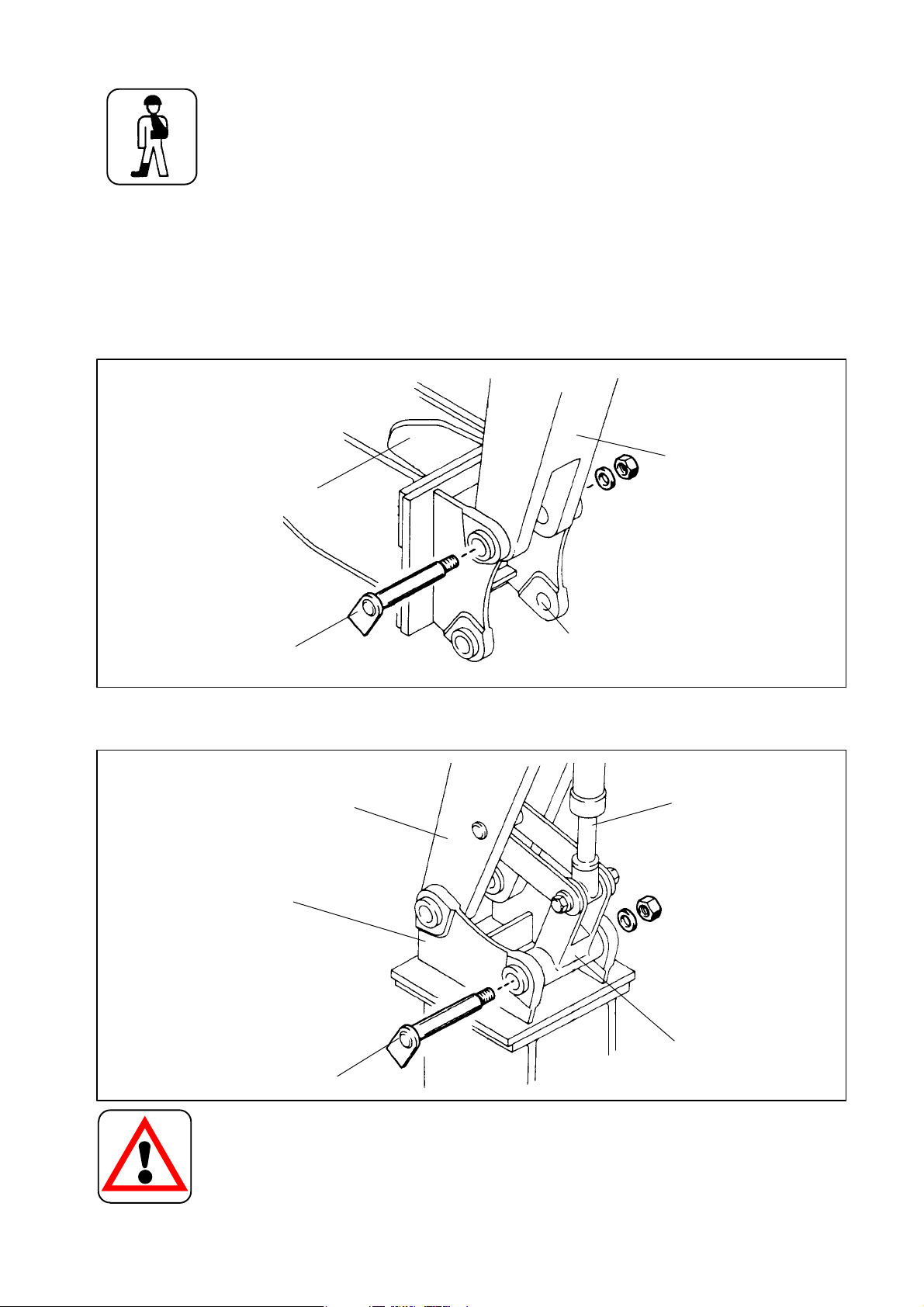
6.3 Mounting the hydraulic breaker on the excavatormechanical aspects
Keep your hands away from bores and fitting surfa
ces when mounting the hydraulic breaker.
DANGER!
Only mount the hydraulic breaker on an excavator
with sufficient load capacity. If the excavator is too
light it may become unstable and fall over.
During breaker mounting, the carrier should only be
operated from the driver’s cab.
Agree with the assistant on clear hand signals.
The assistant must be instructed by the excavator
driver.
Hydraulic breaker
Do not touch any parts when the boom is moving.
Never use your fingers to check whether the bores
are flush.
To mount the hydraulic breaker, carefully lower the
stick of the boom into the adapter. An assistant di
rects the movement of the stick until the bores in the
stick are flush with those in the adapter. Then insert
the stick pin and lock.
Stick
AdapterStick pin
Lift up the hydraulic breaker. Extend the shovel cylinder until the bore in the toggle is flush with those in the
adapter. Insert toggle pin and lock.
Stick
Adapter
Toggle pin
Shovel cylinder
Toggle
CAUTION!
After mounting the breaker, carefully extend and re
tract the shovel cylinder to its full extent in each
case. It is important that the cylinder can be fully ex
tended and retracted without any difficult. If problems
are encountered, please consult our Aftermarket de
partment.
17
 Loading...