


INSTALLATION INSTRUCTIONS
TAG: T-183 DATE: 5/97
RETROFIT MVP™
METERING CARTRIDGES
THIS INSTALLATION INSTRUCTION SHEET APPLIES TO
EXPOSED PARTS FOR CONVERSION OF EXISTING
LAVATORY FITTING TO MVP™ METERING VALVE
THIS FITTING HAS BEEN SET TO COMPLY WITH THE U.S.
NATIONAL ENERGY POLICY ACT (1992) WHICH REQUIRES
METERING FAUCETS TO FLOW .25 GALLONS PER CYCLE
MAXIMUM AT 80 PSI. PRODUCTS CONFORM TO APPLICABLE ADA REQUIREMENTS (SEE TIMING ADJUSTMENTS).
IMPORTANT:
1. Read instructions carefully before installation.
2. Be sure supply lines are thoroughly flushed before
installation.
3. Clean chrome only with mild soap and water - no cleansers
or acids.
U.S. PATENT NO. 4,899,778 and NO. 4,991,819
CANADIAN PATENT NO. 2005319
1
2
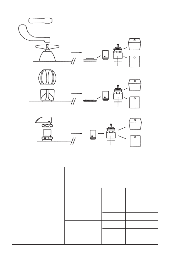
MOUNTING - FIT
RETROFIT FIT
(UNIT, ACTUATOR & HANDLE)
PART # 668-200K
ONE SET PER KIT
ONE SET PER KIT HANDLES INDEX KIT NO.
HOT 665 RKH
665 COLD 665 RKC
PUSH 665 RKP
HOT 669 RKH
669 COLD 669 RKC
PUSH 669 RKP
CHROME PLATED
FLANGE
#408-004 & RUBBER
WASHER #739-056.
THIS KIT IS REQUIRED
WHEN CONVERTING
TYPE I & II TO MVP
METERING UNITS.
TYPE I
WIDESPREAD
TYPE II
WIDESPREAD
TYPE III
WIDESPREAD
CENTERSETS
BASIN COCKS
VALVE WITH EXPOSED
CAP NUT
VALVE WITH
SKIRTED HANDLE
VALVE WITH ESCUTCHEON
REQUIRES
REQUIRES
REQUIRES
MOUNTING
KIT
MOUNTING
KIT
UNIT
UNIT
UNIT
ACTUATOR
ACTUATOR
ACTUATOR
HANDLES
HANDLES
HANDLES
TYPE 665
TYPE 669
TYPE 665
TYPE 669
TYPE 665
TYPE 669
OR
OR
OR
FIGURE 1
TO INSTALL:
1. Turn off water at the supply stop(s).
2. Remove existing handles and units. Follow the chart on the
first page (Figure 1 ) to insure that the correct parts are being
used.
3. Flush supply lines to remove chips and dirt which can
become lodged in the seat washer and cause the faucet to
run on.
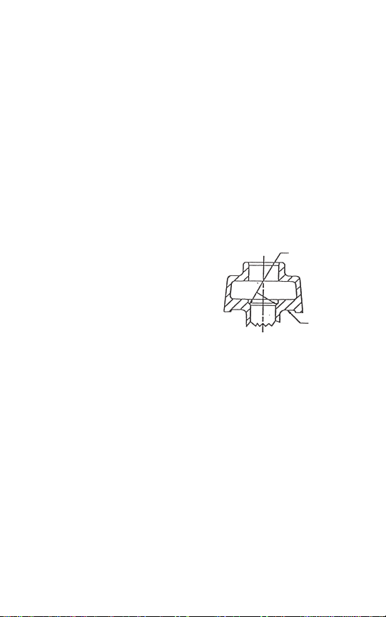
4. Inspect the seating surface inside the body and clean
thoroughly. If the seat is damaged (pitted or nicked) or if
heavy lime build-up has occurred, contact your nearest
Chicago Faucet representative for assistance. Failure to clean
up old seating surfaces can damage the new MVP™
cartridge and cause a dripping or
run-on situation. (Figure 2)
TROUBLE SHOOTING:
Accumulation of lime and/or dirt in
the cartridge can result in either short
or excessively long cycles. If either
occurs, remove cartridge and wash
with soap and water or a mild
solution of vinegar and water. If
continued problems are experienced,
contact your local representative for assistance.
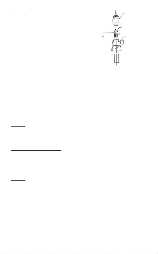
5. Insert the filter into the body and make sure it is completely
down and in place against the body seat. Then insert the
cartridge into the body. Make sure the cartridge is also
completely down and in place against the body seat
(Figure 3).
3
INSPECT
SEATING
AREA
TYPICAL
BODY
FIGURE 2
4
NOTE:
This cartridge is designed to be
used with the large filter enclosed. It is
possible when retrofitting existing fittings
that this filter cannot be used (especially
in type I and II fittings shown on Page
2). If no water flow occurs after Step
7, shut the stop off and disassemble
fitting to remove the larger drop-in style
filter. Replace it as shown with the small
filter enclosed.
IMPORTANT: NEVER USE BOTH FILTERS TOGETHER ON
THE SAME FITTING
6. Place the white cap sealing gasket into the actuator
assembly and screw the actuator assembly onto the body.
Tighten the actuator assembly onto the body to
approximately 20 ft. Ibs., (Hand tighten and give the actuator
assembly a 1/2 to 1 full turn with a wrench). (Figure 3)
7. Turn the water back on at the supply stop(s).
NOTE:
If leak occurs at cap gasket, remove gasket and inspect
it for damage and replace it if necessary. If the gasket is in good
condition, inspect the body surface for scratches or nicks and
clean up the surface by reaming if necessary.
TIMING ADJUSTMENT
:
These instructions are for the user to adjust the faucet to provide
a flow rate to meet the American Disability Act (ADA) regulations
which require 10 seconds running time for the water flow. For
ADA compliance follow these procedures:
NOTE:
Timing must be checked with the handle in place.
A) Purge the valve of air by pushing it completely open 4-8
times rapidly and then check the timing cycle .
B) Remove the handle with a 3/32” hex wrench.
ACTUATOR
ASSEMBLY
GASKET
CARTRIDGE
FILTER
TYPICAL BODY
OPTIONAL
(SEE NOTE)
FIGURE 3
5
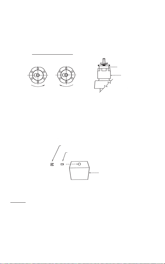
E) Once cycle time is satisfactory, lock handle in place making
sure set screw is securely fastened on groove in stem.
(Figure 5) If a type 665 handle is used, remember to insert the
colored index button.
NOTE: A variation from cycle to cycle should be expected. It is
best to wait until hot water is available and the building as in use
before making final adjustments.
Some new installations may produce a slight closing noise. This
is normally the result of air trapped in the unit and the noise will
dissipate over time.
BUTTON
SET SCREW
665 HANDLE
FIGURE 5
DECREASE
TIME
INCREASE
TIME
FIGURE 4
HOW TO ADJUST
TOP VIEW
ADJUSTING NUT
ACTUATOR
C) Time is changed by rotating plastic serrated adjustment nut
with a pair of pliers. Raising nut (counter clockwise) shortens
time, lowering nut (clockwise) lengthens time.
(Figure 4)
D) After each adjustment, replace handle and check cycle time.

6
INSTRUCCIONES DE INSTALACION
ETIQUETA: T-183 FECHA: 5/97
CARTUCHOS DE MEDICION
DE MODIFICACION
RETROACTIVA MVP™
ESTE PLIEGO CON INSTRUCCIONES DE INSTALACION ES VALIDO
PARA LAS PIEZAS EXPUESTAS CON LA FINALIDAD DE EFECTUAR
LA CONVERSION DEL ACCESORIO EXISTENTE DE LAVABO A LA
VALVULA DE MEDICION MVP™
ESTE ACCESORIO HA SIDO AJUSTADO PARA CUMPLIR CON LA
LEY DE POLITICA ENERGETICA NACIONAL DE 1992 (NATIONAL
ENERGY POLICY ACT, 1992) QUE EXIGE QUE EL AGUA DE LOS
GRIFOS DE MEDICION FLUYA UN CUARTO DE GALON (0.94 LITRO)
POR CICLO MAXIMO A UNA PRESION DE 550 KPa (KILOPASCALS).
LOS PRODUCTOS CUMPLEN CON LOS REQUISITOS
CORRESPONDIENTES DE LA LEY DE CIUDADANOS INCAPACITADOS
(AMERICAN DISABILITY ACT, ADA) (VER LA SECCION "AJUSTE DE LA
TEMPORIZACION").
IMPORTANTE:
1. Lea cuidadosamente las instrucciones antes de la
instalación.
2. Asegúrese de que las tuberías de suministro sean lavadas
minuciosamente con abundancia de agua antes de la
instalación.
3. Limpie las piezas cromadas solamente con jabón suave y
agua - nunca con productos limpiadores o ácidos.
PATENTE ESTADOUNIDENSE No. 4.899.778 y No. 4.991.819
PATENTE CANADIENSE No. 2005319

7
KIT DE MONTAJE
KIT DE MODIFICACION RETROACTIVA
(UNIDAD, ACCIONADOR Y MANGO)
PIEZA # 668-200K
UN JUEGO POR CADA KIT
UN JUEGO POR MANGOS POSICIONADOR KIT No.
CADA KIT
CALIENTE
665 RKH
665 FRIO 665 RKC
EMPUJE 665 RKP
CALIENTE 669 RKH
669 FRIO 669 RKC
EMPUJE 669 RKP
REBORDE CROMADO
#408-004 & ARANDELA
DE CAUCHO #739-056.
ESTE KIT ES
NECESARIO CUANDO
SE CONVIERTEN
UNIDADES DEL TIPO I
& II EN UNIDADES DE
MEDICION MVP.
TIPO I
EXTENDIDO
TIPO II
EXTENDIDO
TIPO III LLAVES
EXTENDIDAS DE
PILETA CON
CENTROS
VALVULA CON
TUERCA TAPA
EXPUESTA
VALVULA CON MANGO
RIBETEADO
VALVULA CON ESCUDETE
REQUIERE
REQUIERE
REQUIERE
KIT DE
MONTAJE
KIT DE
MONTAJE
UNIDAD
UNIDAD
UNIDAD
ACCIONADOR
ACCIONADOR
ACCIONADOR
MANGOS
MANGOS
MANGOS
TIPO 665
TIPO 669
TIPO 665
TIPO 669
TIPO 665
TIPO 669
O
O
O
FIGURA 1

8
PARA INSTALAR:
1. Cierre el flujo de agua en la(s) llave(s) de paso del suministro.
2. Saque los mangos y las unidades existentes. Siga las indicaciones del
cuadro en la primera página (Figura 1) para asegurar que se estén
usando las piezas correctas.
3. Lave las tuberías de suministro con agua en abundancia para remover
los residuos y el sucio que puedan haberse alojado en la arandela del
asiento y que pueden hacer que el grifo bote agua continuamente.
4. Inspeccione la superficie de asentamiento dentro del cuerpo de la
válvula y límpiela minuciosamente. Si el asiento está dañado (corroído
o mellado) o si ha ocurrido una pesada acumulación de cal, póngase
en contacto con el representante de Chicago Faucet más cercano
para obtener asistencia. Si no se limpian completamente las viejas
superficies de asentamiento, es posible que se dañe el nuevo
cartucho MVP™ y se produzca una
situación de goteo o pérdida constante
de agua. (Figura 2)
CORRECCIÓN DE FALLAS:
La acumulación de cal y/o sucio en el
cartucho puede ocasionar ciclos cortos o
ciclos excesivamente largos. Si ocurre uno
de estos problemas en los ciclos, saque el
cartucho y lávelo con agua y jabón o una
solución suave de vinagre y agua. Si sigue
teniendo problemas continuamente, póngase en contacto con el
representante local de Chicago Faucet para obtener asistencia.
5. Inserte el filtro dentro del cuerpo y asegúrese de que el filtro esté
completamente abajo y en su sitio contra el asiento del cuerpo.
Seguidamente inserte el cartucho dentro del cuerpo. Asegúrese de
que el cartucho también esté
completamente abajo y en su sitio contra
el asiento del cuerpo (Figura 3).
NOT
A: Este cartucho está diseñado para ser
usado con el filtro grande que viene con la
unidad. Al retroadaptar los accesorios
existentes, es posible que no se pueda
usar este filtro (especialmente en los
accesorios del tipo I y del tipo II que se
muestran en la página 2). Si el agua no fluye
luego de completar el Paso 7, cierre la llave
de paso y desarme el accesorio para sacar
REVISE EL
AREA DEL
ASIENTO
CUERPO
TIPICO
FIGURA 2
CONJUNTO DEL
ACCIONADOR
EMPAQUETADURA
CARTUCHO
FILTRO
CUERPO TIPICO
OPCIONAL
(VER NOTA)
FIGURA 3

9
el filtro de mayor tamaño de estilo embutido. Reemplácelo como se
muestra con el filtro pequeño que viene con la unidad.
IMPORTANTE: NUNCA USE AMBOS FILTROS JUNTOS
EN EL MISMO ACCESORIO
6. Coloque la empaquetadura sellante de tapa blanca dentro del
conjunto del accionador y atornille el conjunto del accionador en el
cuerpo. Apriete el conjunto del accionador en el cuerpo a
aproximadamente 20 pies/libra (2.7 kilográmetros). (Apriete a mano y
déle al conjunto del accionador de media vuelta a una vuelta
completa con una llave.) (Figura 3)
7. Abra otra vez la(s) llave(s) de paso del suministro.
NOT
A: Si ocurre una fuga de agua en la empaquetadura de tapa, saque
la empaquetadura y revísela para detectar daños y reemplácela, de ser
necesario. Si la empaquetadura está en buen estado, revise la superficie
del cuerpo para detectar arañazos o mellas y limpie la superficie
escariándola, de ser necesario.
AJUSTE DE LA TEMPORIZACION:
El tiempo del ciclo viene
preajustado de la fábrica. Estas instrucciones tienen la finalidad de que el
usuario ajuste el grifo de tal manera que éste suministre un caudal de
agua que cumpla con las disposiciones reglamentarias de la Ley de
ciudadanos incapacitados (American Disability Act, ADA) que exigen un
tiempo de servicio (10) para el flujo de agua. Para cumplir con los
requisitos de la ADA, siga estos procedimientos:
NOT
A: La temporización debe revisarse con el mango en su lugar.
A) Elimine el aire que pueda haber en la válvula abriéndola
completamente 4-8 veces con rapidez y comprobando seguidamente
el ciclo de temporización.
B) Saque el mango con una llave hexagonal de 3/32”.
C) El tiempo se cambia girando la tuerca dentada plástica de ajuste de
color blanco con unas tenazas. Levantando la tuerca (haciéndola girar
en el sentido de rotación contrario al de las manecillas del reloj) se
acorta el tiempo; bajando la tuerca (haciéndola girar en el sentido de
las manecillas del reloj) se alarga el tiempo. (Figura 4)

10
D) Después de cada ajuste, vuelva a colocar el mango y compruebe el
tiempo del ciclo.
E) Una vez que el tiempo del ciclo sea satisfactorio, trabe el mango en
su sitio asegurándose de que el tornillo prisionero esté fijado
firmemente en la muesca en el vástago. (Figura 5) Si se usa un mango
de tipo 665, recuerde insertar el botón de posicionamiento de color.
NOTA: Cabe esperar que ocurra una variación de ciclo a ciclo. Es mejor
aguardar hasta que haya agua caliente disponible y el edificio esté
ocupado antes de efectuar los ajustes finales.
Algunas instalaciones nuevas pueden producir un ligero ruido al cerrar.
Esto es causado normalmente por el aire que quedó atrapado en la
unidad y este ruido desaparecerá con el paso del tiempo.
BOTON
TORNILLO PRISIONERO
MANGO 665
FIGURA 5
DISMINUIR
EL TIEMPO
AUMENTAR
EL TIEMPO
FIGURA 4
COMO AJUSTAR EL TIEMPO
VISTO DESDE ARRIBA
TUERCA DE
ACCIONADOR

INSTRUCTIONS D'INSTALLATION
NUMÉRO: T-183 DATE: 5/97
CARTOUCHES À AUTO-
FERMETURE MPV POUR
CONVERSION
LES INSTRUCTIONS D'INSTALLATION CI-APRÈS
S'APPLIQUENT À LA CONVERSION D'UNE ROBINETTERIE
DE LAVABO DÉJÀ EN PLACE AU
MOYEN D'UNE CARTOUCHE MVP™.
CETTE CARTOUCHE EST CONFORME À LA NATIONAL
ENERGY POLICY ACT (LOI AMÉRICAINE SUR LES
ÉCONOMIES D'ÉNERGIE) DE 1992, QUI STIPULE QUE LES
ROBINETS DOIVENT DÉBITER AU MAXIMUM 0,25 GALLON
PAR CYCLE À UNE PRESSION DE 550 KPa (KILOPASCALS).
CE PRODUIT EST CONFORME AUX EXIGENCES PERTINENTES DE L'AMERICAN DISABILITY ACT (LOI AMÉRI-CAINE
SUR LES INSTALLATIONS POUR PERSONNES HANDICAPÉES); VOIR LE RÉGLAGE DE DURÉE D'ÉCOULEMENT.
IMPORTANT:
1. Lire attentivement les instructions avant de procéder à
l'installation.
2. Rincer à fond toute la tuyauterie d'arrivée d'eau avant de
procéder à l'installation.
3. Utiliser uniquement un savon doux et de l'eau pour nettoyer
les surfaces chromées; ne pas utiliser de produits de
récurage ou d'acides.
BREVETS U.S Nos 4,899,778 ET 4,991,819
BREVET CANADIEN No 2005319
11

12
NÉCESSAIRE Nécessaire de conversion
DE MONTAGE (cartouche, actionneur et manette)
No CAT. 668-200K UN JEU PAR NÉCESSAIRE
Manettes Marquage No de catalogue
CHAUD 665 RKH
665 FROID 665 RKC
POUSSER 665 RKP
CHAUD 669 RKH
669 FROID 669 RKC
POUSSER 669 RKP
UN JEU PAR NÉCESSAIRE
BRIDE CHROMÉE
No 408-004
ET RONDELLE DE
CAOUTCHOUC No 739-056
CE NÉCESSAIRE EST
REQUIS POUR CONVERTIR
LES ROBINETS DE TYPE I
ET II EN ROBINETS À
AUTO-FERMETURE MVP.
ROBINETTERIE
DE TYPE I
GRANDE
LARGEUR
ROBINETTERIE
DE TYPE II
GRANDE
LARGEUR
ROBINETTERIE
DE TYPE III
GRANDE
LARGEUR À
MONTAGE
CENTRAL,
POUR LAVABO
ROBINET À
ÉCROU-CHAPEAU À
DÉCOUVERT
ROBINET AVEC
MANETTE À JUPE
ROBINET À ROSACE
ÉLÉMENTS
REQUIS:
ÉLÉMENTS
REQUIS:
ÉLÉMENTS
REQUIS:
NÉCESSAIRE
DE MONTAGE
NÉCESSAIRE
DE MONTAGE
CARTOUCHE
CARTOUCHE
CARTOUCHE
ACTIONNEUR
ACTIONNEUR
ACTIONNEUR
MANETTES
MANETTES
MANETTES
TYPE 665
TYPE 669
TYPE 665
TYPE 669
TYPE 665
TYPE 669
OU
OU
OU
FIGURE 1

POUR INSTALLER:
1. Fermer les robinets d'arrivée d'eau.
2. Enlever les manettes et autres pièces internes. Consulter le
tableau de la première page (Figure 1) pour être certain d'utiliser
les bonnes pièces.
3. Rincer la tuyauterie afin de chasser les débris et autres saletés
qui pourraient venir se loger sur le siège du robinet et l'empêcher
de bien fermer.
4. Examiner la surface d’assise à l'intérieur du corps de robinet et
la nettoyer méticuleusement. Si l’assise s’avère endommagée
(piqûres ou écailles), ou si elle présente une accumulation
excessive de calcaire, contacter le représentant Chicago Faucet
le plus proche pour lui demander son aide. Une assise
encrassée peut endommager la nouvelle cartouche MVP™ et
provoquer une fuite ou empêcher
la fermeture du robinet (Figure 2).
DEPANNAGE:
Toute accumulation de calcaire et/ou
de saletés dans la cartouche peut
écourter les cycles ou les prolonger
de façon excessive. Dans l’un et
l’autre cas, retirer la cartouche et la
laver a l’eau savonneuse, ou
additionnée d’une petite quantité de vinaigre. Si le problème
persiste, demander l’aide du représentant le plus proche.
5. Insérer bien à fond le filtre dans le
robinet; s'assurer qu'il est bien
appuyé sur le siège. Ensuite,
introduire la cartouche dans le
robinet; elle aussi doit être bien
appuyée sur le siège du robinet
(Figure 3).
Verifier la
surface
du siege
Corps de
robinet
(représentatif)
FIGURE 2
Actionneur
Joint d'étanchéité
Cartouche
Filtre
Corps de robinet
(représentatif)
Facultatif
(Voir la
remarque)
FIGURE 3
13

14
NOTE: Normalement, on utilise le plus grand des deux filtres fournis
avec la cartouche. Toutefois, dans le cas de certains robinets (surtout
de types I et II, voir page 2), il est possible que le grand filtre ne soit
pas utilisable. Si l'eau ne coule pas après l'étape 7, fermer les
robinets d'arrêt et démonter le robinet; retirer le grand filtre et le
remplacer par le petit filtre (Figure 3).
IMPORTANT: NE JAMAIS UTILISER LES DEUX FILTRES DANS LE
MÊME ROBINET.
6. Insérer le joint de chapeau blanc dans l'actionneur, puis visser
l'actionneur dans le robinet. Serrer l'actionneur à environ 20 lb-pi
(serrer d'abord à la main, puis visser de 1/2 à 1 tour à l'aide d'une
clé) (Figure 3).
7. Rétablir l'arrivée d'eau en ouvrant les robinets d'arrêt.
NOTE:
S'il y a une fuite au joint de chapeau, enlever le joint pour voir
s'il est endommagé et le remplacer si nécessaire. Si le joint est en
bon état, vérifier si la portée du corps du robinet est rayée ou
entaillée; rectifier la surface au besoin.
RÉGLAGE DE LA DURÉE D'ÉCOULEMENT
: La durée d'écoulement
est préréglée à l'usine. Les instructions suivantes permettent à
l'utilisateur d'obtenir une durée d'écoulement conforme à l'American
Disability Act (Loi américaine sur les installations pour personnes
handicapées), qui prescrit un écoulement de 10 secondes.
NOTE:
La manette doit être en place lorsqu'on vérifie la durée
d'écoulement.
A) Purger l'air de la cartouche en l'enfonçant complètement à
plusieurs reprises (de 4 à 8 fois). Vérifier ensuite le cycle
d'écoulement.
B) Enlever la manette à l'aide d'une clé hexagonal 3/32 po.
C) Pour modifier la durée d'écoulement, tourner l'écrou moleté de
réglage en plastique à l'aide d'une pince. En desserrant l'écrou
(sens anti-horaire), on réduit la durée d'écoulement; en serrant
l'écrou (sens horaire), on augmente la durée d'écoulement
(Figure 4).

15
D) Après chaque réglage, remettre la manette en place et vérifier la
durée d'écoulement.
E) Lorsque le réglage est satisfaisant, bloquer la manette en serrant
bien la vis de pression dans la rainure de la tige du robinet (Figure
5). Dans le cas d'une manette de type 665, ne pas oublier de
poser la coiffe indicatrice colorée.
NOTE: Des variations d'un cycle à l'autre sont possibles. Il est
préférable d'effectuer les derniers réglages lorsque l'eau chaude est
disponible et que le bâtiment est en service.
Un appareil neuf peut émettre un léger bruit à la fermeture, à cause
de l'air piégé dans la cartouche; ce bruit disparaîtra avec le temps.
COIFFE
VIS DE PRESSION
MANETTE 665
FIGURE 5
Pour diminuer
la durée
Pour augmenter
la durée
FIGURE 4
Réglage de durée d'écoulement -
Vue de dessus
Écrou de réglage
Actionneur

 Loading...