

Chicago Faucet 897 Installation Manual
INSTALLATION INSTRUCTIONS FOR
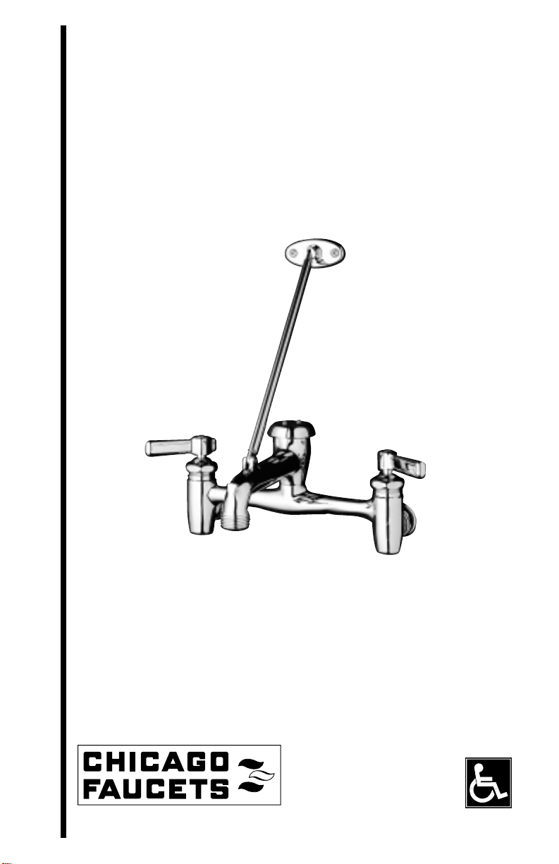
897 SERVICE SINK FAUCET
INSTRUCCIONES PARA LA INSTALACIÓN DEL
GRIFO 897 PARA FREGADERO DE SERVICIO
DIRECTIVES DE POSE DU ROBINET
MÉLANGEUR DE POSTE D’EAU 897
Last As Long As the Building
INSTALLATION SHOULD BE IN ACCORDANCE WITH LOCAL PLUMBING
CODES. FLUSH ALL PIPES THOROUGHLY BEFORE INSTALLATION.
LA INSTALACIÓN DEBE EFECTUARSE EN CONFORMIDAD CON LOS
CÓDIGOS LOCALES DE PLOMERÍA. LAVE CON ABUNDANCIA DE AGUA
TODAS LAS TUBERÍAS ANTES DE LA INSTALACIÓN.
L'INSTALLATION DOIT ÊTRE CONFORME AUX CODES LOCAUX EN
MATIÈRE DE PLOMBERIE PURGER SOIGNEUSEMENT TOUS LES TUYAUX
AVANT L'INSTALLATION.
ADA Compliant

INDEX
897 Service Sink Faucet . . . . . . . . . . . . . . . . . . . . . . . . . . . . . . . . . . . . . . . . . . . . . . . . . . . . . . . . . . 3
“Quaturn”Cartridges . . . . . . . . . . . . . . . . . . . . . . . . . . . . . . . . . . . . . . . . . . . . . . . . . . . . . . . . . . . . . 7
Care and Maintenance . . . . . . . . . . . . . . . . . . . . . . . . . . . . . . . . . . . . . . . . . . . . . . . . . . . . . . . . . . . 9
Notes . . . . . . . . . . . . . . . . . . . . . . . . . . . . . . . . . . . . . . . . . . . . . . . . . . . . . . . . . . . . . . . . . . . . . 10-11
ÍNDICE
Grifo 897 Para Fregadero de Servicio . . . . . . . . . . . . . . . . . . . . . . . . . . . . . . . . . . . . . . . . . . . . . . . . 4
Cartuchos “Quaturn” . . . . . . . . . . . . . . . . . . . . . . . . . . . . . . . . . . . . . . . . . . . . . . . . . . . . . . . . . . . . 7
Cuidado y Mantenimiento . . . . . . . . . . . . . . . . . . . . . . . . . . . . . . . . . . . . . . . . . . . . . . . . . . . . . . . . . 9
Notas . . . . . . . . . . . . . . . . . . . . . . . . . . . . . . . . . . . . . . . . . . . . . . . . . . . . . . . . . . . . . . . . . . . . . 10-11
INDEX
Robinet Mélangeur de Poste D’eau 897 . . . . . . . . . . . . . . . . . . . . . . . . . . . . . . . . . . . . . . . . . . . . . . 5
Cartouches “Quaturn” . . . . . . . . . . . . . . . . . . . . . . . . . . . . . . . . . . . . . . . . . . . . . . . . . . . . . . . . . . . . 8
Entretien . . . . . . . . . . . . . . . . . . . . . . . . . . . . . . . . . . . . . . . . . . . . . . . . . . . . . . . . . . . . . . . . . . . . . . 9
Notes . . . . . . . . . . . . . . . . . . . . . . . . . . . . . . . . . . . . . . . . . . . . . . . . . . . . . . . . . . . . . . . . . . . . . 10-11

3
897 Service Sink
INSTALLATION INSTRUCTIONS
REFER TO PAGE 6 FOR ILLUSTRATION.
1. Water supplies must be shut off. Supply lines must have 1/2" NPT male threaded ends and
should protrude 5/8" – 7/8" from the finished wall on 8" centers. Supply lines must be secured to
support the faucet.
2. Apply pipe sealant to the 1/2" NPT threads of the supply lines.
3. Remove supply arms from faucet and screw onto supply lines. (See Fig. 1) Position the supply
arms so they line up with the faucet inlets (8" center to center).
NOTE: The faucet must be mounted level, adjust supply arms as necessary.
4. Place the flanges over the supply arms and against the finished wall. (See Fig. 1)
5. Make sure inlet gasket is sitting in place within the union nut. (See Fig. 1) Attach faucet to supply
arms and tighten union nut securely.
6. Remove the set screw from the brace rod. Place the brace rod in the slot on the spout and
reattach the set screw using 3/32" hex key wrench. (See Fig. 2)
7. Place brace flange against the finished wall and center it with the spout. Secure the flange to the
wall using (2) wood screws provided.
NOTE: Finished wall must be supported where the brace flange mounts to the wall to provide
maximum support.
8. Turn on water supply and check supply lines and faucet connections for leaks.
SERVICE INSTRUCTIONS
1. The faucet is furnished with integral supply stops. To shut off water supply, screw stops in using
5/16" hex key wrench until water is shut off. Open the supply stop no more than three (3)
complete turns.
NOTE: Stop can unscrew completely causing water to spray out from the stop opening.
2. For adjustment of cartridges, refer to page 7.

4
Grifo 897 Para Fregadero de Servicio
INSTRUCCIONES PARA LA INSTALACIÓN
EN LA PAGINA 6 HALLARÁ LA ILUSTRACIÓN.
1. Asegure que el suministro ha sido interrumpido / cerrado. Las líneas de suministro de agua
tienen que tener una rosca de cabo macho de 1/2" NPT (12.7 mm) y tiene que sobresalir
5/8"–7/8" (15.87 mm – 22.2 mm) desde la pared acabada en centros de 8" (203 mm). Las líneas
de suministro de agua tienen que estar aseguradas para sostener el grifo.
2. Aplique sellador de cañerías en la rosca de 1.2" NTP (12.7 mm) de las líneas de suministro de
agua.
3. Quite los tubos de suministro de agua desde el grifo y sujete con los tornillos en las líneas de
suministro de agua. (Vea la figura 1) Coloque los tubos de suministro de agua de manera que
estén alineados con los agujeros de entrada del grifo (8" [203 mm] centro a centro).
NOTA: El grifo tiene que estar montado en nivel, por favor ajuste los tubos de suministro de
agua si es necesario.
4. Instale el reborde conector sobre los tubos de suministro de agua y contra la pared acabada.
(Vea la figura 1)
5. Asegure que el empaque de entrada está asentado en su lugar dentro de la tuerca de unión.
((Vea la figura 1) Conecte el grifo a los tubos de suministro de agua y apriete firmemente la
tuerca de unión.
6. Quite el tornillo de ajustamiento desde la varilla abrazadera. Ponga la varilla abrazadera en la
ranura del surtidor y vuelva a conectar los tornillos de ajustamiento usando la llave de 3/32"
(1.59 mm) para tuercas Hex. (Vea la figura 2)
7. Ponga el reborde conector de la abrazadera contra la pared acabada y en el centro con el
surtidor. Asegure el reborde conector en la pared usando los dos (2) tornillos suministrados.
NOTA: La pared acabada tiene que estar soportada donde el reborde conector se monta con la
pared para proveer un soporte máximo.
8. Abra la llave de paso del suministro de agua y compruebe las líneas de suministro y el grifo
para detectar si existe alguna fuga.
INSTRUCCIONES PARA EL SERVICIO
1. El grifo viene con interruptores de paso del suministro integrales. Para interrumpir el suministro
del agua, en tornille los interruptores usando un llave tipo Hex de 5/16"(7.94 mm) hasta que el
suministro de agua es interrumpido. Abra el interruptor de suministro de agua no más que tres
(3) vueltas completas.
NOTA: Los interruptores de suministro de agua pueden ser destornillados completamente
causando que el agua salga desde la abertura del interruptor.
2. Para ajustar los cartuchos, refiérase a las páginas 7.
 Loading...