

Chicago Faucet 242.659.00.1 Installation Manual
Installation Instructions
Bank Installation
for Plug-in Transformer
Model No. 242.559.00.1
The Chicago Faucets plug-in transformer may be used with HyTronic® and E-Tronic® 40 models.
Each transformer can provide power for up to eight faucets.
Installation
1. At each faucet, connect the AC connector from the
faucet to the bank installation adapter. See Figure 1.
NOTE 1: The Bank Installation Adapter Wire is
included with all HyTronic AC faucet models. If you
are installing an E-Tronic 40 model, you will need to
purchase the Bank Installation Adapter Wire separately
(part no. 242.340.00.1).
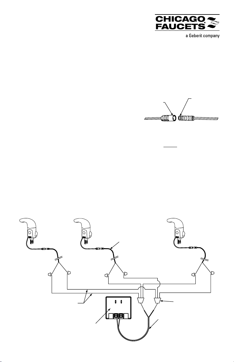
2. Route the AC adapter cables from each faucet to a common location near an electrical outlet.
3. Twist the stripped ends of the black wires together. Twist the stripped ends of the red wires
together. ALL FAUCETS MUST BE CONNECTED IN PARALLEL. Do not attempt to daisy-
chain the AC connectors.
NOTE 2: If powering multiple faucets, you may need to provide a wiring pigtail, additional wire, and
wire nuts to connect the twisted wires to the terminals on the transformer. See Figure 2.
4. Loosen the terminal screws on the transformer, route the twisted wires under the screws, and
tighten the screws securely to hold the twisted wires in place. Please note that the polarity of the
connection is not important; the black and red wires may be attached to either terminal.
5. Plug the transformer into an AC outlet and confirm that each faucet is operational.
Figure 2. Example Wiring Diagram
Three faucets shown. Plug-in transformer may be used with up to eight faucets.
Figure 1. Connecting Bank
Installation Adapter (see Note 1)
AC Connector
From Faucet
Adapter Wire
(242.340.00.1)
Additional wiring supplied
by installer (if needed) –
18 AWG recommended
Plug-in Transformer
(242.559.00.1)
Bank Installation
Adapter Wire
(242.340.00.1)
Wire nuts supplied
by installer (if needed)
Wiring pigtail supplied
by installer (if needed) –
16 AWG recommended
Installation Instructions
Bank Installation
for Hard-wired Transformer
Model No. 242.659.00.1
The Chicago Faucets hard-wired transformer may be used with HyTronic® and E-Tronic® 40 models.
Each transformer can provide power for up to eight faucets.
Installation
The transformer should be mounted to an approved
electrical box, following local electrical codes. Switch
off the power to the transformer before completing the
electrical connections.
1. At each faucet, connect the AC connector from the
faucet to the bank installation adapter. See Figure 1.
NOTE 1: The Bank Installation Adapter Wire is included with all HyTronic AC faucet models. If you
are installing an E-Tronic 40 model, you will need to purchase the Bank Installation Adapter Wire
separately (part no. 242.340.00.1).
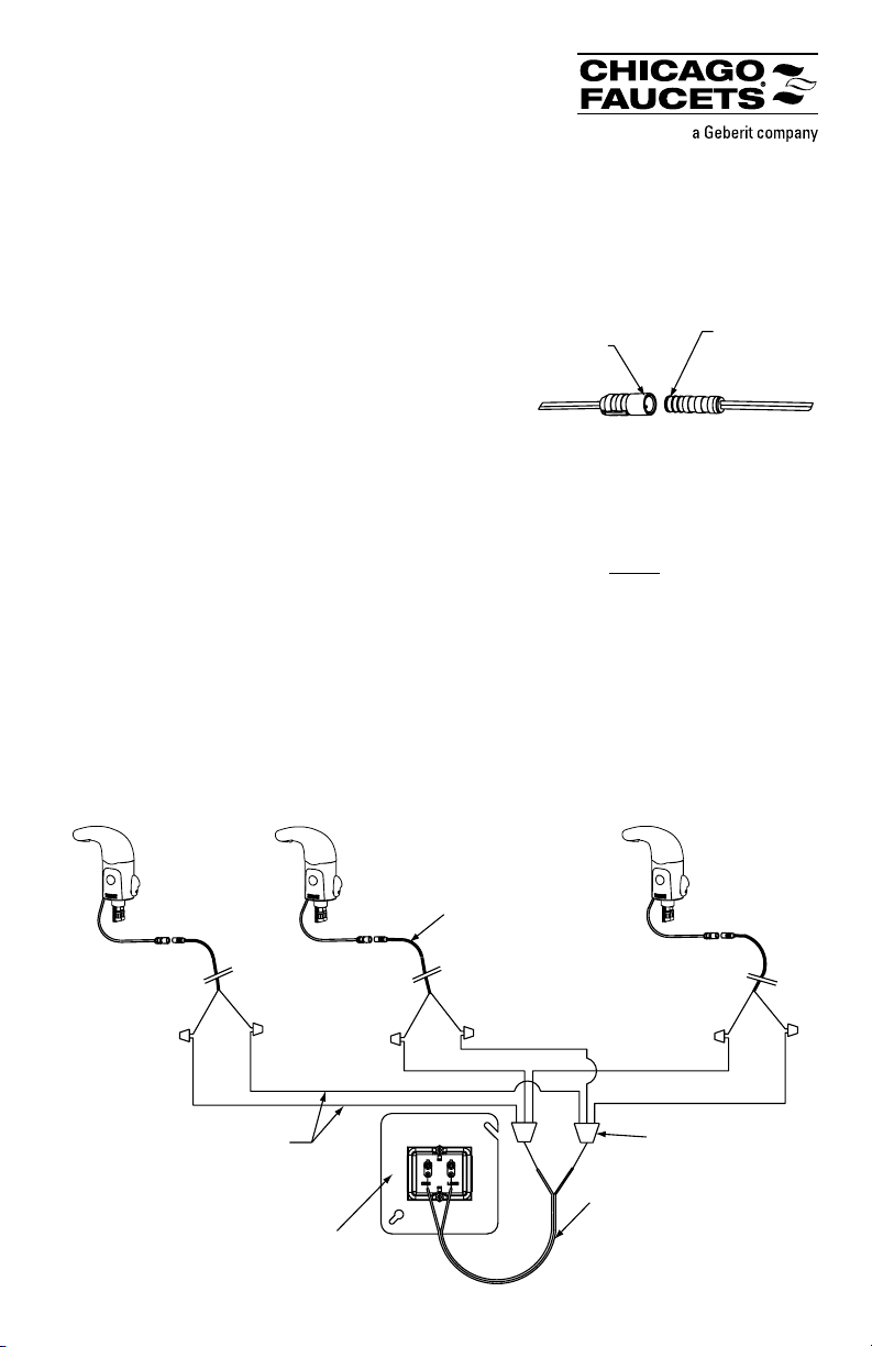
2. Route the AC adapter cables from each faucet to the transformer.
3. Twist the stripped ends of the black wires together. Twist the stripped ends of the red wires
together. ALL FAUCETS MUST BE CONNECTED IN PARALLEL. Do not attempt to daisy-
chain the electrical connections.
NOTE 2: If powering multiple faucets, you may need to provide a wiring pigtail, additional wire, and
wire nuts to connect the twisted wires to the terminals on the transformer. See Figure 2.
4. Loosen the terminal screws on the transformer, route the twisted wires under the screws, and
tighten the screws securely to hold the twisted wires in place. Please note that the polarity of the
connection is not important; the black and red wires may be attached to either terminal.
5. Turn on the power to the transformer and confirm that each faucet is operational.
Figure 2. Example Wiring Diagram
Three faucets shown. Hard-wired transformer may be used with up to eight faucets.
Figure 1. Connecting Bank
Installation Adapter (see Note 1)
AC Connector
From Faucet
Adapter Wire
(242.340.00.1)
Additional wiring supplied
by installer (if needed) –
18 AWG recommended
Hard-wired Transformer
(242.659.00.1)
Bank Installation
Adapter Wire
(242.340.00.1)
Wire nuts supplied
by installer (if needed)
Wiring pigtail supplied
by installer (if needed) –
16 AWG recommended
 Loading...