

Chicago Faucet 1905-CP, 1905-600CP Installation Manual
Note: Installation should be in accordance with accepted
plumbing practices. Flush all piping thoroughly before
installation.
TO INSTALL
1. Position mixer 1-15/16" ± 1/2" [49mm ± 13mm] from inlet
center to finished wall surface. The tub outlet port is marked
“TUB” and should face down. Facing front of mixer, connect
hot water to left side and connect cold water to right side.
The valve has “C” and “H” cast into the body near the
appropriate inlet ports.
2. Valve is factory-set for standard inlets. If reversed inlets
are required due to back-to-back installation (Cold water
supply on the left and Hot water supply on the right), follow
instructions a – d below:
a. Connect cold inlet to hot port (“H”) and hot inlet to
cold port (“C”). Note: Do not turn valve upside down.
If valve is upside down, water will not flow properly
through tub spout or showerhead.
b. Turn water off with checkstops, remove bonnet and
cartridge.
c. Reinstall cartridge. “H” on the cold side of the valve body
and “C” should be on the hot side of the valve body.
d. Reinstall bonnet with high temperature limit stop on it.
Note: Be certain that valve opens in full cold!
e. Hot and Cold inlets should be re-identified for reversed
inlets to avoid confusion during future maintenance.
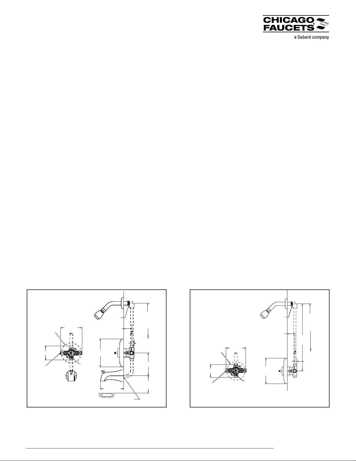
3. For tub and shower installations (see Figure 1). Pipe
bottom outlet port “TUB” directly to the diverter tub spout.
The mixer body is designed to operate without the use of a
twin ell. Pipe top outlet port “S” to the showerhead.
4. For shower only installation (see Figure 2). Pipe top outlet
port “S” directly to the showerhead and plug bottom port.
5. Rough-in guide installation:
a. When piping installation is complete and before doing
the finished wall, slide rough-in guide onto the mixer
stem and press it into place (see Figure 4).
Installation Instructions
08/09
2100 South Clearwater Drive
Des Plaines, IL 60018
P: 847/803-5000
F: 847/803-5454
Technical: 800/TEC-TRUE
www.chicagofaucets.com
1905-CP and 1907-CP
Thermostatic Valves
5-3/8" [137]
12" [305]
4" [101]
APPROX.
1-7/16" [37] MIN.
2-7/16" [62] MAX.
8-1/2" [216]
WALL
1/2" [13]
TUB RIM
1/2-14" NPT
MALE INLET
1/2" COPPER
SLIP JOINT
CONNECTION
3-1/4" [82]
5" [127]
4-5/8" [118] DIA
ROUGH-IN
GUIDE
1/2" COPPER SWEAT
CONNECTIONS
NOTE:
'T' TO BE
ON BOTTOM
AS SHOWN
78" [1981]
APPROX.
TO FINISHED
FLOOR
TUB OUTLET
TO BE PLUGGED.
PLUG BY OTHERS.
5" [127]
24" [609]
APPROX.
WALL
1-7/16" [37] MIN.
2-7/16" [62] MAX.
1/2" [13]
1/2" COPPER SWEAT
CONNECTIONS
1/2-14" NPT
MALE INLET
78" [1981]
APPROX.
TO FINISHED
FLOOR
4-5/8" [118] DIA
ROUGH-IN
GUIDE
NOTE:
'T' TO BE
ON BOTTOM
AS SHOWN
3-1/4" [82]
Figure 1: Rough-in Dimensions - Tub & Shower
See specification drawing for all other dimensions.
Figure 2: Rough-in Dimensions - Shower Only
All dotted line piping
supplied by others
All dotted line piping
supplied by others
b. The rough-in guide will insure the proper size opening for
mixer and checkstop shut-off and repair accessibility, as well
as protect the chrome-plated sleeve from damage during
drywall and tile installation.
6. To install dial gaskets, peel backing off gaskets and attach
gaskets to inside of dial plate. Attach indicator plate gasket
to the back of the trim plate making sure horizontal holes
on the gasket matches horizontal holes on the trim plate.
Indicator plate locator hole matches diagonal hole on the
trim plate. Peel off backing of the trim plate gasket and
attach to the inside top edge of the trim plate. Gasket
should be approximately 1/16" beyond the plate edge.
7. a. Install trim plate.
b. Snap on the indicator plate. Guide on the back of the
plate goes into the locator hole.
c. Install sleeve O-ring on the bonnet. Slide sleeve on the
bonnet.
CAUTION: Indicator plate must be installed before sleeve.
d. Install handle and tighten the set screw.
CAUTION: When soldering during installation process, do not
heat the valve any higher than the temperature required to
flow solder. Excessive overheating of the valve may cause
damage to the cartridge mechanism. By following this
recommendation, you will be able to solder the valve
without removing either the cartridge or the checkstop
internals. If either brazing or resistance (electric) solder is to
be used, all valve internals must be removed.
8. Maximum temperature setting adjustment (see Figure 5)
must be set on the job to in no case greater than 110°F
(43°C). The high temperature limit stop is located on the
bonnet. Rotate handle to the maximum desired outlet
temperature. With an open-end wrench, screw high
temperature limit stop into bonnet until it touches stem’s
shoulder. Close valve and open it to full hot to verify settings.
2100 South Clearwater Drive
Des Plaines, IL 60018
P: 847/803-5000
F: 847/803-5454
Technical: 800/TEC-TRUE
www.chicagofaucets.com
1905-CP and 1907-CP
Thermostatic Valves
TAG-1905 08/09
© 2009 The Chicago Faucet Company. Product specifications subject to change without notice.
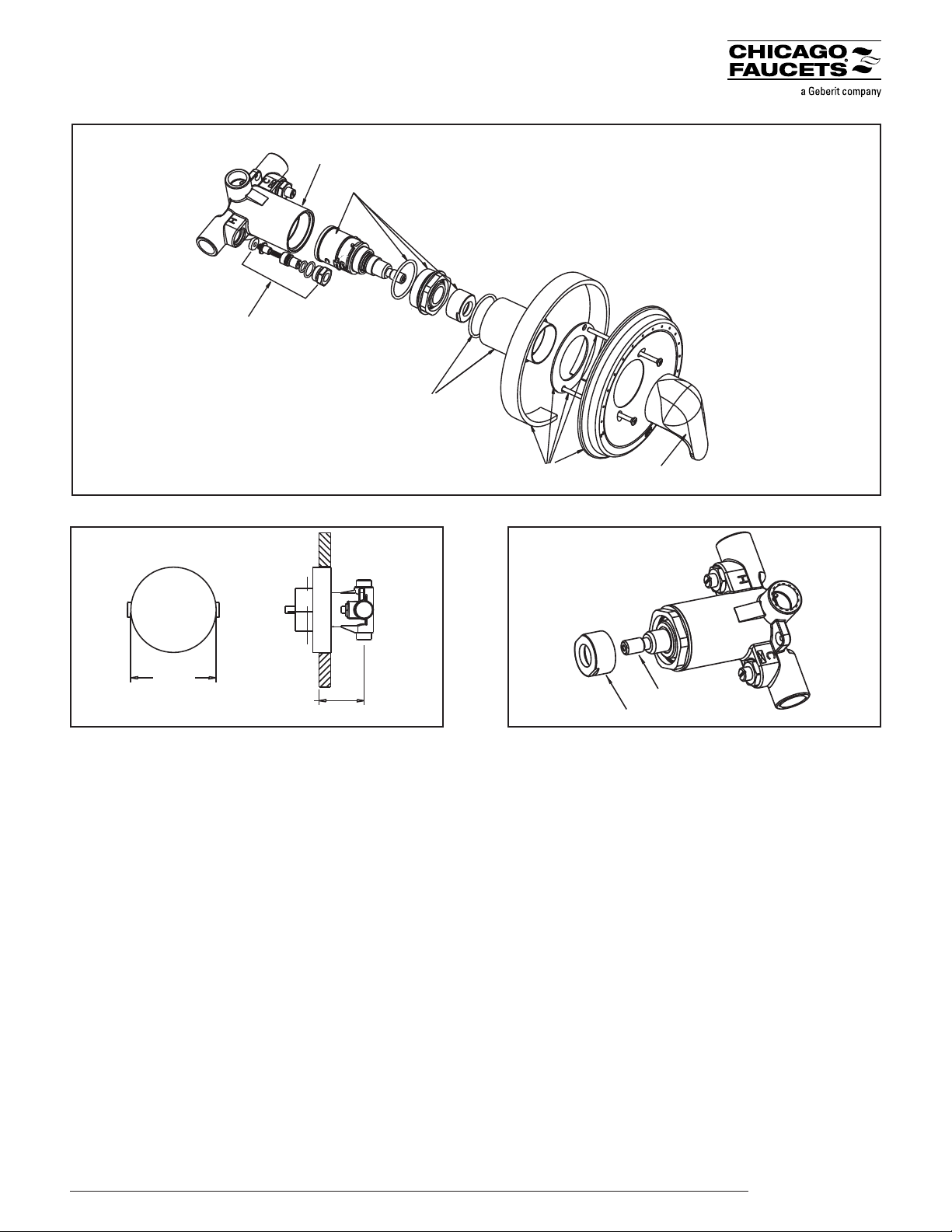
Valve
Body
Cartridge
Kit
Checkstop
Replacement Kit
Sleeve Kit
Handle Kit
Trim Plate Kit
Figure 3
High Temp. Stop
Stem
Figure 4: Rough-In Guide Figure 5: Max. Temperature Setting
2-7/16” Max.
1-7/16” Min.
4-5/8”
CHICAGO FAUCETS LIMITED WARRANTY
TO WHOM DOES THIS WARRANTY APPLY?
The Company extends the following limited warranty to the original user only.
WHAT DOES THIS WARRANTY COVER AND HOW LONG DOES IT LAST?
This Product is warranted against material manufacturing defects for a period of one (1) year from the date of Product purchase.
OTHER WARRANTIES
All other Products not covered above are warranted against material manufacturing defects for a period of one (1) year from the date of Product purchase.
WHAT THIS WARRANTY DOES NOT COVER
The Company will not be liable for any labor, transportation or consequential expenses not specifically stated above. There is NO WARRANTY in cases of damage in transit, negligence, abuse, abnormal usage,
misuse, accidents, normal wear and tear, damage due to environmental or natural elements, failure to follow the Company's instructions, unauthorized repair, incorrectly performed maintenance or repair, improper
installation or storage or use of acidic, abrasive cleaning materials. In order for this Warranty to apply, Buyer must retain and provide to the Company receipts showing date of Product purchase and documenting
proper maintenance. Any oral or written description of the Products is for the sole purpose of identifying the Products and shall not be construed as an express warranty. THE COMPANY SHALL NOT BE
LIABLE TO BUYER, OR TO ANYONE CLAIMING UNDER BUYER, FOR ANY OTHER OBLIGATIONS OR LIABILITIES, INCLUDING, BUT NOT LIMITED TO, OBLIGATIONS OR LIABILITIES
ARISING OUT OF BREACH OF CONTRACT OR WARRANTY, NEGLIGENCE OR OTHER TORT OR ANY THEORY OF STRICT LIABILITY, WITH RESPECT TO THE PRODUCTS OR THE
COMPANY'S ACTS OR OMISSIONS OR OTHERWISE. THE COMPANY AND BUYER AGREE THAT THE EXPRESS WARRANTIES DESCRIBED ABOVE ARE EXCLUSIVE AND IN LIEU OF
ALL OTHER WARRANTIES. ALL OTHER EXPRESS WARRANTIES ARE DISCLAIMED. FOR COMMERCIAL PRODUCTS, ALL WARRANTIES IMPLIED BY LAW, INCLUDING WITHOUT
LIMITATION THE IMPLIED WARRANTIES OF MERCHANTABILITY AND FITNESS FOR A PARTICULAR PURPOSE, ARE DISCLAIMED. FOR CONSUMER PRODUCTS, WARRANTIES
IMPLIED BY LAW, INCLUDING THOSE OF MERCHANTABILITY AND FITNESS FOR A PARTICULAR PURPOSE, ARE EXPRESSLY LIMITED TO THE PERIOD OF THE EXPRESS
LIMITED WARRANTY STATED ABOVE FOR THE RELEVANT PRODUCT. Some States do not allow limitations on how long an implied warranty lasts, so the above limitation may not apply to you. Any
assistance the Company provides to or procures for Buyer outside the terms, limitations or exclusions of this warranty will not constitute a waiver of the terms, limitations or exclusions of this limited warranty, nor
will such assistance extend or revive the warranty. The Company will not reimburse Buyer for any expenses incurred by Buyer in repairing, correcting or replacing any defective Products, except for expenses incurred
with the Company's prior written permission.
HOW TO GET SERVICE
For complete warranty details, or to provide notice of a warranty claim or request warranty service, contact your Chicago Faucets Sales Representative or The Chicago Faucet Company, Customer Service,
2100 S. Clearwater Drive, Des Plaines, Illinois 60018 or 847-803-5000. As the Company's sole and exclusive obligation under this warranty (and Buyer's sole and exclusive remedy), upon prompt written
notice of breach from Buyer during the warranty period, the Company will either replace or repair the defective Product or refund the wholesale purchase price, at its option, if an inspection by the Company
discloses defects in material or workmanship covered by this warranty. These warranty provisions do not cover the battery shipped with the electronic products.
LIMITATION ON DAMAGES
IN NO EVENT SHALL THE COMPANY BE LIABLE FOR INCIDENTAL, CONSEQUENTIAL, INDIRECT OR SPECIAL DAMAGES. WITHOUT LIMITING THE FOREGOING, THE
COMPANY SHALL NOT BE LIABLE FOR ANY DAMAGE A PALM DEVICE OR ANY SOFTWARE OR RELATED EQUIPMENT ALLEGEDLY CAUSES TO A SYSTEM OR OTHERWISE.
THE COMPANY'S AGGREGATE LIABILITY WITH RESPECT TO A DEFECTIVE PRODUCT AND THIS CONTRACT SHALL BE LIMITED TO AN AMOUNT EQUAL TO THE MONIES
PAID TO THE COMPANY FOR THAT DEFECTIVE PRODUCT.
Some states do not allow the exclusion or limitation of incidental or consequential damages, so the above limitation or exclusion may not apply to you.
HOW DOES STATE LAW APPLY?
This warranty gives you specific legal rights, and you may also have other rights which vary from state to state.
Restrictions Apply
Additional Technical Documentation
Please visit the product page at www.chicagofaucets.com for additional instructions in French and Spanish languages.
 Loading...