


Chicago Faucet 116.600.21.1 Installation Manual
Printed in USA © 0704
Tag # 317
Geberit V
Geberit V
ortex & V
ortex & V
ortex Max Diaphragm Flushometer V
ortex Max Diaphragm Flushometer V
alves
alves
INST
INST
ALLA
ALLA
TION INSTRUCTIONS
TION INSTRUCTIONS
Geberit Manufacturing, Inc.
1100 Boone Drive, Michigan City, IN 46360
Phone: (847) 803-5000 • Fax: (847) 298-3101
For Technical Assistance (800) TEC-TRUE (800-832-8783)
www.chicagofaucets.com
NOTE
Pressurized plumbing fixture flushing devices
(flushometers) shall be installed in accordance
with manufacturer’s recommendations. The
supply piping to these devices shall be securely
anchored to the building structure to prevent
installed device from unnecessary movement
when operated by the user. Care shall be exercised when installing the device to prevent marring the exposed significant surface.
Copyrights
© 2004 Geberit. All rights reserved. The information in this manual is subject to change without notice.
Notice to Installers
Please leave this manual with the facility manager after completing the flushometer installation. This document contains information necessary for routine maintenance and servicing.
TABLE OF CONTENTS
Product Overview...............................2
Vortex Flushometer Features............2
Vortex Max Flushometer Features....3
Prior to Installation.............................4
Tools Required for Installation..........4
Water Pressure and Volume..............4
Chrome Plating...................................4
Technical Support ..............................4
Safety Information..............................4
Rough-In Dimensions ........................5
Component Identification ..................6
Installation .......................................7-9
Service Procedures..........................10
Troubleshooting ..........................11-13
Warranty.......................................13-15
Las instrucciones en espanol ........17
Les instructions en francais ...........31
ADA Compliant
®
In compliance with ASSE 1037
U
P
C
C
Geberit Vortex Diaphragm Flushometer Valves
Installation & Maintenance Instructions
Printed in USA © 0704
Tag # 317
2
Vortex Diaphragm Flushometer Features
• Durable, proven diaphragm performance
• Accurate, low consumption flushing performance
• Vandal resistance built in, including set screw on stop cap
• Adjustable slip joint tailpiece
• Non-hold open handle
• ADA compliant
• Renewable main valve seat
• Available in a wide variety of configurations to meet most installation needs.
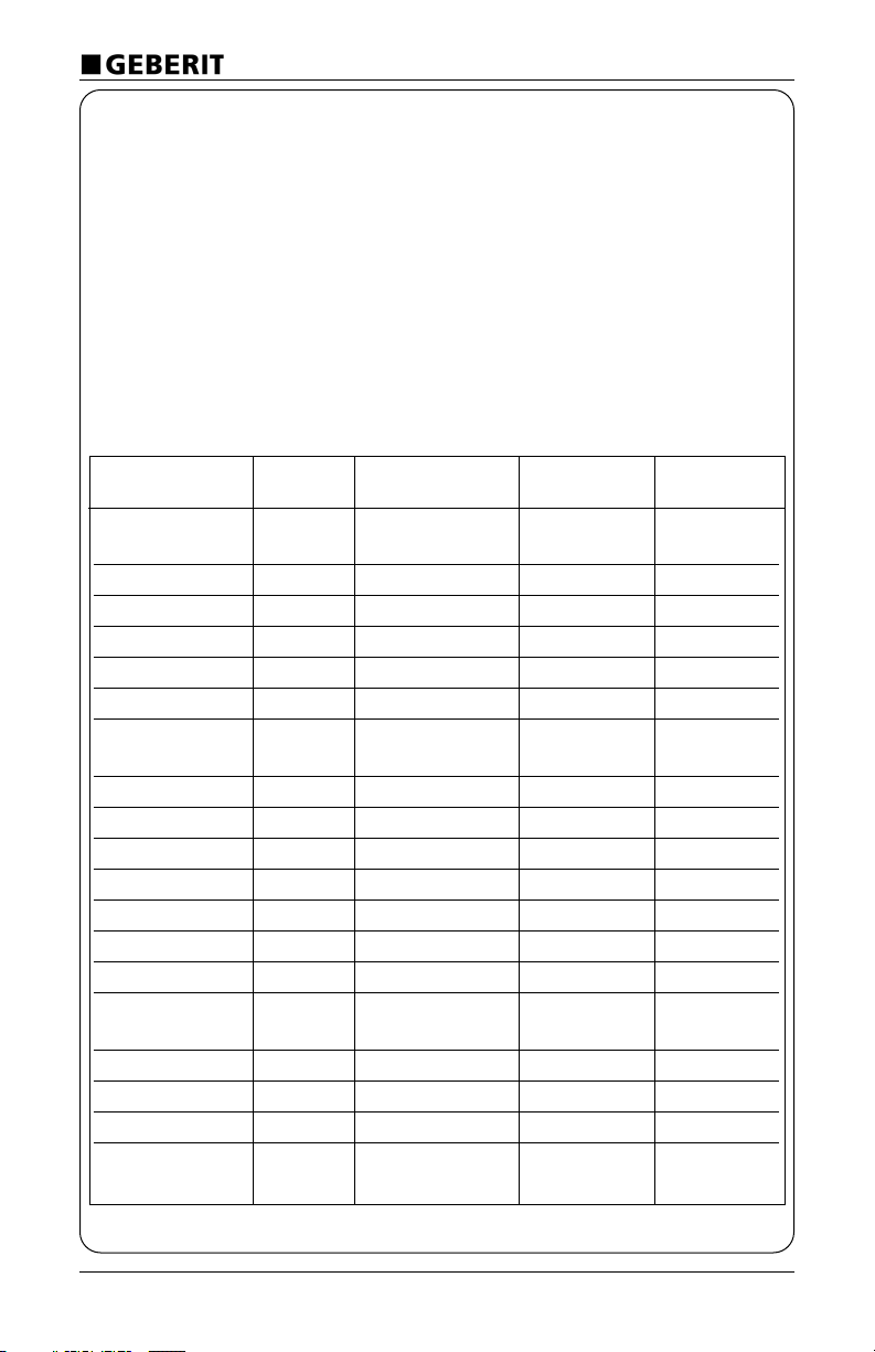
* Rough-in dimension is the vertical distance from CL of rough-in to top of china.
Product Overview
Geberit Vortex Flushometers are reliable, competitively priced manual flushometer valves
backed by a trusted name in plumbing products with a wealth of experience and excellent customer service.
Model Number Flush Rough-In Spud Type Stop Valve
Volume Dimension (in.)*
Urinal
116.600.21.1 1.0 GPF 11½ ¾ Top ¾ I.P.S.
116.601.21.1 1.0 GPF 11½ 1¼ Top 1 I.P.S.
116.602.21.1 1.5 GPF 11½ ¾ Top ¾ I.P.S.
116.603.21.1 1.0 GPF 11½ 1¼ Top 1 I.P.S.
116.604.21.1 1.0 GPF Valve Only None None
116.605.21.1 1.0 GPF Valve Only None None
Water Closet
116.620.21.1 1.6 GPF 11½ 1½ Top 1 I.P.S.
116.621.21.1 3.5 GPF 11½ 1½ Top 1 I.P.S.
116.622.21.1 1.6 GPF 24 1½ Top 1 I.P.S.
116.623.21.1 3.5 GPF 24 1½ Top 1 I.P.S.
116.624.21.1 1.6 GPF 11½ 1½ Back 1 I.P.S.
116.625.21.1 3.5 GPF 11½ 1½ Back 1 I.P.S.
116.626.21.1 1.6 GPF Valve Only None None
116.627.21.1 3.5 GPF Valve Only None None
Bedpan Washers
116.640.21.1 1.6 GPF 34 1½ Top 1 I.P.S.
116.641.21.1 3.5 GPF 34 1½ Top 1 I.P.S.
116.642.21.1 1.6 GPF Retrofit 1½ Top 1 I.P.S.
116.643.21.1 3.5 GPF Retrofit 1½ Top 1 I.P.S.
Service Sink
116.660.21.1 4.5 GPF 24 1½ Top 1 I.P.S.

Geberit Vortex Diaphragm Flushometer Valves
Installation & Maintenance Instructions
Printed in USA © 0704
Tag # 317
3
* Rough-in dimension is the vertical distance from CL of rough-in to top of china.
Vortex Max Diaphragm Flushometer Features
• High performance diaphragm performance with self cleaning orifice
• Stainless steel particulate filter at inlet
• Accurate, low consumption flushing performance
• Vandal resistance built in, including set screw on stop cap
• Adjustable slip joint tailpiece
• Non-hold open handle
• ADA compliant
• Renewable main valve seat
• Available in a wide variety of configurations to meet most installation needs
Model Number Flush Rough-In Spud Type Stop Valve
Volume Dimension (in.)*
Urinal
116.800.21.1 1.0 GPF 11½ ¾ Top ¾ I.P.S.
116.801.21.1 1.0 GPF 11½ 1¼ Top 1 I.P.S.
116.802.21.1 1.5 GPF 11½ ¾ Top ¾ I.P.S.
116.803.21.1 1.5 GPF 11½ 1¼ Top 1 I.P.S.
116.804.21.1 1.0 GPF Valve Only None None
116.805.21.1 1.5 GPF Valve Only None None
Water Closet
116.820.21.1 1.6 GPF 11½ 1½ Top 1 I.P.S.
116.821.21.1 3.5 GPF 11½ 1½ Top 1 I.P.S.
116.822.21.1 1.6 GPF 24 1½ Top 1 I.P.S.
116.823.21.1 3.5 GPF 24 1½ Top 1 I.P.S.
116.824.21.1 1.6 GPF 11½ 1½ Back 1 I.P.S.
116.825.21.1 3.5 GPF 11½ 1½ Back 1 I.P.S.
116.826.21.1 1.6 GPF Valve Only None None
116.827.21.1 3.5 GPF Valve Only None None
Bedpan Washers
116.840.21.1 1.6 GPF 34 1½ Top 1 I.P.S.
116.841.21.1 3.5 GPF 34 1½ Top 1 I.P.S.
116.842.21.1 1.6 GPF Retrofit 1½ Top 1 I.P.S.
116.843.21.1 3.5 GPF Retrofit 1½ Top 1 I.P.S.
Geberit Vortex Diaphragm Flushometer Valves
Installation & Maintenance Instructions
Printed in USA © 0704
Tag # 317
4
Prior To Installation
Before installing the flushometer, be sure
the following items are properly installed:
• Urinal fixture
• Drain line
• Water supply line
Tools Required for Installation
• Slotted screwdriver
• Standard box wrenches
• Smooth jawed adjustable wrench or
Chicago Faucet Quaturn wrench.
Water Pressure and Volume
Geberit valves require a minimum operating pressure of 10 psi while flushing. All
plumbing fixtures demand at least 10 psi,
so if this minimum requirement is met, the
valve should function properly.
In addition to pressure, volume requirements must be met to secure an adequate
syphon. Most toilets require a
minimum flow rate of 30 gpm. The lower
the pressure, the larger the piping must be
to supply the minimum flow.
Geberit valves are designed to operate at
water pressure up to 100 psi. Ideally, pressures should range between 30-60 psi. At
pressures of 80 psi and above, we recommend the use of pressure reducing valves
in supply lines. At higher pressures,
splashing is inevitable, noise is increased
and the life span of all plumbing brass is
reduced.
It is recommended that air chambers
and/or water hammer arrestors be
installed with flush valves. They should be
installed as close to the fixture as possible.
Air chambers are helpful in supplying a
reservoir of water in the event of sudden
pressure drops.
Chrome Plating
If installation is into new construction, we
recommend protecting all chrome surfaces from acid or cleaning fluid that can
discolor chrome, until the building is occupied. This will help to protect the surface
from damage.
Do not use serrated-jaw wrenches
on chrome surfaces. Use a smoothjawed adjustable wrench or Chicago
Faucet Quaturn wrench.
Technical Support
For additional technical assistance, visit
our website at: www.us.geberit.com, or
call:
1-800-TEC-TRUE (1-800-832-8783)
IMPORTANT! Installations may be performed at different times of construction by different individuals. For this
reason, these instructions should be
left on-site with the facility or maintenance manager.
Safety Information
• Read this entire instruction sheet to
ensure proper installation.
• Compliance and conformity to local
codes and ordinances is the
responsibility of the installer.
Flush all the water supply lines
before making connections.
CAUTION indicates a practice or
condition that MAY result in damage to
the equipment if the instruction or
notice is ignored.
Geberit Vortex Diaphragm Flushometer Valves
Installation & Maintenance Instructions
Printed in USA © 0704
Tag # 317
5
po MIN.
[57mm]
2-1/4
" MIN.
[57mm]
2-1/4
MIN.
[57mm]
2-1/4 po
MIN.
[57mm]
2-1/4 po
11-1/2 po
[292mm]
6-1/2 po
MIN.
[165mm]
po
[292mm]
11-1/2
[121mm]
4-3/4 po
[121mm]
4-3/4"
24"
[610mm]
"
[292mm]
11-1/2
" MIN.
[57mm]
2-1/4
[292mm]
11-1/2 po
[121mm]
4-3/4 po
" MIN.
[57mm]
2-1/4
24 "
[610mm]
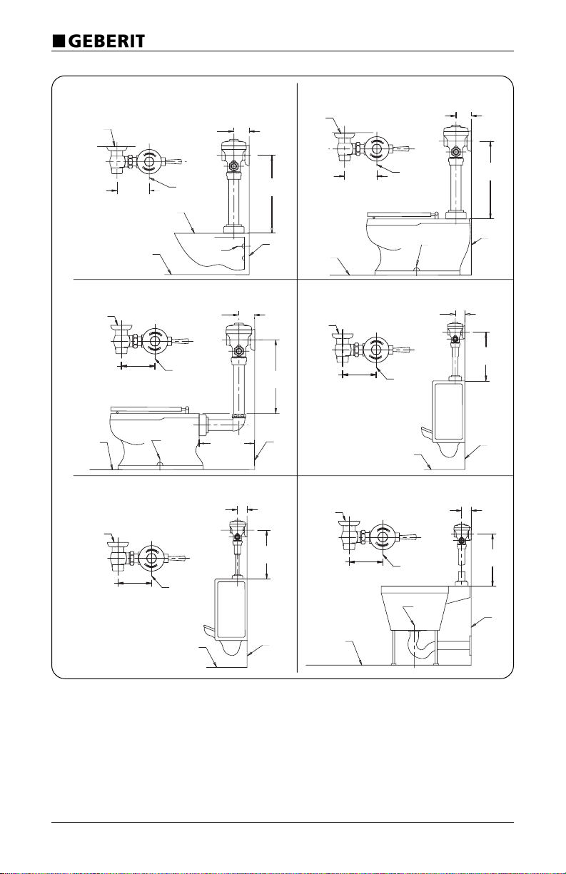
MODÈLE 116.620.21.1, 116.820.21.1 - 1.6 GPF (6.0 LPF)
MODÈLE 116.621.21.1, 116.821.21.1 - 3.5 GPF (13.2 LPF)
MODEL 116.622.21.1, 116.822.21.1 - 1.6 GPF (6.0 LPF)
MODEL 116.623.21.1, 116.823.21.1 - 3.5 GPF (13.2 LPF)
MODÈLE 116.624.21.1, 116.824.21.1 - 1.6 GPF (6.0 LPF)
MODÈLE 116.625.21.1, 116.825.21.1 - 3.5 GPF (13.2 LPF)
MODEL 116.601.21.1, 116.801.21.1 - 1.0 GPF (3.8 LPF)
MODEL 116.603.21.1, 116.803.21.1 - 1.5 GPF (5.7 LPF)
MODÈLE 116.600.21.1, 116.800.21.1 - 1.0 GPF (3.8 LPF)
MODÈLE 116.602.21.1, 116.802.21.1 - 1.5 GPF (5.7 LPF)
MODEL 116.660.21.1 - 4.5 GPF (17.0 LPF)
N.C. DE
L'APPAREIL
SANITAIRE
C/L OF
FIXTURE
FIN.
FLOOR
C/L OF
WASTE
MUR FINI
SOL FINI
SOL FINI
N.C. DE
VIDANGE
N.C. DE L'APPAREIL
SANITAIRE
VIDANGE À FIXATION MURALE
MUR FINI
SOL FINI
ALIMENTATION
1" IPS
FIN.
WALL
1" IPS
SUPPLY
FIN.
WALL
FIN.
FLOOR
MUR
FINI
ALIMENTATION
1" IPS
FIN.
WALL
FIN.
FLOOR
C/L OF
WASTE
"
[121mm]
4-3/4
C/L
OF FIXTURE
1" IPS
SUPPLY
[121mm]
4-3/4 po
N.C. DE
VIDANGE
3/4" IPS
SUPPLY
"
[121mm]
4-3/4
C/L
OF FIXTURE
1" IPS
SUPPLY
N.C. DE
VIDANGE
ROUGH-IN DIMENSIONS (INCHES/MILLIMETERS)