

Page 1
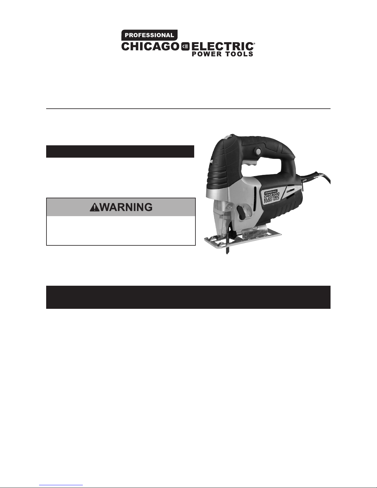
Orbital Jigsaw With LED, Dust Blower and
Laser Cutting Guide
Item 68821
Read this material before using this product.
Failure to do so can result in serious injury.
SAVE THIS MANUAL.
When unpacking, make sure that the product is intact and undamaged.
If any parts are missing or broken, please call 1-800-444-3353 as soon as possible.
Visit our website at: http://www.harborfreight.com
Email our technical support at: [email protected]
Copyright© 2011 by Harbor Freight Tools®. All rights reserved. No portion of this manual or
any artwork contained herein may be reproduced in any shape or form without the express
written consent of Harbor Freight Tools. Diagrams within this manual may not be drawn
proportionally. Due to continuing improvements, actual product may differ slightly from the
product described herein. Tools required for assembly and service may not be included.
Page 2
Page 2 For technical questions, please call 1-800-444-3353. SKU 68821
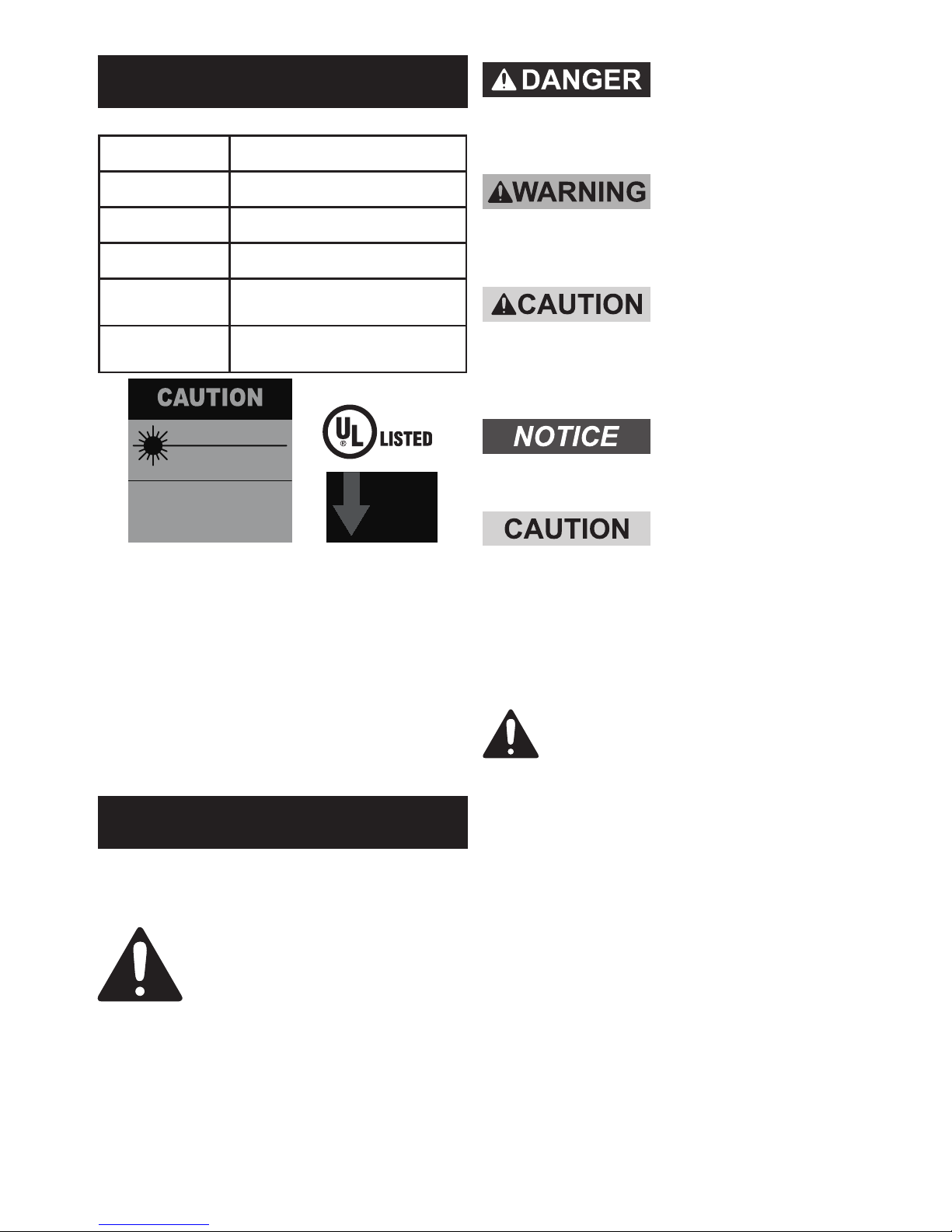
Specications
Electrical Input 120 V~ / 60 Hz / 6.5 A (Rated)
Cutting Speed 500-3000 Strokes Per Minute
Stroke Length 1-9/16 IN.
Footplate Tilt 0-45°, left or right
Blade Types
Uses T-Shank or
U-Shank Blades
Batteries
2 “AAA” for Laser Light
(not included)
LASER LIGHT
DO NOT STARE INTO BEAM
Max. Output: <1 mW,
Wavelength: 650 nm
CLASS II LASER PRODUCT
This product complies with
21 CFR 1040.10 and 1040.11
Diode Mfr.:
Zhenjiang Bouncer Stone
Electron Co., LTD, No.16, Guyang Xincun,
Dingmao, Zhenjiang City, China
Manufacture Date: ___________, ______
AVOID
EXPOSURE
Laser light is
emitted from
this opening.
Save This Manual
Keep this manual for the safety warnings and
precautions, assembly, operating, inspection,
maintenance and cleaning procedures. Write
the product’s serial number in the back of the
manual near the assembly diagram (or month
and year of purchase if product has no
number). Keep this manual and the receipt
in a safe and dry place for future reference.
Important Safety Information
In this manual, on the labeling, and all other
information provided with this product:
This is the safety alert symbol.
It is used to alert you to potential
personal injury hazards. Obey
all safety messages that
follow this symbol to avoid
possible injury or death.
DANGER indicates a hazardous
situation which, if not avoided, will
result in death or serious injury.
WARNING indicates a hazardous
situation which, if not avoided, could
result in death or serious injury.
CAUTION, used with the safety alert
symbol, indicates a hazardous situation
which, if not avoided, could result
in minor or moderate injury.
NOTICE is used to address practices
not related to personal injury.
CAUTION, without the safety alert
symbol, is used to address practices
not related to personal injury.
General Power Tool
Safety Warnings
WARNING Read all safety warnings
and instructions. Failure to follow the
warnings and instructions may result in
electric shock, re and/or serious injury.
Save all warnings and instructions
for future reference.
The term ″power tool″ in the warnings
refers to your mains‑operated
(corded) power tool.
1. Work area safety
a. Keep work area clean and well lit.
Cluttered or dark areas invite accidents.
b. Do not operate power tools in
explosive atmospheres, such as in the
presence of ammable liquids, gases
or dust. Power tools create sparks
which may ignite the dust or fumes.
c. Keep children and bystanders
away while operating a power tool.
Distractions can cause you to lose control.
E194601
Page 3

Page 3For technical questions, please call 1-800-444-3353.SKU 68821
2. Electrical safety
a. Power tool plugs must match the
outlet. Never modify the plug in
any way. Do not use any adapter
plugs with grounded power tools.
Unmodied plugs and matching outlets
will reduce risk of electric shock.
b. Avoid body contact with grounded
surfaces such as pipes, radiators,
ranges and refrigerators. There is an
increased risk of electric shock
if your body is grounded.
c. Do not expose power tools to rain or
wet conditions. Water entering a power
tool will increase the risk of electric shock.
d. Do not abuse the cord. Never use the
cord for carrying, pulling or unplugging
the power tool. Keep cord away from
heat, oil, sharp edges or moving
parts. Damaged or entangled cords
increase the risk of electric shock.
e. When operating a power tool
outdoors, use an extension cord
suitable for outdoor use. Use
of a cord suitable for outdoor use
reduces the risk of electric shock.
f. If operating a power tool in a damp
location is unavoidable, use a Ground
Fault Circuit Interrupter (GFCI)
protected supply. Use of a GFCI
reduces the risk of electric shock.
3. Personal safety
a. Stay alert, watch what you are
doing and use common sense when
operating a power tool. Do not use
a power tool while you are tired or
under the inuence of drugs, alcohol
or medication. A moment of inattention
while operating power tools may
result in serious personal injury.
b. Use personal protective equipment.
Always wear eye protection. Safety
equipment such as a dust mask,
non-skid safety shoes, a hard hat, or
hearing protection used for appropriate
conditions will reduce personal injuries.
c. Prevent unintentional starting. Ensure
the switch is in the off-position before
connecting to power source, picking
up or carrying the tool. Carrying
power tools with your nger on the
switch or energizing power tools that
have the switch on invites accidents.
d. Remove any adjusting key or wrench
before turning the power tool on.
A wrench or a key left attached to
a rotating part of the power tool
may result in personal injury.
e. Do not overreach. Keep proper
footing and balance at all times. This
enables better control of the power
tool in unexpected situations.
f. Dress properly. Do not wear loose
clothing or jewelry. Keep your hair,
clothing and gloves away from moving
parts. Loose clothes, jewelry or long
hair can be caught in moving parts.
g. If devices are provided for the
connection of dust extraction
and collection facilities, ensure
these are connected and properly
used. Use of these devices can
reduce dust‑related hazards.
h. Only use safety equipment that has
been approved by an appropriate
standards agency. Unapproved safety
equipment may not provide adequate
protection. Eye protection must be
ANSI‑approved and breathing protection
must be NIOSH‑approved for the
specic hazards in the work area.
4. Power tool use and care
a. Do not force the power tool. Use
the correct power tool for your
application. The correct power tool
will do the job better and safer at the
rate for which it was designed.
b. Do not use the power tool if the
switch does not turn it on and off.
Any power tool that cannot be
controlled with the switch is
dangerous and must be repaired.
Page 4

Page 4 For technical questions, please call 1-800-444-3353. SKU 68821
c. Disconnect the plug from the
power source before making any
adjustments, changing accessories, or
storing power tools. Such preventive
safety measures reduce the risk of
starting the power tool accidentally.
d. Store idle power tools out of the
reach of children and do not allow
persons unfamiliar with the power tool
or these instructions to operate the
power tool. Power tools are dangerous
in the hands of untrained users.
e. Maintain power tools. Check for
misalignment or binding of moving
parts, breakage of parts and any
other condition that may affect the
power tool’s operation. If damaged,
have the power tool repaired
before use. Many accidents are caused
by poorly maintained power tools.
f. Keep cutting tools sharp and clean.
Properly maintained cutting tools with
sharp cutting edges are less likely
to bind and are easier to control.
g. Use the power tool, accessories and
tool bits etc. in accordance with these
instructions, taking into account the
working conditions and the work to
be performed. Use of the power tool for
operations different from those intended
could result in a hazardous situation.
5. Service
a. Have your power tool serviced by
a qualied repair person using
only identical replacement parts.
This will ensure that the safety of
the power tool is maintained.
Jigsaw Safety Warnings
1. Hold power tool by insulated gripping
surfaces when performing an operation
where cutting tool may contact hidden
wiring or its own cord. Contact with a
″live″ wire will make exposed metal parts
of the tool ″live″ and shock the operator.
2. Use clamps or another practical way
to secure and support the work piece
to a stable platform. Holding the work
by hand or against your body leaves it
unstable and may lead to loss of control.
3. Maintain labels and nameplates on the tool.
These carry important safety information.
If unreadable or missing, contact Harbor
Freight Tools for a replacement.
4. Avoid unintentional starting. Prepare to
begin work before turning on the tool.
5. Do not lay the tool down until it has come to
a complete stop. Moving parts can grab the
surface and pull the tool out of your control.
6. When using a handheld power tool,
maintain a rm grip on the tool with
both hands to resist starting torque.
7. Do not leave the tool unattended when
it is plugged into an electrical outlet.
Turn off the tool, and unplug it from
its electrical outlet before leaving.
8. This product is not a toy.
Keep it out of reach of children.
9. People with pacemakers should consult their
physician(s) before use. Electromagnetic
elds in close proximity to heart pacemaker
could cause pacemaker interference or
pacemaker failure. In addition, people with
pacemakers should:
• Avoid operating alone.
• Do not use with power switch locked on.
• Properly maintain and inspect to avoid
electrical shock.
• Any power cord must be properly
grounded. Ground Fault Circuit Interrupter
(GFCI) should also be implemented –
it prevents sustained electrical shock.
10. WARNING: Handling the cord on this product
will expose you to lead, a chemical known to
the State of California to cause cancer, and
birth defects or other reproductive harm. Wash
hands after handling.
(California Health & Safety Code
§ 25249.5, et seq.)
Page 5

Page 5For technical questions, please call 1-800-444-3353.SKU 68821
11. WARNING: Some dust created by power
sanding, sawing, grinding, drilling, and
other construction activities, contains
chemicals known [to the State of California]
to cause cancer, birth defects or other
reproductive harm. Some examples of
these chemicals are:
• Lead from lead-based paints
• Crystalline silica from bricks and cement or
other masonry products
• Arsenic and chromium from
chemically treated lumber
Your risk from these exposures varies,
depending on how often you do this type
of work. To reduce your exposure to these
chemicals: work in a well ventilated area, and
work with approved safety equipment, such as
those dust masks that are specially designed
to lter out microscopic particles.
(California Health & Safety Code
§ 25249.5, et seq.)
12. The warnings, precautions, and instructions
discussed in this instruction manual cannot
cover all possible conditions and situations
that may occur. It must be understood by
the operator that common sense and caution
are factors which cannot be built into this
product, but must be supplied by the operator.
Vibration Safety
This tool vibrates during use.
Repeated or long-term exposure to
vibration may cause temporary or
permanent physical injury, particularly
to the hands, arms and shoulders. To
reduce the risk of vibration-related injury:
1. Anyone using vibrating tools regularly or for
an extended period should rst be examined
by a doctor and then have regular medical
check-ups to ensure medical problems are
not being caused or worsened from use.
Pregnant women or people who have impaired
blood circulation to the hand, past hand
injuries, nervous system disorders, diabetes,
or Raynaud’s Disease should not use this tool.
If you feel any symptoms related to
vibration (such as tingling, numbness,
and white or blue ngers), seek medical
advice as soon as possible.
2. Do not smoke during use. Nicotine reduces
the blood supply to the hands and ngers,
increasing the risk of vibration-related injury.
3. Wear suitable gloves to reduce the
vibration effects on the user.
4. Use tools with the lowest vibration
when there is a choice.
5. Include vibration-free periods
each day of work.
6. Grip tool as lightly as possible
(while still keeping safe control of it).
Let the tool do the work.
7. To reduce vibration, maintain the tool as
explained in this manual. If any abnormal
vibration occurs, stop use immediately.
SAVE THESE
INSTRUCTIONS.
Grounding
TO PREVENT ELECTRIC SHOCK
AND DEATH FROM
INCORRECT GROUNDING
WIRE CONNECTION:
Check with a qualied electrician if you are in
doubt as to whether the outlet is properly
grounded. Do not modify the power cord plug
provided with the tool. Never remove the
grounding prong from the plug. Do not use
the tool if the power cord or plug is damaged.
If damaged, have it repaired by a service
facility before use. If the plug will not t the
outlet, have a proper outlet installed by a
qualied electrician.
Page 6
Page 6 For technical questions, please call 1-800-444-3353. SKU 68821
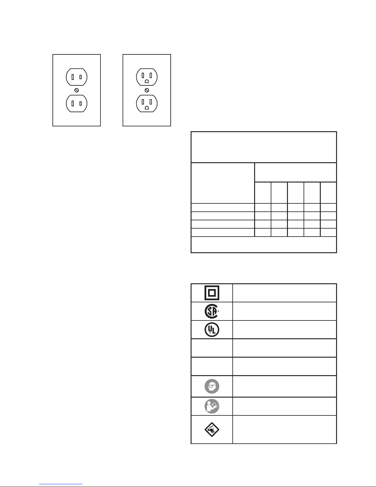
Double Insulated Tools:
Tools with Two Prong Plugs
Outlets for 2-Prong Plug
1. Tools marked “Double Insulated” do not
require grounding. They have a special
double insulation system which satises
OSHA requirements and complies with
the applicable standards of Underwriters
Laboratories, Inc., the Canadian Standard
Association, and the National Electrical Code.
2. Double insulated tools may be used in either
of the 120 volt outlets shown in the preceding
illustration. (See Outlets for 2-Prong Plug.)
Extension Cords
1. Grounded tools require a
three wire extension cord.
Double Insulated tools can use either
a two or three wire extension cord.
2. As the distance from the supply outlet
increases, you must use a heavier gauge
extension cord. Using extension cords
with inadequately sized wire causes a
serious drop in voltage, resulting in loss
of power and possible tool damage.
(See Table A on page 6.)
3. The smaller the gauge number of the wire,
the greater the capacity of the cord. For
example, a 14 gauge cord can carry a higher
current than a 16 gauge cord. (See Table A.)
4. When using more than one extension cord
to make up the total length, make sure
each cord contains at least the minimum
wire size required. (See Table A.)
5. If you are using one extension cord for more
than one tool, add the nameplate amperes
and use the sum to determine the required
minimum cord size. (See Table A.)
6. If you are using an extension cord
outdoors, make sure it is marked with the
sufx “W-A” (“W” in Canada) to indicate
it is acceptable for outdoor use.
7. Make sure the extension cord is
properly wired and in good electrical
condition. Always replace a damaged
extension cord or have it repaired by a
qualied electrician before using it.
8. Protect the extension cords from
sharp objects, excessive heat,
and damp or wet areas.
TABLE A: RECOMMENDED
MINIMUM WIRE GAUGE FOR
EXTENSION CORDS* (120/240 VOLT)
NAMEPLATE
AMPERES
(at full load)
EXTENSION CORD
LENGTH
25´
50´
75´
100´
150´
5.1 – 7.0 18 16 14 12 12
7.1 – 12.0 18 14 12 10 -
12.1 – 16.0 14 12 10 - -
16.1 – 20.0 12 10 - - -
* Based on limiting the line voltage drop to
ve volts at 150% of the rated amperes.
Symbology
Double Insulated
Canadian Standards Association
Underwriters Laboratories, Inc.
V~
Volts Alternating Current
A
Amperes
WARNING marking concerning Risk
of Eye Injury. Wear ANSI-approved
safety goggles with side shields.
Read the manual before
set-up and/or use.
WARNING marking concerning
Risk of Electric Shock.
Properly connect power cord
to appropriate outlet.
Page 7
Page 7For technical questions, please call 1-800-444-3353.SKU 68821
Instructions for Putting into Use
Read the ENTIRE IMPORTANT
SAFETY INFORMATION section at the
beginning of this manual including
all text under subheadings therein
before set up or use of this product.
TO PREVENT SERIOUS INJURY FROM
ACCIDENTAL OPERATION:
Turn the Power Switch of the tool off
and unplug the tool from its electrical
outlet before assembling or making
any adjustments to the tool.
Note: For additional information regarding
the parts listed in the following pages, refer to
Parts List and Assembly Diagram on page 12.
Blade Installation
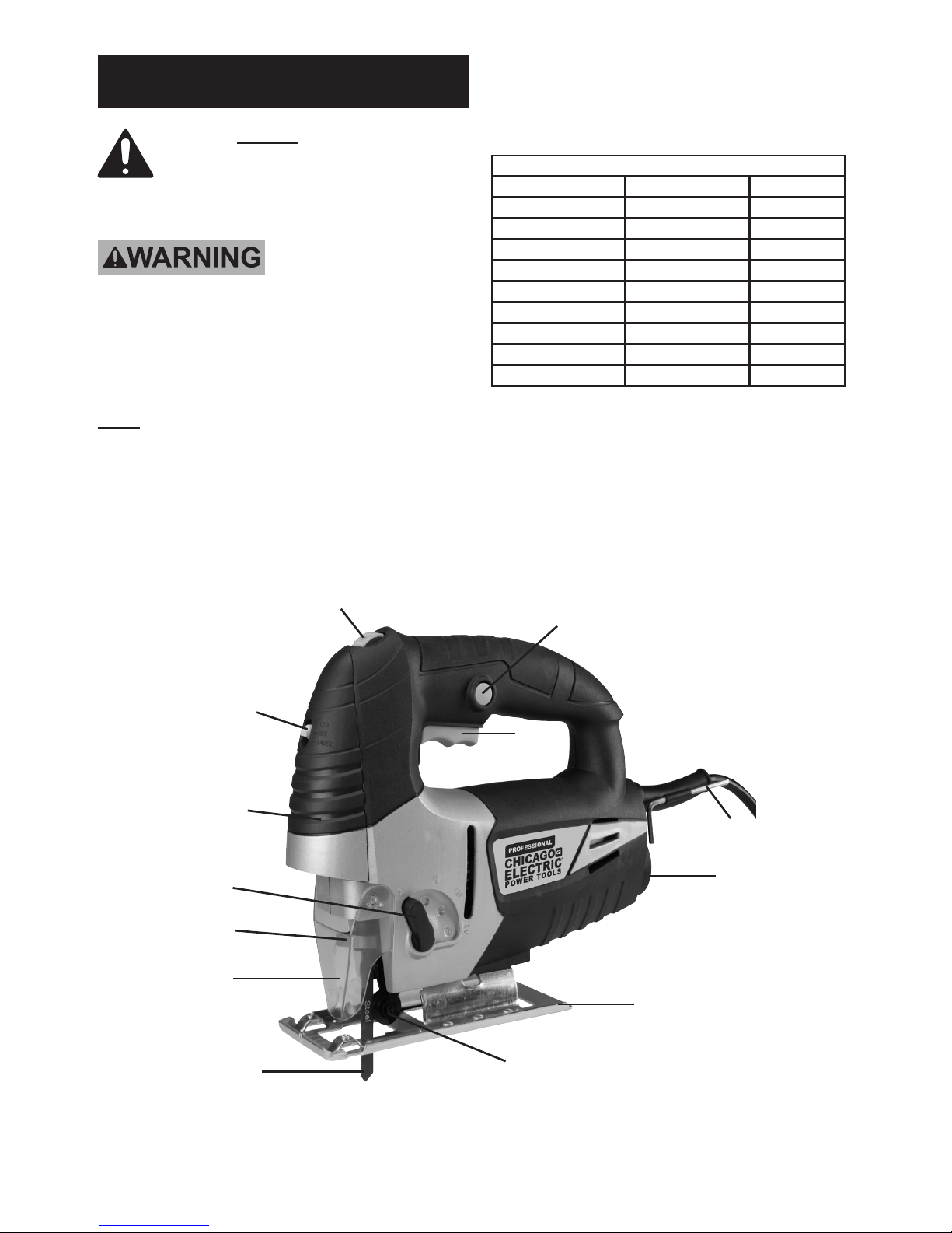
1. Refer to the Chart below to select the proper
Saw Blade for the material being cut.
BLADE SELECTION AND SUITABLE SPEED
Material TPI Speed
Soft Wood 6 6
Hardwood 6 5
Plastic 12 4 ~ 6
Aluminum 12 3 ~ 6
Steel 24 2 ~ 4
Tile 24 1 ~ 3
Glass 32 1 ~ 3
Leather (Knife Edge) 4 ~ 6
Rubber (Knife Edge) 4 ~ 6
Trigger Lock
Trigger
(16)
Speed Switch
Laser Switch
(46)
Orbital Mode
Level (12)
Blade Release
Lever
Blade Cover
(53)
Hex Key
Dust Chute
Connector
Base Plate (22)
Blade
Adjustment Knob (55)
Laser Shell
(45)
Page 8
Page 8 For technical questions, please call 1-800-444-3353. SKU 68821
WARNING! Wear ANSI-approved safety goggles
and heavy-duty work gloves when changing blade.
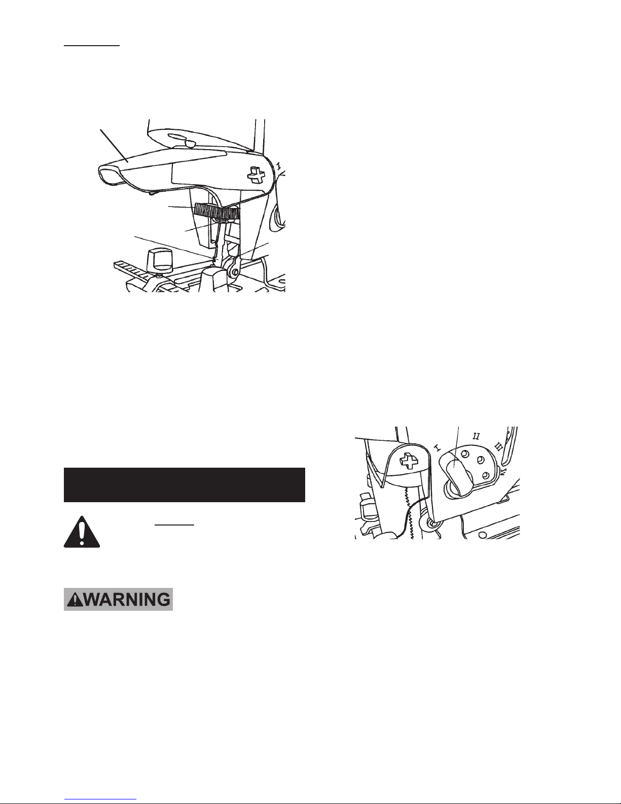
2. Once the proper blade is selected, lift the
Blade Cover (53) up to access the Blade
Release Lever. See Figure 1, below.
Blade Cover (53)
Blade Release
Lever
Collet
Blade
Roller
Guide
Figure 1
3. Pull bade release lever counterclockwise
to open blade collet.
4. With the blade teeth facing FORWARD,
inset blade into blade holding collet as far
as it will go. WARNING! Make sure blade’s
back edge is set against the roller guide.
5. Release the blade release lever. Pull on blade
until blade collet snaps blade into place.
Operating Instructions
Read the ENTIRE IMPORTANT
SAFETY INFORMATION section at the
beginning of this manual including
all text under subheadings therein
before set up or use of this product.
TO PREVENT SERIOUS INJURY FROM
ACCIDENTAL OPERATION:
Turn the Power Switch of the tool off and
unplug the tool from its electrical outlet before
adjusting tool or installing accessories.
Work Piece and Work
Area Set Up
1. Designate a work area that is clean
and well-lit. The work area must not
allow access by children or pets to
prevent distraction and injury.
2. Route the power cord along a safe route
to reach the work area without creating a
tripping hazard or exposing the power cord
to possible damage. The power cord must
reach the work area with enough extra length
to allow free movement while working.
3. Secure loose work pieces using
a vise or clamps (not included) to
prevent movement while working.
4. There must not be objects, such as
utility lines, nearby that will present
a hazard while working.
Selecting Cutting Mode
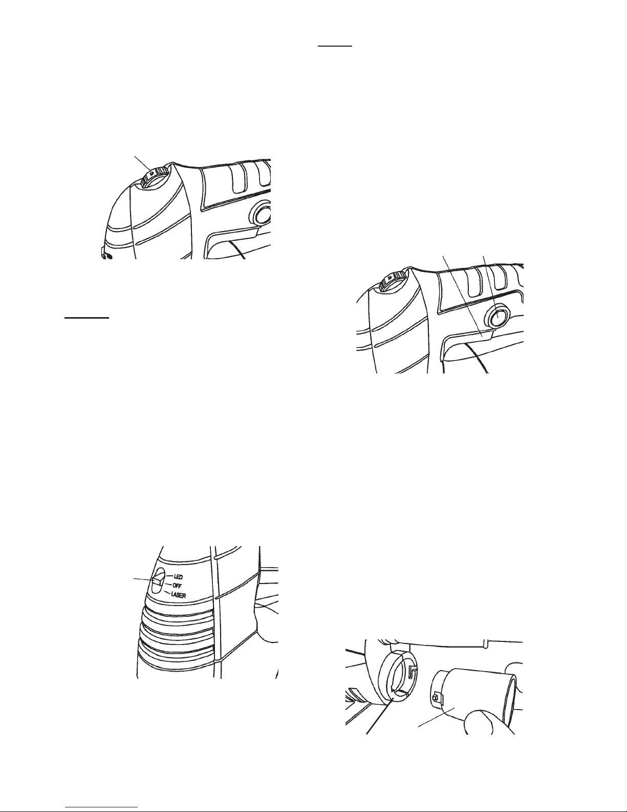
1. The Jigsaw comes with four cutting modes
(three cutting settings and 1 straight cutting
mode). To change cutting mode, adjust the
Orbital Mode Lever (12). See Figure 2, below.
Figure 2
Orbital Mode Lever (12)
2. The settings are:
a. I = Straight line cutting (for
plastics and mild steel)
b. II = Small orbit (for aluminum
and hard wood)
c. III = Medium orbit (for wood, plywood
and fast cutting of aluminum)
d. IV = Large orbit (for fast cutting
wood and plywood)
Page 9
Page 9For technical questions, please call 1-800-444-3353.SKU 68821
Adjusting Jigsaw Speed
1. The Jigsaw’s speed can be adjusted between
500 and 3,000 strokes per minutes.
2. To adjust speed, turn the Speed Switch from
1 (the slowest speed) to 6 (the fastest speed).
See Figure 3, below.
Figure 3
Speed Switch
3. Use higher speeds to cut workpieces faster.
NOTICE: Refer to the Blade Selection
chart on page 7 to verify you are using the
correct speed with the appropriate blade.
Otherwise blade damage can occur.
General Operating Instructions
1. Plug the Power Cord into the nearest
120 volt, grounded, electrical outlet.
2. Position the saw blade of the Jigsaw about
1/2” from the beginning cut line on the
workpiece. Do not allow the saw blade
to come in contact with the workpiece.
3. Turn the Laser Switch (46) to its “LASER”
position, and align the laser beam with the cut
line on the workpiece. See Figure 4, below.
Figure 4
Laser
Switch
(46)
NOTE: The Jigsaw is equipped with
both a Laser Guide and an LED light.
However, both cannot be used at the same time.
The Laser Switch can only be set in the
Laser setting OR the LED light setting.
4. To turn off the Laser or LED, slide the
Laser Switch to the OFF position.
5. Squeeze the Trigger (16) to turn on the
Jigsaw. If operating the Jigsaw for an
extended period of time, depress the Trigger
Lock (located above the Power Switch) to
lock the Trigger in its “ON” position.
See Figure 5, below.
Figure 5
Trigger
(16)
Trigger
Lock
6. Allow the Saw Blade to stroke at full speed
before slowly feeding it into the workpiece.
7. Make sure to hold the Jigsaw rmly
with both hands to avoid kickback.
Then, nish making the cut.
Dust Chute and Dust Blower
1. The Jigsaw is supplied with a Dust Chute
adapter for a vacuum. It is attached
to the Dust Chute Connector located
at the back end of the housing.
2. To fasten the Dust Chute (sold separately)
in place, align the pins on Dust Chute with
slots in Connector. Push Dust Chute in and
turn clockwise to lock. See Figure 6, below.
Dust
Chute
Connector
Figure 6
Page 10
Page 10 For technical questions, please call 1-800-444-3353. SKU 68821
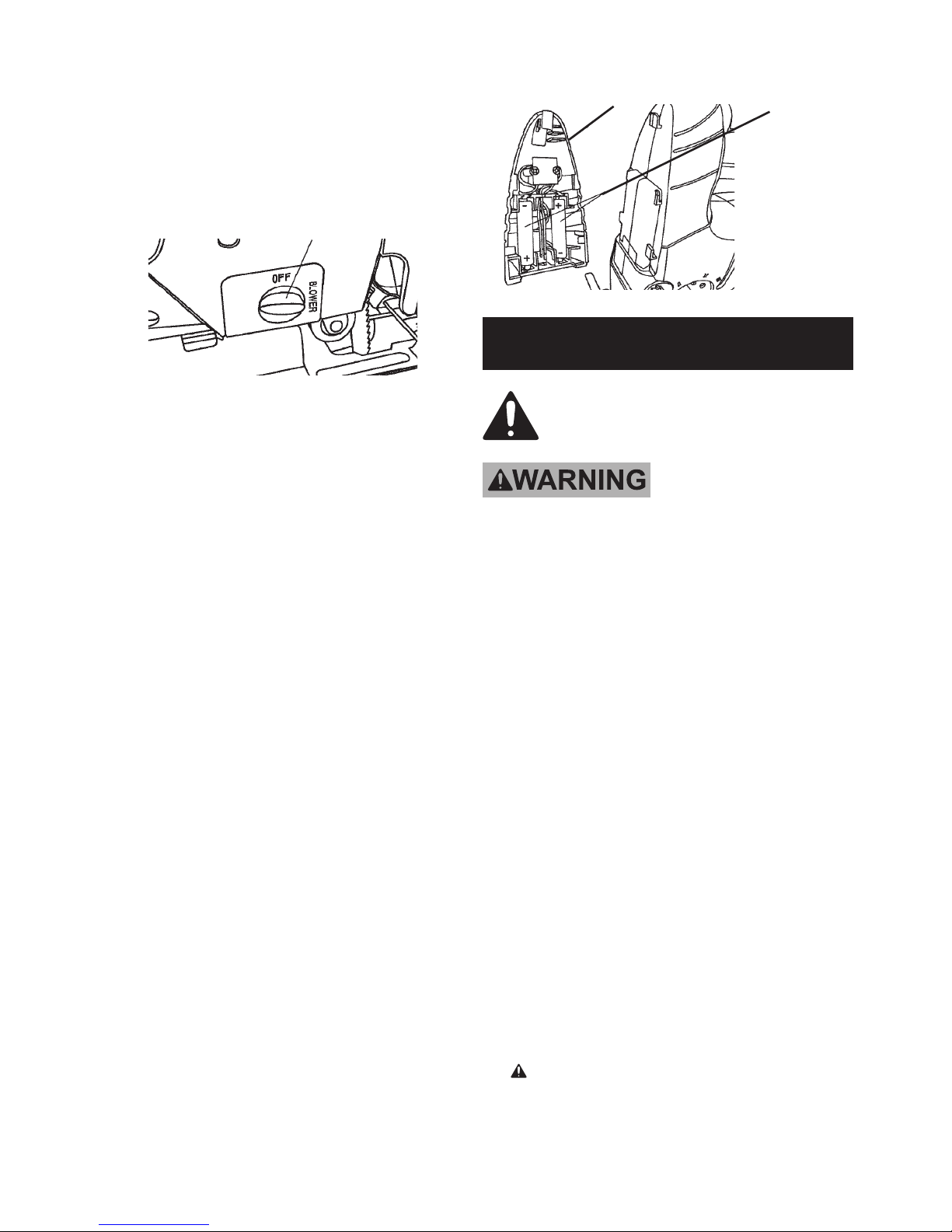
3. To clear dust from accumulating along
the cut line, use the Dust Blower to
blow a stream of air onto workpiece.
4. To activate, turn the Dust Blower switch
to the on (horizontal) position. To turn
it off, turn the switch back to the off
(vertical) position. See Figure 7, below.
Figure 7
Dust Blower Switch
Bevel and Metal Cutting
1. Use the included Hex Key to loosen the
Cap Screw (24) on the bottom of the
Base Plate (22). Tilt the base, allowing
for bevel cuts between 0 and 45°.
2. Retighten the Cap Screw once the
desired angle is reached.
3. For metal cutting, be sure to use a coolant
such as cutting oil during use. Failure
to add coolant will lead to greater blade
wear. If desired, grease the underside of
the workpiece in place of adding coolant.
4. When nished with the Jigsaw, unlock and
release the Trigger to stop the Jigsaw. Wait
until the Saw Blade stops completely. Turn
the Laser Switch to its “OFF” position. Then,
remove the Jigsaw from the workpiece.
5. To prevent accidents disconnect the
power cord after use. Clean, then store
the tool indoors out of children’s reach.
Replacing Laser Batteries
1. Push Laser Shell up and lift off of housing.
2. Remove the two AAA batteries from the inside
of the Laser Shell (45) and replace with two
new AAA batteries. See Figure 8, above right.
CAUTION! Position batteries
according to indicated polarity.
3. Slide Laser Shell back onto housing.
Figure 8
Batteries
Laser Shell (45)
Maintenance and Servicing
Procedures not specically explained
in this manual must be performed
only by a qualied technician.
TO PREVENT SERIOUS INJURY
FROM ACCIDENTAL OPERATION:
Unlock and release Trigger and
unplug tool from its electrical outlet
before performing any inspection,
maintenance, or cleaning procedures.
TO PREVENT SERIOUS INJURY
FROM TOOL FAILURE: Do not use
damaged equipment. If abnormal noise
or vibration occurs, have the problem
corrected before further use.
Cleaning, Maintenance,
and Lubrication
1. BEFORE EACH USE, inspect the general
condition of the tool. Check for loose
hardware, misalignment or binding of
moving parts, cracked or broken parts,
damaged electrical wiring, and any other
condition that may affect its safe operation.
2. Inspect the Saw Blade. Replace with
a new Saw Blade when needed.
3. AFTER USE, wipe external surfaces
of the tool with clean cloth.
4. WARNING! If the supply cord of this
power tool is damaged, it must be replaced
only by a qualied service technician.
Page 11
Page 11For technical questions, please call 1-800-444-3353.SKU 68821
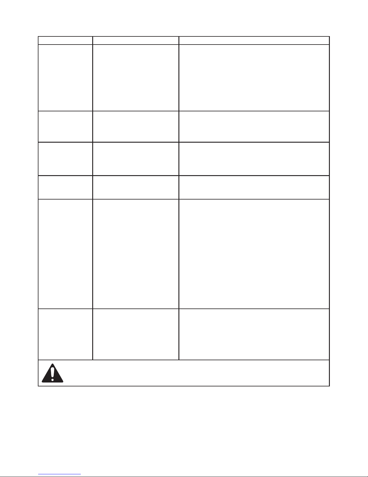
Troubleshooting
Problem Possible Causes Likely Solutions
Tool will not start. 1. Cord not connected.
2. No power at outlet.
3. Internal damage or wear.
(Carbon brushes or
switch, for example.)
1. Check that cord is plugged in.
2. Check power at outlet. If outlet is unpowered,
turn off tool and check circuit breaker.
If breaker is tripped, make sure circuit is right
capacity for tool and circuit has no other loads.
3. Have technician service tool.
Tool operates
slowly.
Extension cord too long
or wire size too small.
Eliminate use of extension cord.
If an extension cord is needed, use shorter/
heavier gauge cord. See Extension Cords
in Grounding section on page 5.
Performance
decreases
over time.
1. Accessory dull
or damaged.
2. Carbon brushes
worn or damaged.
1. Keep cutting accessories sharp.
Replace as needed.
2. Have qualied technician replace brushes.
Excessive noise
or rattling.
Internal damage or wear.
(Carbon brushes or
bearings, for example.)
Have technician service tool.
Overheating. 1. Forcing tool to
work too fast.
2. Accessory misaligned.
3. Accessory dull
or damaged.
4. Blocked motor
housing vents.
5. Motor being strained by
long or small diameter
extension cord.
1. Allow tool to work at its own rate.
2. Check and correct accessory to
fence and/or table alignment.
3. Keep cutting accessories sharp.
Replace as needed.
4. Wear ANSI-approved safety goggles and
NIOSH-approved dust mask/respirator while
blowing dust out of motor using compressed air.
5. Eliminate use of extension cord. If an extension
cord is needed, use one with the proper
diameter for its length and load. See Extension
Cords in Grounding section on page 5.
Laser Guide will
not illuminate.
1. Laser Switch is off
or set to LED.
2. Laser opening is
dirty or blocked.
3. Laser damaged.
1. Turn Laser Switch on to LASER setting.
2. Turn Laser Switch to it’s OFF position.
Then clean the laser opening.
3. Have a qualied service technician
check the tool for internal damage.
Follow all safety precautions whenever diagnosing or servicing the tool.
Disconnect power supply before service.
Page 12

Page 12 For technical questions, please call 1-800-444-3353. SKU 68821
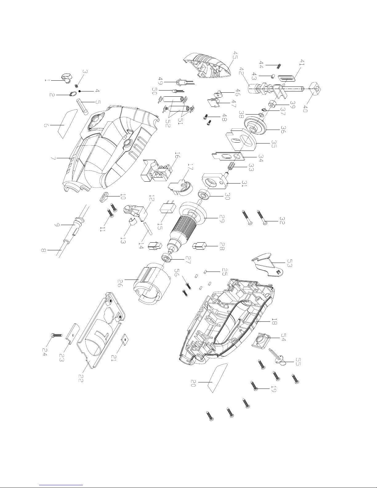
Part Description
1 Knob
2 Circlip Φ10
3 Spring Φ3.9×5.5
4 Steel Ball
5 Pin
6 Label
7 Left Housing
8 Power Cord
9 Power Cord Sleeve
10 Cord Clip
11 Screw (M4.2×16)
12 Orbital Mode Lever
13 Spring Lamination
14 Fixed Pin
15 Capacitor
16 Trigger
17 Circuit Board
18 Right Housing
19 Screw (M4.2×20)
20 Label
21 Nut (M4)
22 Base Plate
23 Washer Board
24 Cap Screw (M6)
25 Needle (Φ3×6.5)
26 Field
27 Bearing 607
28 Brush
29 Armature
Part Description
30 Bearing (608)
31 Center Support
32 Screw (M4.2×32)
33 Needle Bearing (0613.5)
34 Balance Patch
35 Balance Frame
36 Gear
37 Spring (Φ5.5)
38 Washer (Φ6×0.5)
39 Directive Wheel
40 Bearing
41 Positive Plate
42 Blade Holder Shaft
43 Spring Housing
44 Spring (Φ3.9×10)
45 Laser Shell
46 Laser Switch
47 Circuit Board
48 Screw (M3×8)
49 Laser
50 LED Lamp
51 Positive Electrode
52 Laser Batteries (not included)
53 Blade Cover
54 Setting Board
55 Adjustment Knob
56 Screw (M2×8)
57 Hex Key (not shown)
Parts List and Assembly Diagram
PLEASE READ THE FOLLOWING CAREFULLY
THE MANUFACTURER AND/OR DISTRIBUTOR HAS PROVIDED THE PARTS LIST AND ASSEMBLY DIAGRAM
IN THIS MANUAL AS A REFERENCE TOOL ONLY. NEITHER THE MANUFACTURER OR DISTRIBUTOR
MAKES ANY REPRESENTATION OR WARRANTY OF ANY KIND TO THE BUYER THAT HE OR SHE IS
QUALIFIED TO MAKE ANY REPAIRS TO THE PRODUCT, OR THAT HE OR SHE IS QUALIFIED TO REPLACE
ANY PARTS OF THE PRODUCT. IN FACT, THE MANUFACTURER AND/OR DISTRIBUTOR EXPRESSLY
STATES THAT ALL REPAIRS AND PARTS REPLACEMENTS SHOULD BE UNDERTAKEN BY CERTIFIED AND
LICENSED TECHNICIANS, AND NOT BY THE BUYER. THE BUYER ASSUMES ALL RISK AND LIABILITY
ARISING OUT OF HIS OR HER REPAIRS TO THE ORIGINAL PRODUCT OR REPLACEMENT PARTS
THERETO, OR ARISING OUT OF HIS OR HER INSTALLATION OF REPLACEMENT PARTS THERETO.
Parts List
Record Product’s Serial Number Here:
Note: If product has no serial number, record month and year of purchase instead.
Note: Some parts are listed and shown for illustration purposes only,
and are not available individually as replacement parts.
Page 13
Page 13For technical questions, please call 1-800-444-3353.SKU 68821
Assembly Diagram
Page 14

Page 14 For technical questions, please call 1-800-444-3353. SKU 68821
90 Day Warranty
Harbor Freight Tools Co. makes every effort to assure that its products meet high quality
and durability standards, and warrants to the original purchaser that this product is free from
defects in materials and workmanship for the period of 90 days from the date of purchase. This
warranty does not apply to damage due directly or indirectly, to misuse, abuse, negligence or
accidents, repairs or alterations outside our facilities, criminal activity, improper installation,
normal wear and tear, or to lack of maintenance. We shall in no event be liable for death,
injuries to persons or property, or for incidental, contingent, special or consequential damages
arising from the use of our product. Some states do not allow the exclusion or limitation of
incidental or consequential damages, so the above limitation of exclusion may not apply to
you. THIS WARRANTY IS EXPRESSLY IN LIEU OF ALL OTHER WARRANTIES, EXPRESS
OR IMPLIED, INCLUDING THE WARRANTIES OF MERCHANTABILITY AND FITNESS.
To take advantage of this warranty, the product or part must be returned to us with
transportation charges prepaid. Proof of purchase date and an explanation of the complaint
must accompany the merchandise. If our inspection veries the defect, we will either repair or
replace the product at our election or we may elect to refund the purchase price if we cannot
readily and quickly provide you with a replacement. We will return repaired products at our
expense, but if we determine there is no defect, or that the defect resulted from causes not
within the scope of our warranty, then you must bear the cost of returning the product.
This warranty gives you specic legal rights and you may also have other rights which vary from
state to state. thehehehehehehehehehehhehehehehehehehehehehheheheheheheheheh
Page 15

3491 Mission Oaks Blvd. • PO Box 6009 • Camarillo, CA 93011 • (800) 444-3353
 Loading...