

Page 1
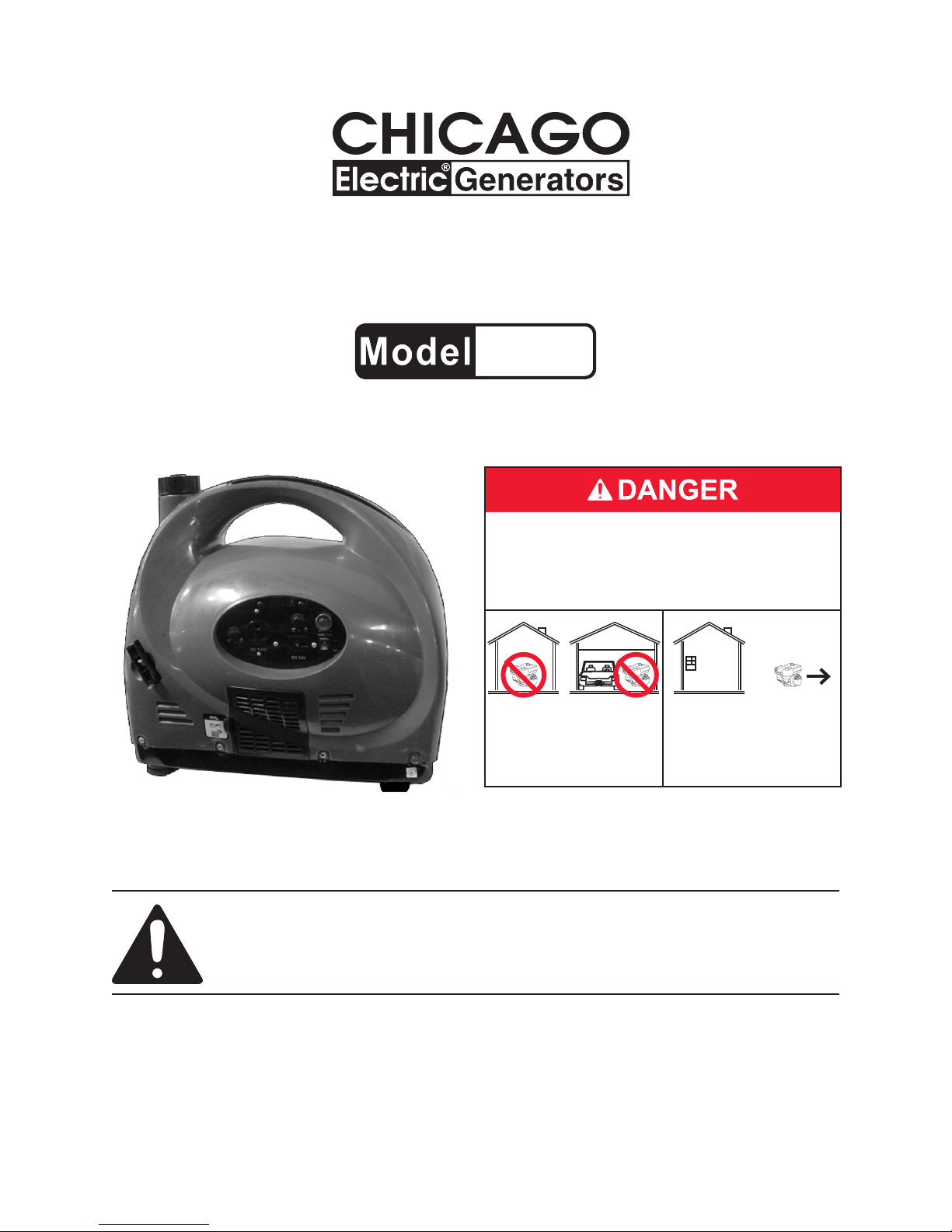
CAMPING GENERATOR
1300 WATT
66523
SET UP, OPERATING, AND SERVICING
INSTRUCTIONS
Using an engine indoors CAN KILL YOU IN
MINUTES.
Engine exhaust contains carbon monoxide.
This is a poison you cannot see or smell.
NEVER use inside
a home or garage,
EVEN IF doors and
windows are open.
Distributed exclusively by Harbor Freight Tools®.
3491 Mission Oaks Blvd., Camarillo, CA 93011
Visit our website at: http://www.harborfreight.com
Only use OUTSIDE
and far away from
windows, doors, and
vents.
Read this material before using this product.
Failure to do so can result in serious injury.
SAVE THIS MANUAL.
Copyright© 2008 by Harbor Freight Tools®. All rights reserved. No portion of this manual or any artwork
contained herein may be reproduced in any shape or form without the express written consent of
Harbor Freight Tools. Diagrams within this manual may not be drawn proportionally. Due to continuing
improvements, actual product may differ slightly from the product described herein. Tools required for
assembly and service may not be included.
For technical questions or replacement parts, please call 1-800-444-3353.
Page 2

TABLE OF CONTENTS
IMPORTANT SAFETY INFORMATION............................................................................3
SET UP PRECAUTIONS..................................................................................................3
OPERATING PRECAUTIONS..........................................................................................4
SERVICE PRECAUTIONS...............................................................................................5
GENERATOR PRECAUTIONS........................................................................................6
BASIC ENGINE SPECIFICATIONS.................................................................................7
UNPACKING....................................................................................................................7
OPERATING INSTRUCTIONS.........................................................................................7
TECHNICAL SPECIFICATIONS....................................................................................12
SERVICING. ..................................................................................................................12
TROUBLESHOOTING - ENGINE..................................................................................15
TROUBLESHOOTING - GENERATOR..........................................................................17
PARTS LIST....................................................................................................................18
ASSEMBLY DIAGRAM..................................................................................................19
PARTS LIST - ENGINE..................................................................................................20
ASSEMBLY DIAGRAM - ENGINE.................................................................................21
WIRING DIAGRAM........................................................................................................22
WARRANTY INFORMATION.........................................................................................23
PLEASE READ THE FOLLOWING...............................................................................24
SKU 66523 For technical questions, please call 1-800-444-3353. Page 2
Page 3
SAVE THIS MANUAL
Keep this manual for the safety warnings and precautions, assembly, operating,
inspection, maintenance and cleaning procedures. Write the product’s serial number
in the back of the manual (or month and
year of purchase if product has no number). Keep this manual and the receipt in
a safe and dry place for future reference.
IMPORTANT SAFETY
INFORMATION
In this manual, on the labeling,
and all other information
provided with this product:
This is the safety alert
symbol. It is used to alert
you to potential personal
injury hazards. Obey all
safety messages that
follow this symbol to avoid
possible injury or death.
NOTICE is used to
address practices
not related to personal injury.
CAUTION, without
the safety alert
symbol, is used to address
practices not related to
personal injury.
WARNING! Read all instructions.
Failure to follow all instructions
listed below may result in re,
serious injury and/or DEATH.
The warnings and precautions
discussed in this manual cannot
cover all possible conditions and
situations that may occur. It must
be understood by the operator that
common sense and caution are
factors which cannot be built into
this product, but must be supplied
by the operator.
SAVE THESE INSTRUCTIONS
SET UP PRECAUTIONS
DANGER indicates
a hazardous
situation which, if not
avoided, will result in death or
serious injury.
WARNING
indicates a
hazardous situation which, if
not avoided, could result in
death or serious injury.
CAUTION, used
with the safety
alert symbol, indicates a
hazardous situation which, if
not avoided, could result in
minor or moderate injury.
SKU 66523 For technical questions, please call 1-800-444-3353. Page 3
Gasoline fuel and fumes are amma-1.
ble, and potentially explosive. Use
proper fuel storage and handling procedures. Do not store fuel or other
ammable materials nearby.
Have multiple ABC class re extin-2.
guishers nearby.
Operation of this equipment may cre-3.
ate sparks that can start res around
dry vegetation.
The operator should contact local re
agencies for laws or regulations relat-
ing to re prevention requirements.
Set up and use only on a at, level, 4.
well-ventilated surface.
Page 4
Wear ANSI-approved safety goggles 5.
and heavy-duty work gloves during
set up.
Use only oil and fuel recommended 6.
in the “Specications” section of this
manual.
OPERATING PRECAUTIONS
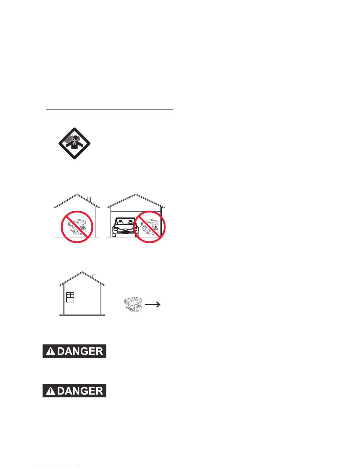
1. CARBON MONOXIDE
HAZARD
Using an engine indoors
CAN KILL YOU IN
MINUTES.
Engine exhaust contains carbon
monoxide. This is a poison you
cannot see or smell.
the Generator when the machine is
running.
Keep all people (except the operator) 4.
a minimum of six feet from the Generator during operation.
Do not transport the Generator with 5.
the Engine running.
Do not sit or stand on this machine.6.
Do not tilt the machine while the En-7.
gine is running.
Do not leave the Generator unattend-8.
ed when it is running. Turn off the
Engine before leaving the area.
Wear ANSI-approved safety goggles, 9.
hearing protection, and heavy duty
work gloves during use.
NEVER use inside a home or garage,
EVEN IF doors and windows are
open.
Only use OUTSIDE and far away
from windows, doors, and vents.
2. Keep all safety
guards in place and
in proper working order at all times.
3. NEVER place
ngers, hands, or
body near the Generator when it is
running. Do not lean or reach over
People with pacemakers should 10.
consult their physician(s) before
use. Electromagnetic elds in close
proximity to a heart pacemaker could
cause pacemaker interference or
pacemaker failure. Caution is necessary when near the engine’s magneto
or recoil starter.
Use only accessories that are recom-11.
mended by Harbor Freight Tools for
your model. Accessories that may be
suitable for one piece of equipment
may become hazardous when used
on another piece of equipment.
Do not operate in explosive atmo-12.
spheres, such as in the presence of
ammable liquids, gases, or dust.
Gasoline-powered engines may ignite
the dust or fumes.
Stay alert, watch what you are doing 13.
and use common sense when operating this piece of equipment. Do not
use this piece of equipment while
SKU 66523 For technical questions, please call 1-800-444-3353. Page 4
Page 5

tired or under the inuence of drugs,
alcohol or medication.
Do not overreach. Keep proper foot-14.
ing and balance at all times. This enables better control of the equipment
in unexpected situations.
Dress properly. Do not wear loose 15.
clothing or jewelry. Keep hair, clothing and gloves away from moving
parts. Loose clothes, jewelry or long
hair can be caught in moving parts.
als as per any local, state, or federal
codes and regulations. Store oil rags
in a bottom-ventilated, covered, metal
container.
Before use, check for misalignment 23.
or binding of moving parts, breakage
of parts, and any other condition that
may affect the equipment’s operation.
If damaged, have the equipment
serviced before using. Many ac-
cidents are caused by poorly maintained equipment.
Parts, especially exhaust system 16.
components, get very hot during use.
Stay clear of hot parts.
Do not cover the Generator during 17.
operation.
Keep the equipment, Engine, and 18.
surrounding area clean at all times.
Use the equipment, accessories, etc., 19.
in accordance with these instructions
and in the manner intended for the
particular type of equipment, taking
into account the working conditions
and the work to be performed. Use
of the equipment for operations different from those intended could result
in a hazardous situation.
Do not operate the equipment with 20.
known leaks in the Engine’s fuel
system.
This product contains or, when used, 21.
produces a chemical known to the
State of California to cause cancer
and birth defects or other reproductive harm. (California Health & Safety
Code § 25249.5, et seq.)
When spills of fuel or oil occur, they 22.
must be cleaned up immediately.
Dispose of uids and cleaning materi-
Use the correct equipment for the 24.
application. Do not modify the equipment and do not use the equipment
for a purpose for which it is not intended.
SERVICE PRECAUTIONS
Before service, maintenance, or 1.
cleaning:
Turn the Power Switch of the En-a.
gine to its “OFF” position.
Allow the Engine to completely b.
cool.
Then, remove the Spark Plug.c.
Keep all safety guards in place and in 2.
proper working order. Safety guards
include mufer, air cleaner, mechanical guards, and heat shields, among
other guards.
Do not alter or adjust any part of the 3.
equipment or its Engine that is sealed
by the manufacturer or distributor.
Only a qualied service technician
may adjust parts that may increase or
decrease governed Engine speed.
Wear ANSI-approved safety goggles 4.
and heavy duty work gloves during
service.
SKU 66523 For technical questions, please call 1-800-444-3353. Page 5
Page 6

Maintain labels and nameplates on 5.
the equipment. These carry important information. If unreadable or
missing, contact Harbor Freight Tools
for a replacement.
Have the equipment serviced by a 6.
qualied repair person using only
identical replacement parts. This will
ensure that the safety of the equipment is maintained. Do not attempt
any service or maintenance procedures not explained in this manual
or any procedures that you are uncertain about your ability to perform
safely or correctly.
Store equipment out of the reach of 7.
children.
Follow scheduled Engine and equip-8.
ment maintenance.
Refueling Precautions:9.
GENERATOR
PRECAUTIONS
Set Up:
Do not connect the Generator directly 1.
into a home’s utility electrical line. Do
not plug this Generator into an outlet
in the home. Connecting a generator
directly to a utility power supply can
“back feed” along the power lines and
kill or injure utility workers working on
the lines.
All connections and conduits from 2.
the Generator to the load must only
be installed by trained and licensed
electricians, and in compliance with
all relevant local, state, and federal
electrical codes and standards, and
other regulations where applicable.
Do not smoke, or allow sparks, •
ames, or other sources of ignition
around the equipment, especially
when refuelling.
Do not rell the Fuel Tank while the •
engine is running or hot.
Do not ll Fuel Tank to the top. •
Leave a little room for the fuel to
expand as needed.
Refuel in a well-ventilated area only.•
SAVE THESE INSTRUCTIONS.
The Generator must be earth-ground-3.
ed in accordance with all relevant
electrical codes and standards before
operation.
A 10-gauge copper wire should be •
used to connect the ground terminal of the Generator to a grounding
rod. A wire that is too thin may not
provide sufcient electrical current
carrying capacity to be an adequate
ground path.
The other end of the ground wire •
must be securely fastened to an
approved ground source. Refer to
local regulations for ground source
information. If unsure of regulations
or procedures, obtain assistance
from a licensed or certied electrician.
SKU 66523 For technical questions, please call 1-800-444-3353. Page 6
Insulate all connections and discon-4.
nected wires.
Page 7

Connect the Generator only to a load 5.
or electrical system (120 VAC or
12 VDC) that is compatible with the
electrical characteristics and rated
capacities of the Generator.
Set up the Generator outdoors in a 6.
well-ventilated, dry area, away from
building air intakes. The Generator should be protected from direct
exposure to rain and snow. Do not
set up the Generator on a conductive
surface such as a metal deck.
Operation:
Do not attempt to connect or discon-1.
nect load connections while standing
in water, or on wet or soggy ground.
BASIC SPECIFICATIONS
Fuel
Type
Capacity 1.3 Gallons
Type SAE 10W-30
Engine Oil
Capacity 13.5 Ounces
Note: Additional specications found in
the TECHNICAL ENGINE SPECIFICATIONS chart in this manual.
The emission control system for
this Generator’s Engine is warranted for
standards set by the U.S. Environmental
Protection Agency and by the California Air
Resources Board (also known as CARB).
For warranty information, refer to the last
pages of this manual.
91+ octane unleaded
gasoline
Do not touch electrically energized 2.
parts of the Generator and interconnecting cables or conductors with any
part of the body, or with any
non-insulated conductive object.
Use only Class BC or Class ABC re 3.
extinguishers on electrical res.
Do not overload the Generator. 4.
Overloading can cause res in the
electrical cords, in addition to Generator and appliance damage.
Service:
Keep all electrical equipment clean 1.
and dry. Replace any wiring where
the insulation is cracked, cut, abraded, or otherwise degraded. Replace
terminals that are worn, discolored, or
corroded. Keep terminals clean and
tight.
At high altitudes, the engine’s carburetor, governor, and any other parts that
control the fuel-air ratio will need to be
adjusted by a qualied mechanic to allow
efcient high-altitude use and to prevent
damage to the engine and any other devices used with this product.
UNPACKING
When unpacking, check to make sure
that the item is intact and undamaged. If
any parts are missing or broken, please
call Harbor Freight Tools at the number
shown on the cover of this manual as soon
as possible.
OPERATING INSTRUCTIONS
Read the ENTIRE IMPORTANT
SAFETY INFORMATION
section at the beginning of this
manual including all text under
SKU 66523 For technical questions, please call 1-800-444-3353. Page 7
Page 8
subheadings therein before set
up or use of this product.
TO PREVENT
SERIOUS INJURY:
Operate only with proper spark
arrestor installed. Operation of
this equipment may create
sparks that can start res
around dry vegetation.
The operator should contact
local re agencies for laws or
regulations relating to re
prevention requirements.
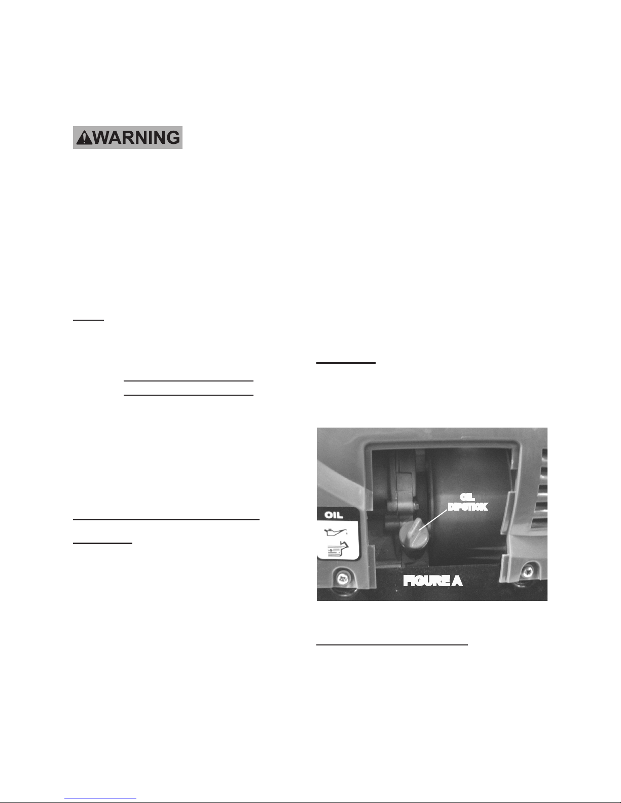
Reinsert the Dipstick completely 2.
(but do not screw it in) and remove
it to check the oil level. The oil level
should be between the HIGH and
LOW marks on the Dipstick.
(See Figure A.) Note: Inspect the
O-Ring at the neck of the Dipstick. If
cracked, torn or damaged it must be
replaced.
If the oil level is below the low mark 3.
add the appropriate type of oil until
the oil level is between the high and
the low marks.
Oil type and capacity:
SAE 10W-30 / 13.5 Ounces
Note: For additional information regarding
the parts listed in the following pages,
refer to the Assembly Diagram near
the end of this manual.
Starting the Engine
Inspect the Generator looking
for damaged, loose, and
missing parts before set up and
starting. If any problems are
found, do not use the machine
until properly repaired.
Checking and Filling Engine Oil:
CAUTION! Your Warranty is VOID if the
Engine’s Crankcase is not properly
lled with oil before each use. Before
each use, check the oil level. Do not
run the Engine with low or no engine
oil. Running the Engine with no or
low engine oil WILL permanently
damage the Engine.
Replace the Oil Dipstick. 4.
(See Figure A.)
CAUTION! Do not run the Engine with too
little or too much oil. The Engine will
be permanently damaged.
OIL
DIPSTICK
FIGURE A
Checking and Filling Fuel:
Remove the Engine’s Dipstick and 1.
wipe it off with a clean rag.
(See Figure A.)
SKU 66523 For technical questions, please call 1-800-444-3353. Page 8
Allow engine to cool down prior to re-1.
fueling. Remove the Fuel Cap (14)
and check the fuel level.
(See Figure B, next page.)
Page 9
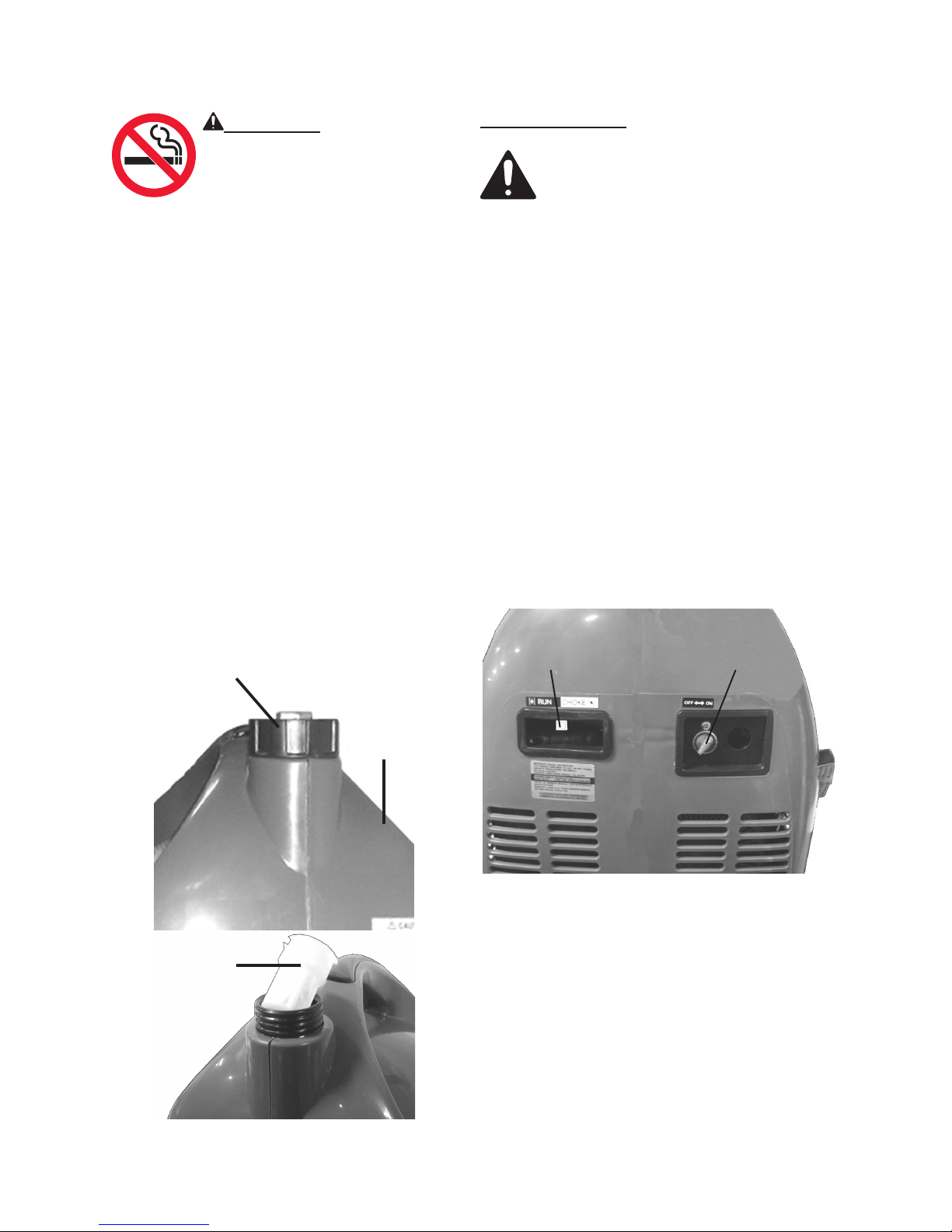
WARNING! TO PREVENT
SERIOUS INJURY FROM
FIRE:
Fill the Fuel Tank (20) in a
well-ventilated area away from ignition or spark sources. Do not smoke.
To ll the Fuel Tank (20), rst wipe off 2.
the Fuel Tank Cap (14) and the surrounding area. (See Figure B.)
Unscrew, and remove the Fuel Tank 3.
Cap (14). (See Figure B.)
Remove the Filter Basket (19) and 4.
remove any dirt and debris. Then
replace the Filter Basket.
(See Figure B.)
Fill the Fuel Tank (20) to about 1 inch 5.
under the ll neck of the Tank with the
unleaded gasoline mixture.
(See Figure B.)
Start Procedure:
Before starting the Engine:
Inspect the equipment and En-a.
gine.
Fill the Engine with the proper b.
amount and type of fuel and oil.
(See Figures A and B.)
NOTE: Only after the Genera-c.
tor has stabilized and is running
smoothly should an appliance
or tool be plugged into the AC
Outlet of the Generator.
Turn the Engine Fuel Lever to its “ON” 1.
position. (See Figure C.)
Turn the Engine Choke Lever to its 2.
“CHOKE” position. Set the Choke Lever in the “RUN” position when start-
ing a warm Engine.
(See Figure C.)
Then replace the Fuel Tank Cap (14). 6.
(See Figure B.)
FUEL TANK
CAP (14)
FIGURE B
FILTER
BASKET
(19)
FUEL TANK
(20)
FIGURE C
CHOKE LEVER
FUEL LEVER
Then turn the Engine Power Switch to 3.
its “ON” position.
(See Figure D, next page.)
SKU 66523 For technical questions, please call 1-800-444-3353. Page 9
Page 10
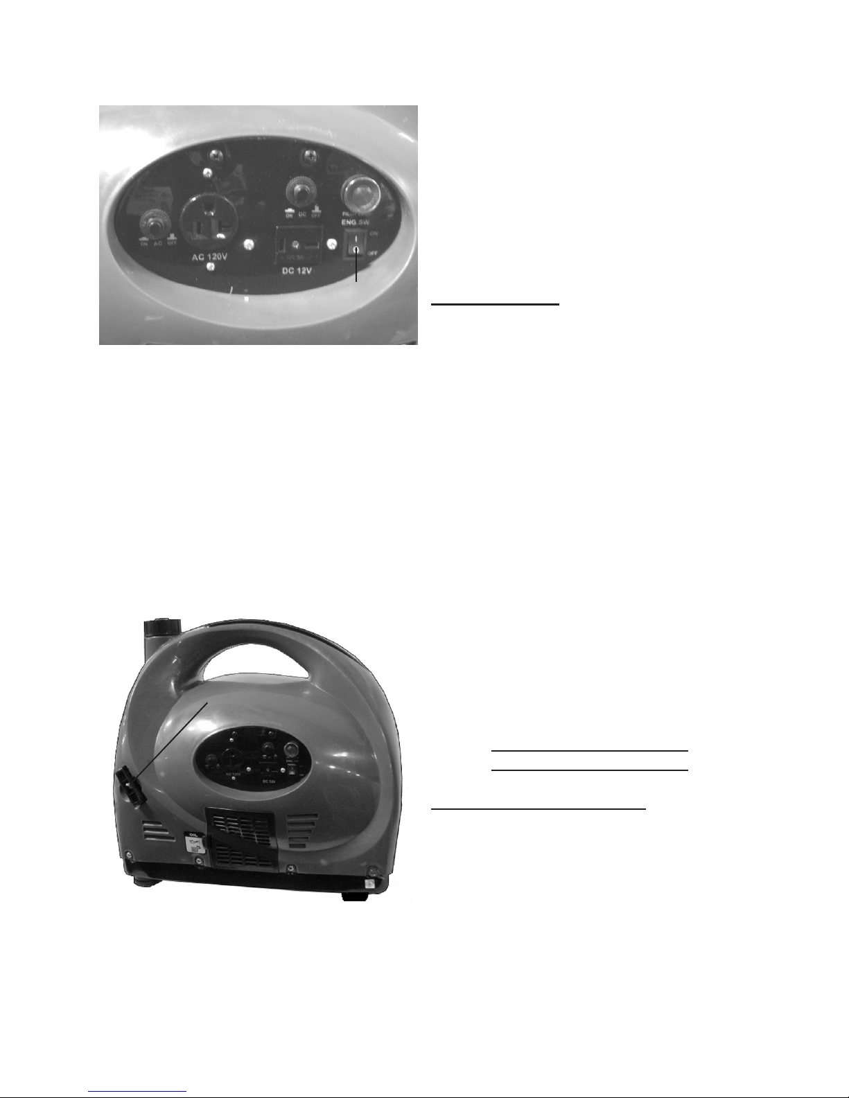
FIGURE D
After the Engine starts and warms up, 5.
slowly move the Choke Lever to its
“RUN” position. (See Figure C.)
IMPORTANT: Allow the Engine to 6.
run at no load until warm (approx. 3
minutes) after each start-up to allow
the Engine to stabilize.
POWER
SWITCH
Grasp the Starter Handle and pull 4.
slowly until resistance is felt. While
holding the Handle, allow the Starter
Rope to rewind slowly. Then, pull the
Starter Handle with a rapid, full arm
stroke. Once again while holding
the Handle, allow the Rope to rewind
slowly. Repeat as necessary, until
the Engine starts. (See Figure E.)
FIGURE E
STARTER HANDLE
Break-in Period:
Breaking-in the Engine will help to 1.
ensure proper equipment and Engine
operation, and will extend the Engine’s lifespan. The warranty is void
if the Engine is not broken in properly.
The rst 25 hours of operation is the
break-in period.
During this time frame, DO NOT •
exceed 75% of the Generator’s load
limit. In other words, the maximum
load during this break-in period
should be no more than 700 watts.
After the rst 25 hours of use:•
Change the engine oil.•
Under normal operating conditions
subsequent maintenance follows the
schedule explained in the MAINTENANCE AND SERVICING section.
SKU 66523 For technical questions, please call 1-800-444-3353. Page 10
Equipment Operation
Load And Circuit Breakers:
The total combined load through any 1.
combination of outlets on the Generator must not exceed the rated power
(1300 watts peak; or 1,000 watts
rated) of the unit.
Always reduce the load if the AC 2.
Circuit Breaker or DC Circuit Breaker
trips off. Once the load is reduced,
Page 11
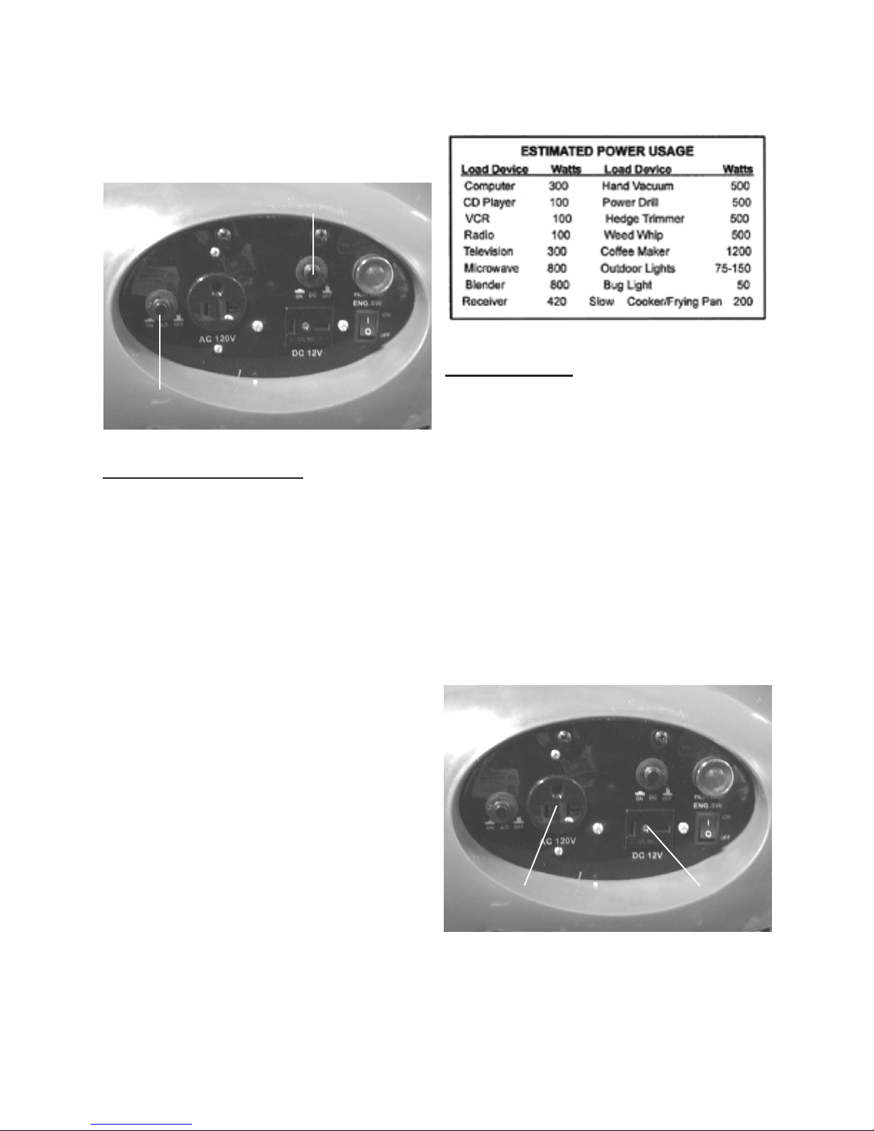
press the appropriate Breaker to reset
the Generator and continue operation.
(See Figure F.)
FIGURE G
FIGURE F
AC
CIRCUIT BREAKER
CIRCUIT BREAKER
DC
Calculating Power Draw:
Power draw can be calculated by mul-1.
tiplying volts and amps. The resulting
number is wattage.
Never exceed the rated maximum •
wattage (1300) for the Generator or
either outlet.
Refer to appliance/tool owner’s •
manuals to determine the wattage of
electrical load devices.
AC Application:
Allow the Engine to run at no load 1.
until warm (approx. 3 minutes) after
each start-up to allow the Engine to
stabilize.
Plug the power cord of the 120 volt 2.
appliance/tool into the 120 volt AC
Outlet on the Generator.
(See Figure H.)
When nished using the appliance/3.
tool, unplug its power cord from the
AC Outlet on the Generator.
(See Figure H.)
Long power cords and extension •
cords draw additional power. Keep
cord length at a minimum.
(See Figure G.)
SKU 66523 For technical questions, please call 1-800-444-3353. Page 11
FIGURE H
AC OUTLET
DC OUTLET
Page 12
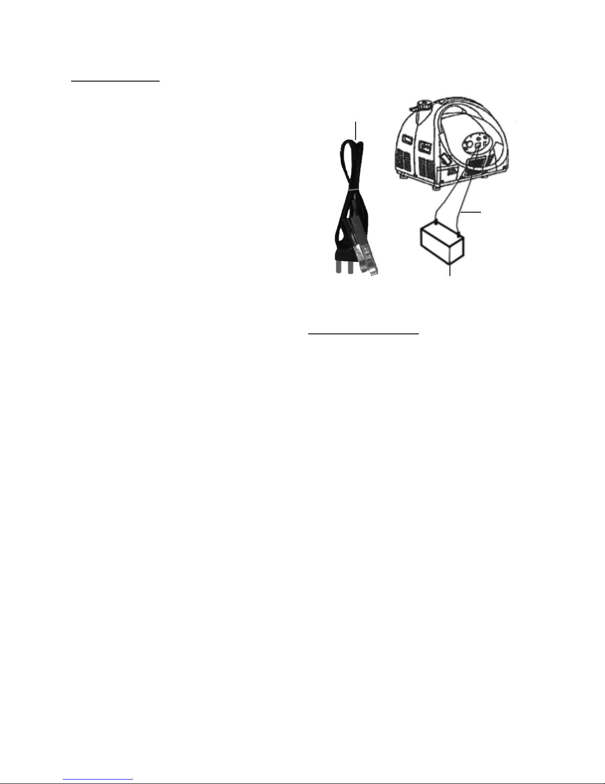
DC Application:
Allow the Engine to run at no load 1.
until warm (approx. 3 minutes) after
each start-up to allow the Engine to
stabilize.
The 12 volt DC Outlet is designed for 2.
charging a 12 volt DC battery only.
(See Figure H.)
FIGURE I
DC
OUTLET
CORDS
Plug the DC Outlet Cord provided 3.
into the DC Outlet on the Generator.
Connect the Positive (+) clamp of the 4.
DC Outlet Cord to the Positive (+)
terminal on the battery.
(See Figure I, next page.)
Connect the Negative (--) clamp of 5.
the DC Outlet Cord to the Negative
(--) terminal on the battery.
(See Figure I.)
When nished charging the battery, 6.
unplug the DC Outlet Cord from the
DC Outlet on the Generator. Then
disconnect the Cord clamps from the
battery. (See Figure I.)
If charing a DC battery on a vehicle, 7.
always clamp the negative wire of the
Generator to a good ground connection on the chassis.
12 VDC BATTERY
(NOT INCLUDED)
Generator Shut Off:
Remove all electrical load devices 1.
from the Generator.
Allow the Engine to run for approxi-2.
mately 1 minute with no electrical
load.
Turn Generator’s Power Switch to the 3.
“OFF” position.
(See Figure D.)
Turn the Fuel Lever to its “OFF” posi-4.
tion. (See Figure C.)
DC
OUTLET
CORDS
SKU 66523 For technical questions, please call 1-800-444-3353. Page 12
Allow the Generator to completely 5.
cool before storing.
Page 13
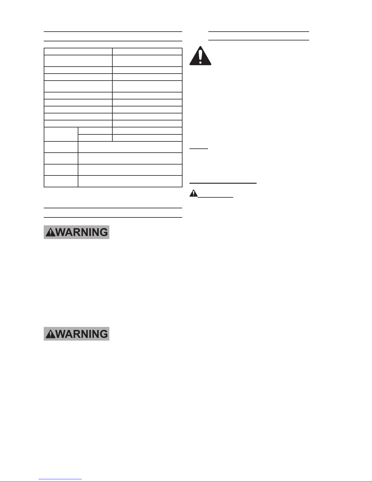
SPECIFICATIONS
Maintenance Procedures
Power Output 1,000W Rated, 1,300W Peak, 120VAC
Engine Type
Engine Starter Type Recoil Starter
Engine Power Rating 2.4 H.P.
Recommended Oil Type
and Capacity
Low Oil Protection Yes
Spark Plug Type / Gap F7RTC 0.028”~0.031”
Spark Plug Arrestor Present Yes
Armature Air Gap 0.0118”-0.0157”
Valve Clearance Intake=0.005”/Exhaust=0.006”
Fuel
Engine
Approvals
AC Receptacle
Type
DC Receptacle
Type
Engine Run Time
at 50% Load
Type 91+ octane unleaded gasoline
Capacity 1.3 Gallons
Meets with 2008 model year U.S. E.P.A. PH2
120 volt / 3-prong, grounded (Qty. 1)
2-20R / 8 Amps (Qty. 1)
12.0 Hours
Air Cooled, 4-Stroke, Single Cylinder,
Overhead Valves.
SAE 10W-30
13.5 Ounces
SERVICING
TO PREVENT
SERIOUS INJURY
FROM ACCIDENTAL
STARTING:
Turn the Power Switch of the
Engine to its “OFF” position,
wait for the Engine to cool,
and remove the Spark Plug
before performing any
inspection, maintenance, or
cleaning procedures.
TO PREVENT
SERIOUS INJURY
FROM EQUIPMENT FAILURE:
Do not use damaged
equipment. If abnormal noise,
vibration, or excess smoking
occurs, have the problem
corrected before further use.
Many maintenance procedures,
including those not detailed
in this manual, will need to
be performed by a qualied
technician for safety. If you
have any doubts about your
ability to safely service the
equipment or Engine, have a
qualied technician service the
equipment instead.
Note: Warranty is void if proper mainte-
nance and servicing procedures are
not followed.
Engine Oil Change:
CAUTION! Oil is very hot during opera-
tion and can cause burns. Wait for
Engine to cool before changing oil.
Turn the engine off and allow it to 1.
cool completely.
Wipe fuel cap and spout with a clean 2.
cloth.
Remove guel tank cap. Remove fuel 3.
strainer. Dump fuel in an appropriate
container. Wipe any spilled fuel from
the unit or on the ground.
Remove dipstick and tip the unit and 4.
dump the oil in an appropriate container. Wipe all spilled oil from engine compartment.
Put the unit on a at and level sur-5.
face. Fill with fresh oil. Check the
dipstick to make sure that you do not
overll.
Inspect the condition of the “O” ring at 6.
the neck of the dipstick and replace it
if damaged. Replace the dipstick and
screw it in snug.
SKU 66523 For technical questions, please call 1-800-444-3353. Page 13
REV 09c
Page 14
Air Filter Element Maintenance:
Wipe off the Air Cleaner Cover. Then 1.
remove the Cover.
Remove the Air Filter Element.2.
Wash the Air Filter Element in warm 3.
water and mild detergent several
times. Rinse. Squeeze out excess
water and allow it to dry completely.
Submerge the Filter in lightweight oil
briey, then squeeze out the excess
oil.
Gasket-style: Finger-tighten until the
gasket contacts the cylinder head,
then about 1/2-2/3 turn more.
Non-gasket-style: Finger-tighten until
the plug contacts the head, then
about 1/16 turn more.
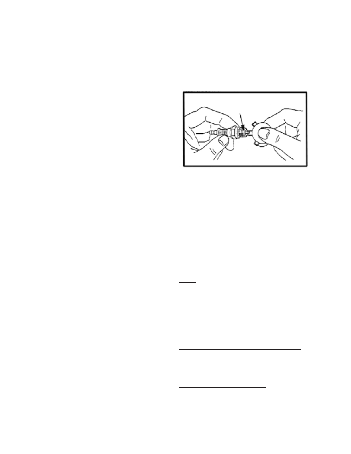
0.028” ~ 0.031”
Install the Air Filter Element or the 4.
cleaned Filter. Secure the Air Cleaner Cover before use.
If damaged, replace the element.5.
Spark Plug Maintenance:
Disconnect Spark Plug Wire from 1.
end of plug. Clean out debris from
around Spark Plug.
Using the spark plug wrench provid-2.
ed, remove the Spark Plug.
Inspect the Spark Plug: 3.
If the electrode is oily, clean it using a clean, dry rag. If the electrode
has deposits on it, polish it using
emery paper. If the white insulator is
cracked or chipped, the Spark Plug
needs to be replaced.
When installing a new Spark Plug 4.
or servicing the existing spark plug,
adjust the Plug’s gap to the specication on the Technical specication
chart and in the illustration below. Do
not pry against the electrode or the
insulator, the Spark Plug can be damaged. (See Figure J.)
Install the new Spark Plug or the 5.
cleaned Spark Plug into the Engine.
FIGURE J
Cleaning, Maintenance, and
Lubrication Schedule: Engine
Note: This maintenance schedule is in-
tended solely as a general guide. If
performance decreases or if the Engine operates unusually, check systems immediately. The maintenance
this Engine needs will differ depending on factors such as temperature,
air quality, fuel quality, and other factors.
Note: These procedures are in addition to
the regular checks and maintenance
explained as part of the regular operation of the Engine.
After Initial 25 Operation Hours:
Change engine oil.a.
Every 25 Operation Hours Thereafter:
Clean/replace Air Filter Element.a.
Inspect/clean Spark Plug.b.
Every 50 Operation Hours:
Change engine oil.a.
SKU 66523 For technical questions, please call 1-800-444-3353. Page 14
Page 15

Every 100 Operation Hours:
Replace Spark Plug.a.
Maintenance and Cleaning
Schedule: Generator
Replace Air Filter Element.b.
Note: All maintenance procedures sched-
uled for 25, 50, and 100 operation
hours should be performed at least
yearly.
Every 300 Operation Hours:
Clean Fuel Tank and Carburetor as-a.
sembly.
Clean carbon build-up from Com-b.
bustion Chamber.
Storage
Wait for Engine to cool, then wipe 1.
Engine with clean cloth.
When the equipment is to remain idle 2.
for longer than 20 days, prepare the
Engine for storage as follows:
Before Every Use:
Check to make sure all bolts and a.
nuts are tight.
Check for any damage to the Gen-b.
erator. If damaged, do not use
until repaired by a qualied service
technician.
After Every Use:
Allow the unit to completely cool. a.
Then clean the exterior of the Generator with a clean cloth.
Change engine oil and empty Fuel a.
Tank.
Clean out area around Spark Plug. b.
Remove Spark Plug and pour one
tablespoon of engine oil into Cylinder through Spark Plug hole.
Reinstall Spark Plug, but leave the c.
Spark Plug Wire disconnected.
Pull Starter Handle to distribute oil d.
in Cylinder. Stop after one or two
revolutions when you feel the Piston
start the compression stroke (when
you start to feel resistance).
Apply a thin coat of rust preventive oil 3.
to all uncoated metal parts.
Cover and store in a dry, well-ventilat-4.
ed area out of reach of children.
SKU 66523 For technical questions, please call 1-800-444-3353. Page 15
Page 16
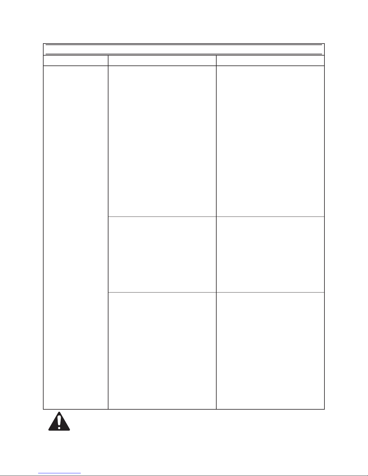
TROUBLESHOOTING - ENGINE
Problem Possible Causes Probable Solutions
Engine will not
start
FUEL RELATED:
No fuel in tank or fuel valve closed.1.
Choke not in start position, 2.
especially with cold engine.
Low quality or deteriorated, old 3.
gasoline.
Carburetor not primed. 4.
Dirty fuel passageways blocking 5.
fuel ow.
Carburetor needle stuck. Fuel can 6.
be smelled in the air.
Too much fuel in chamber. This can 7.
be caused by the carburetor needle
sticking.
IGNITION (SPARK) RELATED:
Spark plug wire not connected 1.
securely.
Spark plug electrode wet or dirty.2.
Incorrect spark plug gap.3.
Spark plug wire or spark plug 4.
broken.
Incorrect spark timing or faulty 5.
ignition system.
COMPRESSION RELATED:
Cylinder not lubricated. Problem 1.
after long storage periods.
Loose or broken spark plug. 2.
(Hissing noise will occur when
trying to start.)
Loose cylinder head or damaged 3.
head gasket. (Hissing noise will
occur when trying to start.)
Engine valves or tappets 4.
misadjusted or stuck.
FUEL RELATED:
Fill fuel tank and open fuel valve.1.
Move choke to start position if 2.
engine is cold.
Use only fresh 91+ octane 3.
unleaded gasoline.
Prime carburetor by pressing 4.
priming bulb specied number of
times (if equipped).
Clean out passageways using 5.
fuel additive. Heavy deposits may
require further cleaning.
Gently tap side of carburetor oat 6.
chamber with screwdriver handle.
Turn choke to run position. 7.
Remove spark plug and pull the
start handle several times to air out
the chamber. Reinstall spark plug
and set choke to start position.
IGNITION (SPARK) RELATED:
Connect spark plug wire properly. 1.
Clean spark plug.2.
Correct spark plug gap.3.
Replace spark plug wire and/or 4.
spark plug.
Have qualied technician diagnose/5.
repair ignition system.
COMPRESSION RELATED:
Pour tablespoon of oil into spark 1.
plug hole. Crank engine a few
times and try to start again. See
Step 7 above.
Tighten spark plug. If that does 2.
not work, replace spark plug. If
problem persists, may have head
gasket problem, see #3 below.
Tighten head. If that does not 3.
remedy problem, replace head
gasket.
Adjust valve clearance. If that does 4.
not work, clean or replace valves/
tappets.
Follow all safety precautions whenever diagnosing or servicing the
equipment or engine.
SKU 66523 For technical questions, please call 1-800-444-3353. Page 16
Page 17
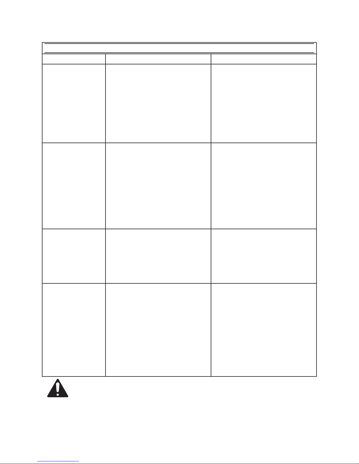
TROUBLESHOOTING - ENGINE
Problem Possible Causes Probable Solutions
Engine misres
Engine stops
suddenly
Engine knocks
Engine backres
Spark plug wire loose.1.
Incorrect spark plug gap or 2.
damaged spark plug.
Defective spark plug wire.3.
Old or low quality gasoline. 4.
Incorrect compression.5.
Low oil shutdown. 1.
Fuel tank empty or full of impure or 2.
low quality gasoline.
Defective fuel tank cap creating 3.
vacuum, preventing proper fuel
ow.
Improper idle speed.4.
Faulty magneto, incorrect timing, or 5.
clogged carburetor.
Old or low quality gasoline. 1.
Engine overloaded. 2.
Incorrect spark timing, deposit 3.
buildup, worn engine, or other
mechanical problems.
Impure or low quality gasoline. 1.
Engine too cold. 2.
Choke not open after engine warm. 3.
Engine not properly adjusted for 4.
high altitude operation.
Intake valve stuck, choke stuck, 5.
incorrect timing, clogged carburetor,
or overheated engine.
Check wire connections.1.
Re-gap or replace spark plug. 2.
Replace spark plug wire.3.
Use only fresh 91+ octane 4.
unleaded gasoline.
Diagnose and repair compression. 5.
(Use Engine will not start:
COMPRESSION RELATED
section.)
Fill engine oil to proper level. 1.
Check engine oil before EVERY
use.
Fill fuel tank with fresh 91+ octane 2.
unleaded gasoline.
Test/replace fuel tank cap. 3.
Properly adjust idle speed.4.
Have qualied technician diagnose 5.
and service engine.
Fill fuel tank with fresh 91+ octane 1.
unleaded gasoline.
Do not exceed equipment’s load 2.
rating.
Have qualied technician diagnose 3.
and service engine.
Fill fuel tank with fresh 91+ octane 1.
unleaded gasoline.
Use cold weather fuel and oil 2.
additives to prevent backring.
Move choke to run position after 3.
engine warms up.
Qualied technician must adjust 4.
engine at altitudes greater than
5,000 feet above sea level.
Have qualied technician diagnose 5.
and service engine.
Follow all safety precautions whenever diagnosing or servicing the
equipment or engine.
SKU 66523 For technical questions, please call 1-800-444-3353. Page 17
Page 18
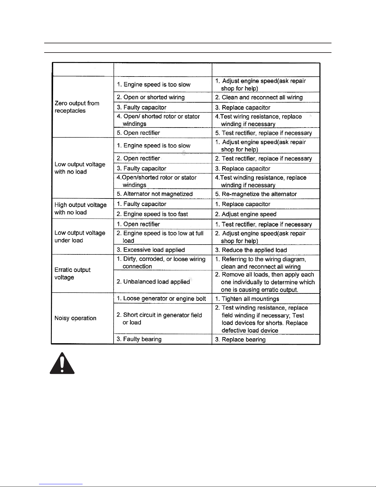
TROUBLESHOOTING - GENERATOR UNIT
Problem Possible Cause Possible Solutions
Follow all safety precautions whenever diagnosing or servicing the
equipment or engine.
SKU 66523 For technical questions, please call 1-800-444-3353. Page 18
Page 19
PARTS LIST - GENERATOR
Part # Description Qty. Part # Description Qty.
1 Bolt (M5 x 10) 2 39 Mufer Cover (Inside) 1
2 Spring Washer (#5) 2 40 Fuel Pipe (Out) 1
3 Washer (#5) 2 41 Fuel Lever 1
4 Cover 1 42 Spring Washer (#6) 1
5 Bolt (M5 x 30) 4 43 Nut (M6) 1
6 Spring Washer (#5) 4 44 Fuel Pipe (In) 1
7 Washer (#5) 4 45 Mufer Exhaust Cover 1
8 Rear Cover (Motor) 1 46 Screw (M6 x12) 3
9 Stator 1 47 Base Plate 1
10 Bolt (M8 x 170) 1 48 Vibration Rubber Pad 4
11 Rotor 1 49 Washer (#6) 4
12 Screw (M6 x 12) 4 50 Bolt (M6 x 16) 4
13 Nut 1 51 Bolt (M8 x 16) 2
14 Fuel Cap 1 52 Washer (#8) 2
15 Spring 1 53 Bolt (M8 x 25) 2
16 Breather 1 54 Petcock Assy. 1
18 Fuel Cap Ring 1 55 Capacitor Mount 1
19 Filter Basket 1 56 Capacitor 1
20 Fuel Tank 1 57 Forward Shroud 1
21 Handle Cover 1 58 Oil Inspection Assy. 1
22 Spark Plug Boot 1 59 Control Panel 1
23 Back Shroud 1 60 AC Circuit Breaker 1
24 Washer (#6) 11 61 AC Outlet 1
25 Screw (M6 x 16) 11 62 Screw (M4 x 16) 2
26 Choke Cover 1 63 Self-Tapping Screw (ST4.2 x 15) 2
27 Mufer Cover (Outside) 1 64 Power Switch 1
28 Self-Tapping Bolt (ST4.2 x 9.5) 8 65 DC Circuit Breaker 1
29 Engine (152F) 1 66 Forward Cover (Motor) 1
30 Mufer 1 67 Spring Washer (#8) 4
31 Cylinder Head Cover (Up) 1 68 Bolt (M8 x 20) 4
32 Cylinder Head Cover (Down) 1 69 Washer (#8) 2
33 Nut (M8) 2 70 Spring Washer (#8) 2
34 Engine Mount 1 71 Nut (M8) 2
35 Washer (#8) 2 72 Washer (#5) 1
36 Bolt (M8 x 16) 2 73 Bolt (M5 x 10) 1
37 Oil Alarm 1
38 Mufer Cover (Outside) 1
SKU 66523 For technical questions, please call 1-800-444-3353. Page 19
Page 20
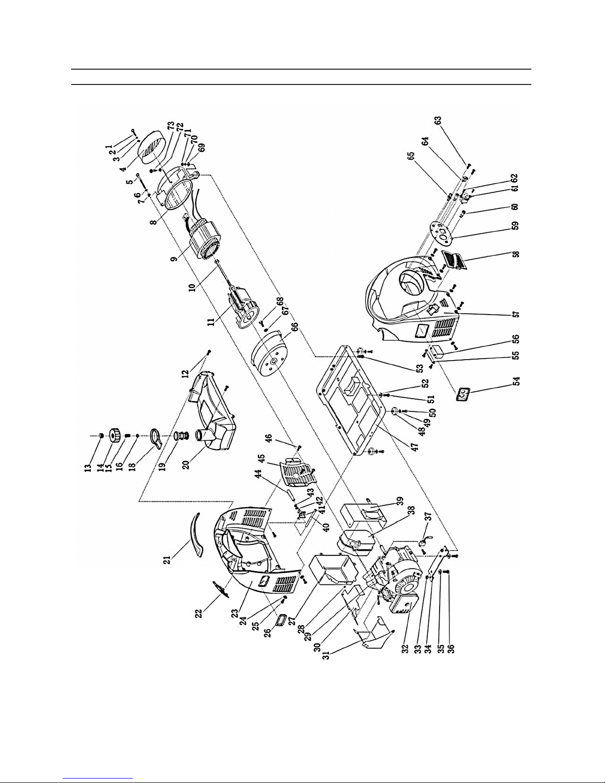
ASSEMBLY DIAGRAM - GENERATOR
SKU 66523 For technical questions, please call 1-800-444-3353. Page 20
Page 21
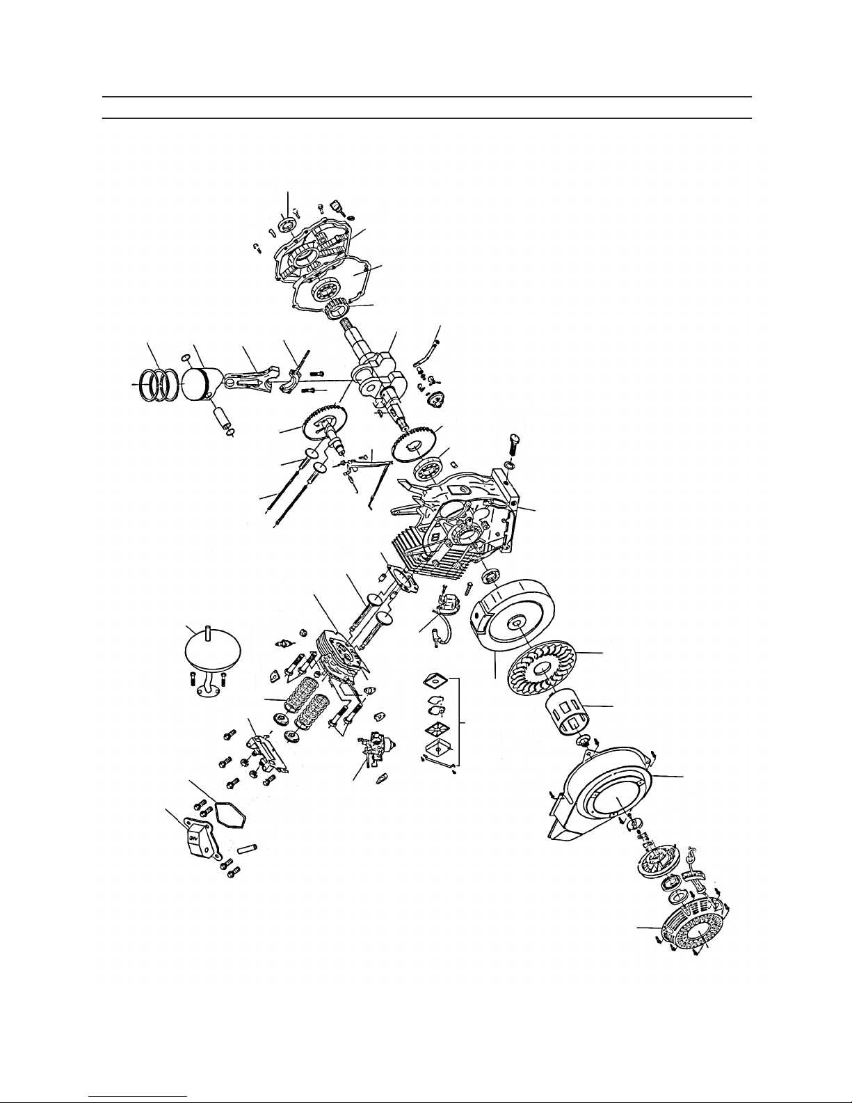
PARTS LIST - ENGINE
No. Description Quantity
1 Crankcase 1
2 Bearing, Crankshaft 1
3 Drive gear 1
4 crankshaft 1
5 Timing drive gear 1
6 Crank case cover gasket 1
7 Crankcase cover 1
8 Oil seal, Crankshaft 1
9 Connecting rod cover 1
10 Shank 1
11 Piston 1
12 Piston ring 3
13 Camshaft assembly 1
14 Tappet 2
15 Pusher 2
16 Regulating frame assembly 1
17 Mufer assembly 1
18 Cylinder head assembly 1
19 Exhaust valve /Intake valve 2
20 Valve spring 2
21 Valve rocker assembly 1
22 Cylinder head cover gasket 1
23 Cylinder head cover assembly 1
24 Carburetor 1
25 Air cleaner assembly 1
26 Ignition coil assembly 1
27 Flywheel 1
28 Flywheel fan 1
29 Starting ange 1
30 Fan hood assembly 1
31 Recoil starter assembly 1
32 Governor assembly 1
33 Cylinder head gasket 1
Note: When ordering parts from this parts list, add an “A” sufx to the number
ordered. Example: Crankcase is part number 1A.
SKU 66523 For technical questions, please call 1-800-444-3353. Page 21
Page 22
12
11
ASSEMBLY DIAGRAM - ENGINE
8
7
Note: When referencing
parts on this diagram. add
an “A” sufx to the number.
10
13
14
6
5
9
4
16
32
3
2
23
17
22
21
15
20
18
19
24
1
33
26
28
27
29
25
30
SKU 66523 For technical questions, please call 1-800-444-3353. Page 22
31
Page 23
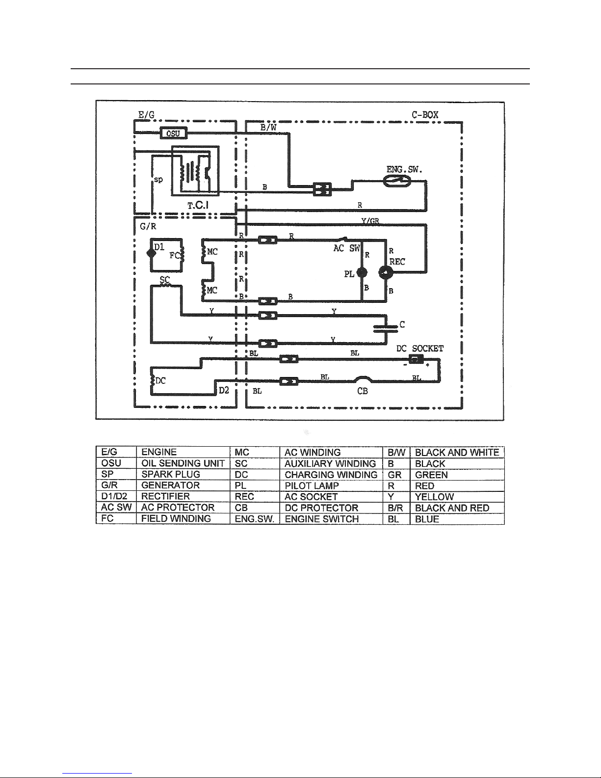
WIRING DIAGRAM
SKU 66523 For technical questions, please call 1-800-444-3353. Page 23
Page 24

LIMITED 1 YEAR / 90 DAY
EMISSION CONTROL
WARRANTY
Harbor Freight Tools Co. makes every effort to
assure that its products meet high quality and durability standards, and warrants to the original purchaser
that for a period of ninety days from date of purchase
that the engine/motor, the belts (if so equipped),
and the blades (if so equipped) are free of defects
in materials and workmanship. Harbor Freight Tools
also warrants to the original purchaser, for a period
of one year from date of purchase, that all other parts
and components of the product are free from defects
in materials and workmanship (90 days if used by
a professional contractor or if used as rental equipment). This warranty does not apply to damage due
directly or indirectly, to misuse, abuse, negligence or
accidents, repairs or alterations outside our facilities, normal wear and tear, or to lack of maintenance.
We shall in no event be liable for death, injuries to
persons or property, or for incidental, contingent,
special or consequential damages arising from the
use of our product. Some states do not allow the
exclusion or limitation of incidental or consequential
damages, so the above limitation of exclusion may
not apply to you. THIS WARRANTY IS EXPRESSLY
IN LIEU OF ALL OTHER WARRANTIES, EXPRESS
OR IMPLIED, INCLUDING THE WARRANTIES OF
MERCHANTABILITY AND FITNESS.
To take advantage of this warranty, the product or part must be returned to us with transportation charges prepaid. Proof of purchase date and an
explanation of the complaint must accompany the
merchandise. If our inspection veries the defect, we
will either repair or replace the product at our election or we may elect to refund the purchase price
if we cannot readily and quickly provide you with a
replacement. We will return repaired products at our
expense, but if we determine there is no defect, or
that the defect resulted from causes not within the
scope of our warranty, then you must bear the cost of
returning the product.
This warranty gives you specic legal rights
and you may also have other rights which vary from
state to state.
3491 Mission Oaks Blvd.
PO Box 6009 • Camarillo, CA 93011
(800) 444-3353
SYSTEM WARRANTY
California and United States Emission Control
Defects Warranty Statement
The California Air Resources Board (herein CARB), the
United States Environmental Protection Agency (herein EPA),
and Harbor Freight Tools (herein HFT) are pleased to explain the
emission control system warranty on your 1995 and later Small
Off-Road Engine (herein engine). In California, the engine must
be designed, built and equipped to meet the State’s stringent
anti-smog standards. Elsewhere within the United States, new
off-road, spark-ignition engines certied for model year 1997 and
later, must meet similar standards set forth by the EPA. HFT
must warrant the emission control system on your engine for
the periods of time described below, provided there has been no
abuse, neglect or improper maintenance of your engine.
Your emission control system may include parts such as the
carburetor or fuel-injection system, and the ignition system. Also
included may be hoses, belts, connectors and other emissionrelated assemblies.
Where a warrantable condition exists, HFT will repair your
engine at no cost to you including diagnosis, parts and labor.
Manufacturer’s Warranty Coverage
The 1995 and later engines are warranted for two
(2) years. If any emission-related part on your engine is
defective, the part will be repaired or replaced by HFT.
Harbor Freight Tools Emission Control Defects
Warranty Coverage
Engines are warranted for a period of two (2) years
relative to emission control parts defects, subject to the
provisions set forth below. If any emission related part
on your engine is defective, the part will be repaired or
replaced by HFT.
Owner’s Warranty Responsibilities
As the engine owner, you are responsible for the •
performance of the required maintenance listed in
your Owner’s Manual. HFT recommends that you
retain all receipts covering maintenance on your
engine, but HFT cannot deny warranty solely for
the lack of receipts or for your failure to ensure the
performance of all scheduled maintenance.
As the engine owner, you should, however, be aware •
that HFT may deny you warranty coverage if your
engine or a part has failed due to abuse, neglect, im-
proper maintenance, or unapproved modications.
You are responsible for shipping your engine to a •
HFT warranty station as soon as a problem exists.
Contact the HFT Customer Service department at
the number below to make shipping arrangements.
The warranty repairs should be completed in a rea-
sonable amount of time, not to exceed 30 days.
If you have any questions regarding your warranty
rights and responsibilities, you should contact the Harbor
SKU 66523 For technical questions, please call 1-800-444-3353. Page 24
Page 25

Freight Tools Customer Service Department at 1-800-444-
3353.
Harbor Freight Tools Emission Control Defects
Warranty Provisions
Length of Coverage1.
HFT warrants to a rst retail purchaser and each subsequent purchaser that the engine is free from defects
in materials and workmanship that cause the failure of
warranted parts for a period of two (2) years after the
date of delivery to the rst retail purchaser.
No Charge Repair or Replacement1.
Repair or replacement of any warranted part will be
performed at no charge to the owner if the work is performed through a warranty station authorized by HFT. For
emissions warranty service, contact the HFT Customer
Service Department at 1-800-444-3353.
Consequential Damages Coverage1.
Coverage under this warranty shall also extend to the
failure of any engine components caused by the failure
of any warranted part while it is still covered under this
warranty.
Coverage Exclusions1.
Warranty claims shall be led in accordance with the
provisions of the HFT warranty policy explained in the
box at the top of the previous page. HFT shall not be
liable for any loss of use of the engine, for any alternative
usage, for any damage to goods, loss of time, or inconvenience. Warranty coverage shall also be excluded
for any part which fails, malfunctions, or is damaged
due to failure to follow the maintenance and operating
instructions set forth in the Owner’s Manual including,
but not limited to:
Use of parts which are not authorized by HFTa.
Improper installation, adjustment or repair of the b.
engine or of any warranted part unless performed
by an authorized warranty center
Failure to follow recommendations on fuel use con-c.
tained in the Owner’s Manual
Improper or inadequate maintenance of any war-d.
ranted parts
Repairs performed outside of the authorized war-e.
ranty service dealers
Alterations by changing, adding to or removing parts f.
from the engine.
Service and Maintenance1.
Component parts which are not scheduled for replacement as required maintenance or are scheduled only
for regular inspection to the effect of “repair or replace
as necessary” are warranted for the warranty period.
Any warranted part which is scheduled for replacement
as required maintenance is warranted for the period of
time up to the rst scheduled replacement point for that
part. Any replacement part, provided it is equivalent in
durability and performance, may be used in performance
of maintenance or repairs. The owner is responsible
for commissioning a qualied technician/mechanic
to perform all required maintenance, as outlined in
the Inspection, Cleaning, and Maintenance section
in this manual.
Warranted Parts1.
Fuel Metering System1.
Carburetor and its internal parts.i.
Fuel pump (if so equipped).ii.
Cold start enrichment system.iii.
Air Induction System1.
Intake pipe/manifold.i.
Air cleaner.ii.
Ignition System1.
Spark plug.i.
Magneto ignition system.ii.
Catalyst System (if so equipped)1.
Exhaust pipe stud.i.
Mufer.ii.
Catalytic converter (if so equipped).iii.
Miscellaneous Items Used in Above Systems1.
Vacuum, temperature and time sensitive i.
valves and switches.
Hoses, belts, connectors, and assem-ii.
blies.
PLEASE READ THE
FOLLOWING CAREFULLY
THE MANUFACTURER AND/OR DISTRIBUTOR HAS
PROVIDED THE PARTS LIST AND ASSEMBLY DIAGRAM IN
THIS MANUAL AS A REFERENCE TOOL ONLY. NEITHER
THE MANUFACTURER OR DISTRIBUTOR MAKES ANY
REPRESENTATION OR WARRANTY OF ANY KIND TO
THE BUYER THAT HE OR SHE IS QUALIFIED TO MAKE
ANY REPAIRS TO THE PRODUCT, OR THAT HE OR
SHE IS QUALIFIED TO REPLACE ANY PARTS OF THE
PRODUCT. IN FACT, THE MANUFACTURER AND/OR
DISTRIBUTOR EXPRESSLY STATES THAT ALL REPAIRS
AND PARTS REPLACEMENTS SHOULD BE UNDERTAKEN
BY CERTIFIED AND LICENSED TECHNICIANS, AND
NOT BY THE BUYER. THE BUYER ASSUMES ALL RISK
AND LIABILITY ARISING OUT OF HIS OR HER REPAIRS
TO THE ORIGINAL PRODUCT OR REPLACEMENT
PARTS THERETO, OR ARISING OUT OF HIS OR HER
INSTALLATION OF REPLACEMENT PARTS THERETO.
Record Product’s Serial Number Here:
________________________________
Note: If product has no serial number, record month and
year of purchase instead.
Note: Some parts are listed and shown for illustration
purposes only, and are not available individually as
replacement parts.
SKU 66523 For technical questions, please call 1-800-444-3353. Page 25
 Loading...