

Page 1

Page 1196
Page 2

- Meets GM contamination sensitivity requirements
Page 3

- Self calibrating
- Micro-processor controlled
- Audio alarm alerts technician
Other Refrigerant Identifiers are being advertised which may be available this A/C season.
However, ONLY the Kent-Moore J 39851 R12 "Pureguard" meets General Motors' current
specifications which ensure recovered refrigerant is compatible with General Motors vehicles and
General Motors approved recovery systems.
An R134a Pureguard Refrigerant Identifier is currently under development and is anticipated to be
available in early 1995. The contamination of R134a refrigerant is not expected to be a concern
until the program to retrofit R12 vehicles to R134a becomes more widely used.
Future bulletins will be issued to address the recovery and disposal of contaminated refrigerant.
Page 4

Steering - Column Popping Noise
Page 5

Steering Column Bearing: All Technical Service Bulletins Steering - Column Popping Noise
Page 6

Group Ref.: Steering/Suspension
Bulletin No.: 333210A
Date: December, 1993
SUBJECT: STEERING COLUMN POPPING NOISE (REPLACE UPPER BEARING INNER RACE
SEAT)
MODELS: 1992-93 PASSENGER CARS EXCEPT CHEVROLET CAVALIER, GEO AND PONTIAC
LEMANS 1992-93 LIGHT DUTY TRUCKS EXCEPT GEO TRACKER
This bulletin is being re-published to add the labor time for Labor Operation Number E7310.
Vehicles affected have TILT steering columns (round style) with the exception of the "W" series
(square style).
CONDITION:
Some owners of vehicles with integral TILT steering columns may hear a pop noise when turning.
The noise occurs specifically when the driver is making normal steering turns in either direction and
generally when the steering wheel is returning to center.
CAUSE:
The upper bearing inner race seat under certain conditions may cause a pop noise. The part may
have a burr on the inside skirt.
CORRECTION:
To verify that the upper bearing inner race seat is the cause of the pop noise in the steering
column, use the following method:
1. Engage the park brake and start the engine.
2. Point the wheels of the vehicle straight ahead.
3. While listening for a pop noise, rotate the steering wheel in either direction to the wheel stop.
Slowly return the wheel back to center. If the noise is not heard, drive the vehicle at a slow speed
listening for the noise to occur.
Important:
When the steering column is warm, the pop noise will be more audible.
4. If a pop noise is heard, replace the upper bearing inner race seat with P/N 7815184. Return the
steering wheel back to center with the wheels of the vehicle pointed straight ahead. Turn the
ignition lock cylinder to "LOCK" position and then begin the repair. Refer to Section 3F5A/3F5B in
the Service Manual to replace the upper bearing inner race seat.
Parts are currently available from GMSPO.
Labor Operation Number: E7310
Labor Time: 0.6 hrs.
For GMC Truck ONLY, use: T7681
Labor Time: 0.4 hrs. (With SIR add .2 hrs.)
Page 7

Page 6305
Page 8

5. Control assembly (49).
Page 9

INSTALL OR CONNECT
1. Cables (53) to the control assembly (49).
2. Vacuum connections to the control assembly (49).
3. Electrical connections to the control assembly (49).
4. Control assembly (49).
5. Screws (50).
Page 10

Page 4112
Page 11
Page 12
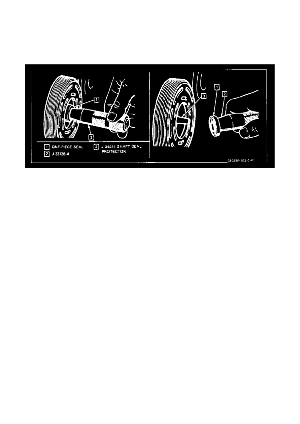
Removing Or Installing Shaft Seal
Page 6257
6. Fully engage the knurled tangs of Seal Remover/Installer J 23128-A into the recessed portion of
the Seal by turning the handle clockwise. Remove
the Seal from the compressor with a rotary-pulling motion. Discard the seal. The handle must be
hand- tightened securely. Do not use a wrench or pliers.
Page 13

Page 5186
Page 14
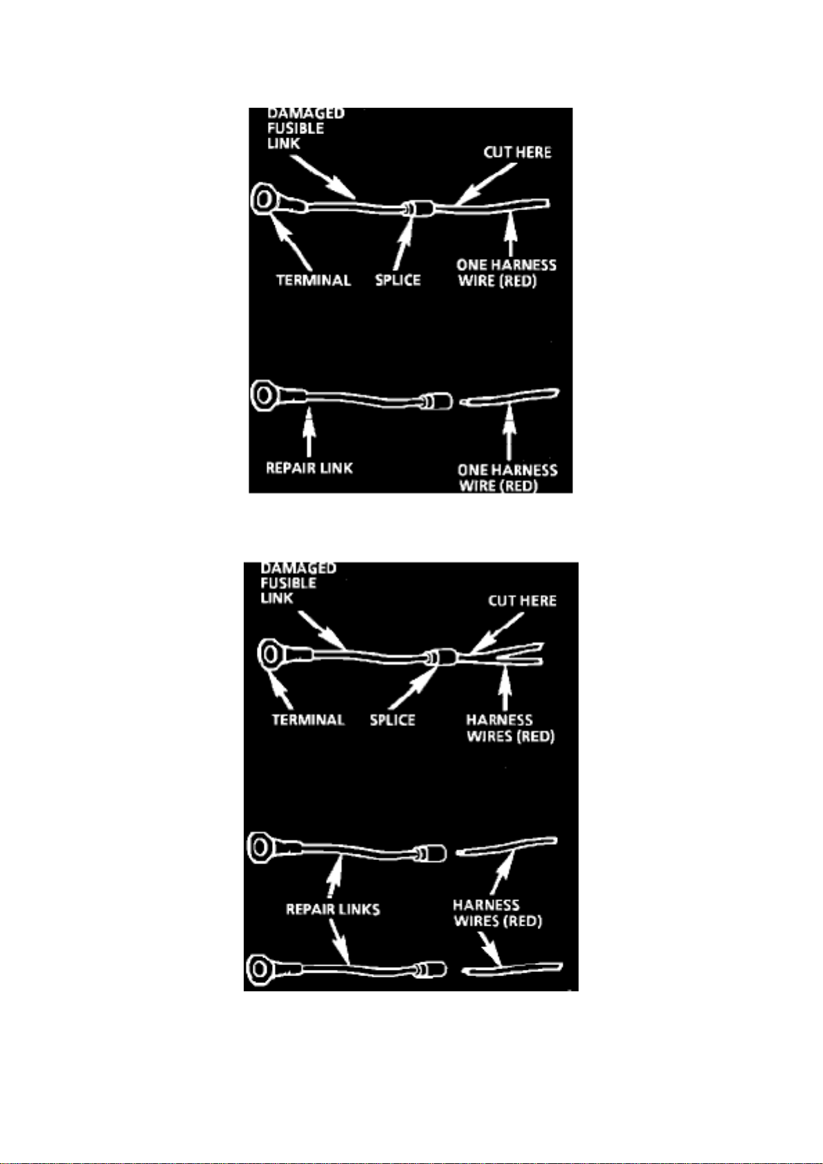
CAUTION: Fusible links cut longer than 225 mm (approx 9 in.) will not provide sufficient overload
protection.
Page 15

Fig. 4 Single Wire Feed Fusible Link
Fig. 5 Double Wire Feed Fusible Link
To replace a damaged fusible link, Fig. 4, cut it off beyond the splice. Replace with a repair link.
When connecting the repair link, strip wire and use staking-type pliers to crimp the splice securely
in two places. For more details on splicing procedures, see Diagnostic Aids/Connector and Wire
Repair. Use Crimp and Seal splices whenever possible.
To replace a damaged fusible link which feeds two harness wires, cut them both off beyond the
splice. Use two repair links, one spliced to each harness wire, Fig. 5.
Typical Electrical Repair
TYPICAL ELECTRICAL REPAIR
An open circuit is an incomplete circuit. Power cannot reach the load or reach ground. If a circuit is
open, active components do not energize. A short circuit is an unwanted connection between one
part of the circuit and either ground or another part of the circuit. A short circuit causes a fuse to
blow or a circuit breaker to open.
SHORT CIRCUITS CAUSED BY DAMAGED WIRE INSULATION
^ Locate the damaged wire.
^ Find and correct the cause of the wire insulation damage.
^ For minor damage, tape over the wire. If damage is more extensive, replace the faulty segment of
the wire.
Splicing Copper Wire Using Splice Clips
The Splice Clip (included in the GM J 38125-A Terminal Repair Kit) is a general purpose wire
repair device. It may not be acceptable for applications having special requirements such as
moisture sealing.
Page 16
Page 7560
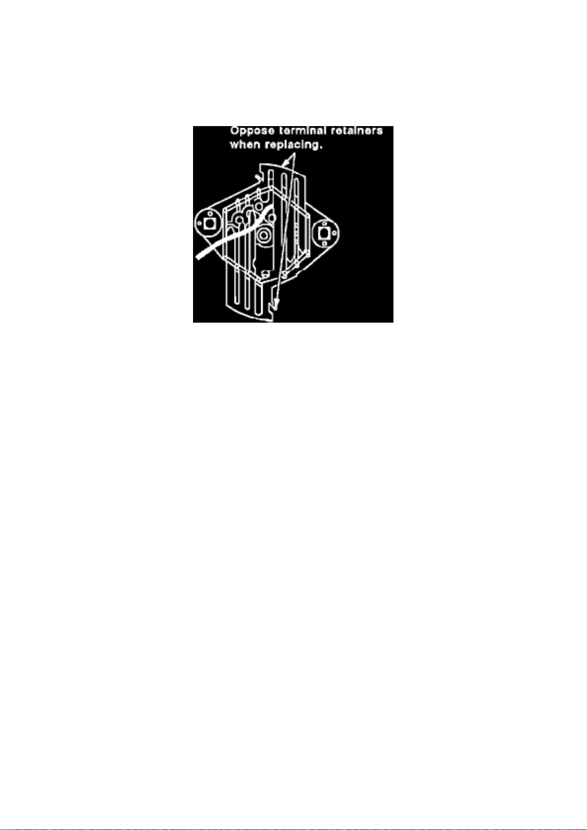
Figure 19
6. Install TPA's, CPA's and/or secondary locks, if equipped (see Figures 18 & 19).
Basic Troubleshooting Guide
TROUBLESHOOTING GUIDELINES
Without a basic knowledge of electricity, it will be difficult to use the diagnostic procedures
contained in this section. You should understand the basic theory of electricity and know the
meaning of voltage, current (amps) and resistance (ohms). You should understand what happens
in a circuit with an open or a shorted wire. You should be able to read and understand a wiring
diagram. The following four-step troubleshooting procedure is recommended:
Step 1: Check the problem Perform a System Check to determine a symptom. Don't waste time
fixing part of the problem! Do not begin disassembly or testing until you have narrowed down the
possible causes.
Step 2: Read the electrical schematic Study the schematic. Read the Circuit Description text if you
do not understand how the circuit should work. Check circuits that share wiring with the problem
circuit. (Shared circuits are shown on Power Distribution, Ground Distribution, Fuse Block Details
and Light Switch Details pages.) Try to operate the shared circuits. If the shared circuits work, then
the shared wiring is OK. The cause must be within the wiring used only by the problem circuit. If
several circuits fail at the same time, chances are the power (fuse) or ground circuit is faulty.
Step 3: Find the fault and repair ^
Narrow down the possible causes.
^ Use the Troubleshooting Hints.
^ Make the necessary measurements or checks as given in the System Diagnosis.
^ Before replacing a component, check power, signal and ground wires at the component harness
connector. If the checks and connections are OK, the most probable cause is component failure.
Page 17

Step 4: Test the repair Repeat the System Check to verify the fault has been corrected and that no
other faults were induced during the repair.
EXAMPLE:
A customer brings in a vehicle and says that the HI beams do not work.
Step 1: Perform a system check on the headlight circuit. You may discover that both LO beams
operate. In "HI," you may notice that the HI Beam Indicator comes on, but neither HI beam
operates.
Page 18

Page 977
Page 19

Drive Belt: Technical Service Bulletins Engine - Serpentine Belt Chirp/Squeak or Premature Wear
Page 20

NUMBER: 93-153A-6B
SECTION: 6B
DATE: August 1993
CORPORATE REFERENCE NUMBER: 3661O1R
SUBJECT: SERPENTINE BELT CHIRP/SQUEAKING OR PREMATURE WEAR
(DIAGNOSE/REPLACE BELT)
MODELS: 1992-93 G VANS 1990-93 M/L VANS AND S/T, C/K TRUCKS
THIS BULLETIN CANCELS AND SUPERSEDES DEALER SERVICE BULLETIN NO. 93-153A-6B,
DATED MARCH 1993. THE 1990-93 C/K TRUCKS HAVE BEEN ADDED. ALL COPIES OF
93-153-6B SHOULD BE DISCARDED.
CONDITION:
Some 1992-93 G-Vans with 4.3L (LB4), 5.OL (L03), 5.7L (L05), 1990-93 M/L Vans with 4.3L (LB4,
L35, LU2), and 1990-93 C/K or S/T Trucks with 4.3L (LB4, L35), 5.0L (L03), or 5.7L (L05) engines
may experience a chirping sound. a squeaking noise, or premature wear on the outer skin of the
serpentine belt accessory drive.
CAUSE/CORRECTION:
The cause of the above conditions can be attributed to the following:
"SQUEAKING NOISE"
This condition typically occurs on vehicles equipped with air conditioning. The condition may be
caused by a belt misalignment between the A/C compressor and the belt tensioner pulley. The belt
misalignment causes the belt to rub against the front, rear, or inner edges of the A/C pulley
grooves, creating a "squeaking" sound. For a multiple ribbed belt it is important that the grooves of
the belt match the grooves in the pulleys. A mirror placed close to the pulley and belt may be
helpful when inspecting the belt to pulley groove match. To verify alignment, place a straight edge
or position a cord across 2 pulleys so they touch at all points. Turn each pulley one half revolution
and recheck with the straight edge or cord. If contact is not made at all points check for a warped or
bent shaft or, refer to the service manual (Section 6B-Engine Cooling) for proper inspection and
adjustments.
NOTE:
Squeaking noise and chirping sounds should not be confused while diagnosing the concern.
"Squeaking is more of a sound which is continuous in nature. "Chirping" is of short duration
intermittent, and a high pitched sound.
"CHIRPING SOUND"
The cause of the chirping sound may be the result of contamination or paint in the pulley grooves.
If contamination or paint is noticed, remove the serpentine belt using procedures in section 6B,
(Engine Cooling) of the service manual. Remove all contamination or paint from all pulley grooves.
A wire brush mounted on an electric drill can be used to perform this operation. Caution should be
taken when using the wire brush. After completion of the cleaning operation, inspect all locations.
The surfaces should be smooth and free from burrs and rough edges. Do not over buff, this may
result in an out of round condition on the pulley. If the power steering pulley is suspect of causing
the chirp sound, verify that the power steering pump pulley is aligned and flush to the power
steering pump assembly, reference section 3B1 (Power Steering) and section 6B (Engine Cooling)
of the service manual for proper inspection and adjustments.
Page 21

NOTE:
Belt dressing is NOT to be used on the serpentine belt. This will only aggravate the chirping
condition.
"PREMATURE WEAR"
This condition will occur on vehicles with air conditioning only. The condition can be identified by
scuffing or marring of the outer belt skin or the belt ribs where a possible interference may take
place.
Page 22
Page 8115
Figure 19
6. Install TPA's, CPA's and/or secondary locks, if equipped (see Figures 18 & 19).
Basic Troubleshooting Guide
TROUBLESHOOTING GUIDELINES
Without a basic knowledge of electricity, it will be difficult to use the diagnostic procedures
contained in this section. You should understand the basic theory of electricity and know the
meaning of voltage, current (amps) and resistance (ohms). You should understand what happens
in a circuit with an open or a shorted wire. You should be able to read and understand a wiring
diagram. The following four-step troubleshooting procedure is recommended:
Step 1: Check the problem Perform a System Check to determine a symptom. Don't waste time
fixing part of the problem! Do not begin disassembly or testing until you have narrowed down the
possible causes.
Step 2: Read the electrical schematic Study the schematic. Read the Circuit Description text if you
do not understand how the circuit should work. Check circuits that share wiring with the problem
circuit. (Shared circuits are shown on Power Distribution, Ground Distribution, Fuse Block Details
and Light Switch Details pages.) Try to operate the shared circuits. If the shared circuits work, then
the shared wiring is OK. The cause must be within the wiring used only by the problem circuit. If
several circuits fail at the same time, chances are the power (fuse) or ground circuit is faulty.
Step 3: Find the fault and repair ^
Narrow down the possible causes.
^ Use the Troubleshooting Hints.
^ Make the necessary measurements or checks as given in the System Diagnosis.
^ Before replacing a component, check power, signal and ground wires at the component harness
connector. If the checks and connections are OK, the most probable cause is component failure.
Page 23

Step 4: Test the repair Repeat the System Check to verify the fault has been corrected and that no
other faults were induced during the repair.
EXAMPLE:
A customer brings in a vehicle and says that the HI beams do not work.
Step 1: Perform a system check on the headlight circuit. You may discover that both LO beams
operate. In "HI," you may notice that the HI Beam Indicator comes on, but neither HI beam
operates.
Page 24
Page 3863
Page 25

Page 26
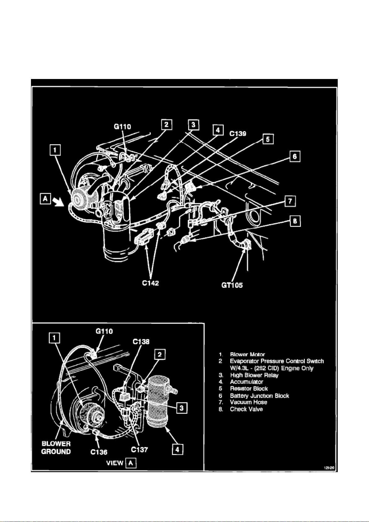
Locations
Page 27

A/C And Heater Wiring
Page 28

Page 825
Page 29
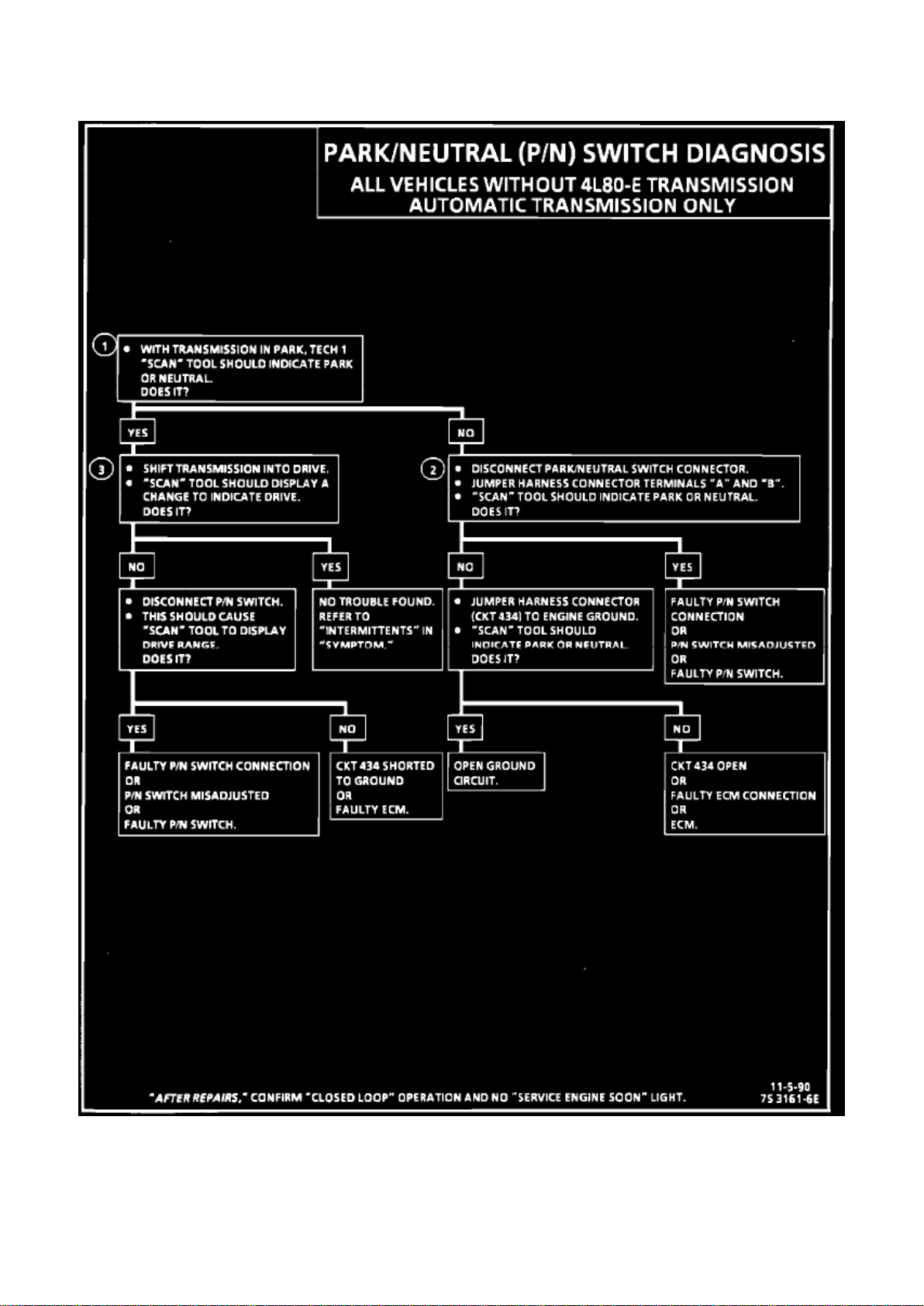
Transmission Position Switch/Sensor: Testing and Inspection
Page 30

Park Neutral Switch Circuit Diagnosis
Page 31

Page 5827
Page 32
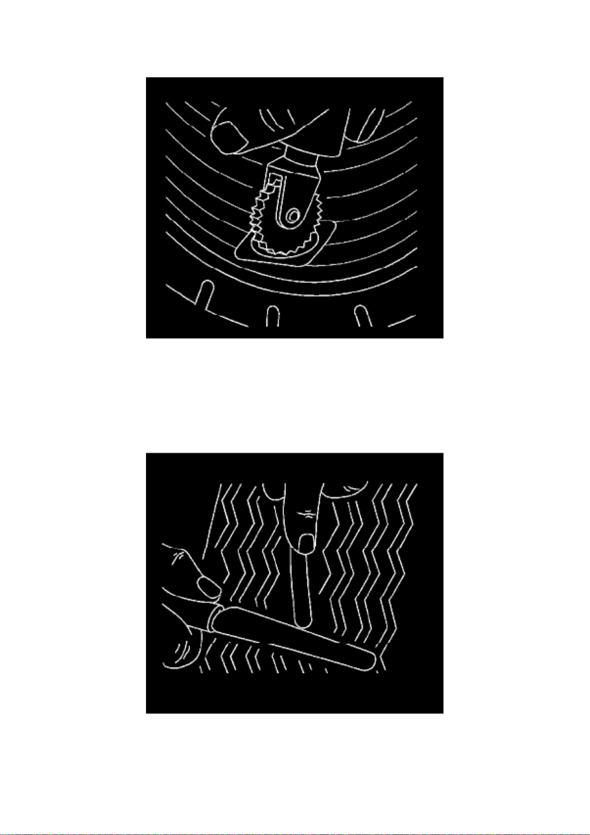
1. The tire must be in the relaxed position when the repair unit is installed (Do not spread the beads
excessively).
Page 33

Two-Piece Plug and Repair Units
1. If applicable, install the repair unit so that the alignment is correct. 2. Center the repair unit over
the injury and stitch down thoroughly with the stitching tool, working from the center out.
3. Being careful not to stretch the plug material, cut the plug flush with the outer tread.
Combination Repair/Plug Units
1. Pull the plug through the injury until the repair just reaches the liner. Stitch down thoroughly. 2.
Follow the repair material manufacturer's recommendations for further installation instructions.
2. Consult your repair material supplier for the proper stitching tool.
Safety Cage
Page 34

Page 7204
Page 35

Orange: ORN
Page 36

Pink: PNK
Purple: PPL
Red: RED
Tan: TAN
White: WHT
Yellow: YEL
Dark: DK (example: DK GRN same as Dark Green)
Light: LT (example: LT BLU same as Light Blue)
Page 37

Tires/Wheels - Low Tire/Leaking Cast Aluminum Wheels
Page 38

Wheels: Customer Interest Tires/Wheels - Low Tire/Leaking Cast Aluminum Wheels
Page 39

TECHNICAL
Bulletin No.: 05-03-10-003F
Date: April 27, 2010
Subject: Low Tire Pressure, Leaking Cast Aluminum Wheels (Repair with Adhesive Sealant)
Models:
2011 and Prior GM Passenger Cars and Light Duty Trucks (Including Saturn) 2010 and Prior
HUMMER H2, H3 2009 and Prior Saab 9-7X with Cast Aluminum Wheels
Supercede: This bulletin is being revised to update the model years and the bulletin reference
information. Please discard Corporate Bulletin Number 05-03-10-003E (Section 03 - Suspension).
Condition
Some customers may comment on a low tire pressure condition.
Diagnosis of the low tire pressure condition indicates an air leak through the cast aluminum wheel.
Cause
Porosity in the cast aluminum wheel may be the cause.
Notice
This bulletin specifically addresses issues related to the wheel casting that may result in an air
leak. For issues related to corrosion of the wheel in service, please refer to Corporate Bulletin
Number 08-03-10-006C - Tire Slowly Goes Flat, Tire Air Loss, Low Tire Pressure Warning Light
Illuminated, Aluminum Wheel Bead Seat Corrosion (Clean and Resurface Wheel Bead Seat).
Correction
1. Remove the tire and wheel assembly from the vehicle. Refer to the appropriate service
procedure in SI. 2. Locate the leaking area by inflating the tire to 276 kPa (40 psi) and dipping the
tire/wheel assembly in a water bath, or use a spray bottle with soap
and water to locate the specific leak location.
Important
- If the porosity leak is located in the bead area of the aluminum rim (where the tire meets the rim),
the wheel should be replaced.
- If two or more leaks are located on one wheel, the wheel should be replaced.
3. If air bubbles are observed, mark the location.
- If the leak location is on the tire/rubber area, refer to Corporate Bulletin Number 04-03-10-001F Tire Puncture Repair Procedures for All Cars and Light Duty Trucks.
- If the leak is located on the aluminum wheel area, continue with the next step.
4. Inscribe a mark on the tire at the valve stem in order to indicate the orientation of the tire to the
wheel. 5. Dismount the tire from the wheel. Refer to Tire Mounting and Dismounting. 6. Remove
the tire pressure sensor. Refer to Tire Pressure Sensor removal procedure in SI. 7. Scuff the
INSIDE rim surface at the leak area with #80 grit paper and clean the area with general purpose
cleaner, such as 3M(R) General Purpose
Page 40

Adhesive Cleaner, P/N 08984, or equivalent.
8. Apply a 3 mm (0.12 in) thick layer of Silicone - Adhesive/Sealant, P/N 12378478 (in Canada, use
88900041), or equivalent, to the leak area. 9. Allow for the adhesive/sealant to dry.
Notice Caution must be used when mounting the tire so as not to damage the sealer. Damaging
the repair area may result in an air leak.
Page 41

A/C - Use of Alternate Refrigerants In CFC 12
Page 42

Refrigerant: Technical Service Bulletins A/C - Use of Alternate Refrigerants In CFC 12
Page 43

Number: 92-250-1A
Section: 0A
Date: AUGUST 1992
Corporate Bulletin No.: 231205
ASE No.: A7
Subject: USE OF ALTERNATE REFRIGERANTS IN CFC 12 REFRIGERANT MOBILE AIR
CONDITIONERS
Model and Year: GALL MODEL YEARS - ALL PASSENGER CARS AND TRUCKS INCLUDING
GEO
A number of inquiries have been received concerning the use of "alternate refrigerants" as a
replacement for R-12 refrigerant in General Motors air conditioning systems.
Regardless of any advertised claims, there are currently no substitutes for refrigerant R-12
approved by General Motors. At the present time, only new or recycled R-12 is approved for use in
General Motors R-12 air conditioning systems.
Based on studies performed to date, the use of "alternate refrigerants" in General Motors R-12 air
conditioning systems may result in higher system pressures, higher leak rates or incompatibility
with drying and sealing materials. System performance and reliability may also be affected.
Service equipment manufacturers have indicated that cross-contaminating R-12 recovery/recycling
equipment with "alternate refrigerants" may damage the equipment. General Motors supports the
Society of Automotive Engineers recommended service procedures for recovery and recycling of
R-12. The use of known "alternate refrigerants" without proper service practices for identifying
vehicle systems containing these "alternate refrigerants" and dedicated recovery equipment to
service those vehicles will contaminate the recycled supply of R-12 refrigerant. Contamination of
the recycled R-12 refrigerant makes the refrigerant unusable for recharging air conditioning
systems and could jeopardize the recycling program.
At the present time, General Motors has not approved any "alternate refrigerant" for R-12 in R-12
air conditioning systems. Therefore, R-12 systems should continue to be serviced with new or
recycled R-12 only.
Page 44
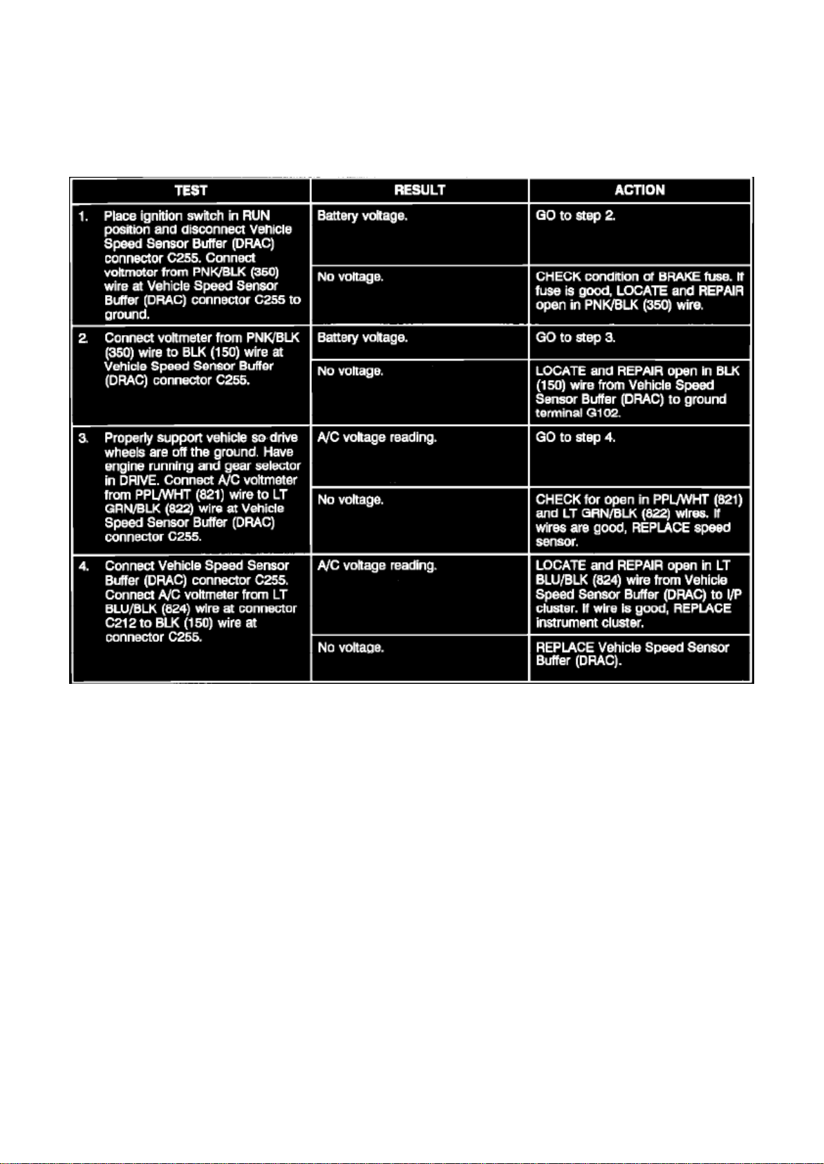
Page 3074
Speed Sensor Components Do Not Operate Properly
Page 45

Interior - Itch Noise From Windshield Pillar Area
Page 46

Instrument Cluster / Carrier: Customer Interest Interior - Itch Noise From Windshield Pillar Area
Page 47

Number: 92-286-10 Section: 10 Date: SEPT. 1992 Corporate Bulletin No.: 261610 ASE No.: B1
Subject: ITCH NOISE FROM WINDSHIELD PILLAR AREA
Model and Year: 1986-92 S/T TRUCKS
Some 1986-1992 S/T utility trucks may exhibit a plastic to metal or plastic to plastic "itch" noise
from the left or right windshield pillar area.
This noise may be caused by the instrument panel pad rubbing against the cowl or dash support
panel.
An adhesive backed felt tape has been released to insulate the dash pad outer corners from the
dash support panel. This tape may also be used on the non-visible surfaces of other trim panels as
necessary to eliminate itch noises.
The felt tape, P/N 12541499, is released in a 10 ft. x 30 mm x 1 mm roll to provide the technician
sufficient material to insulate numerous trim panels.
SERVICE PROCEDURE:
Prior to installing the felt tape, it should be determined if the IP pad to dash support panel is the
area that is generating the noise. Refer to the Squeak and Rattle Diagnosis and Correction Manual
to identify other possible sources such as ECM Mounting Bracket or Air Vent. If it is determined the
IP pad is the source of the noise:
1. Remove the instrument panel radio speaker(s) to obtain better access to the metal ledge on
which the instrument panel pad rests.
2. Remove the 4 IP upper retaining screws located in the defroster duct openings and pull the pad
back slightly.
NOTICE:
Do not remove the dash pad any further than necessary to perform the repair. The possibility exists
that additional noises may be generated due to the wiring and HVAC ducts being mispositioned
upon reinstallation.
3. Cut a strip of felt tape 6 inches long, remove the protective backing and apply the tape to the top
of the metal ledges in front of the speaker openings where the instrument panel pad rests.
NOTICE:
Installation is easier if 2 screwdrivers are wedged between instrument panel pad and the cowl
panel to raise the IP pad.
4. Push the IP pad forward and reinstall the retaining screws and speakers.
Page 48
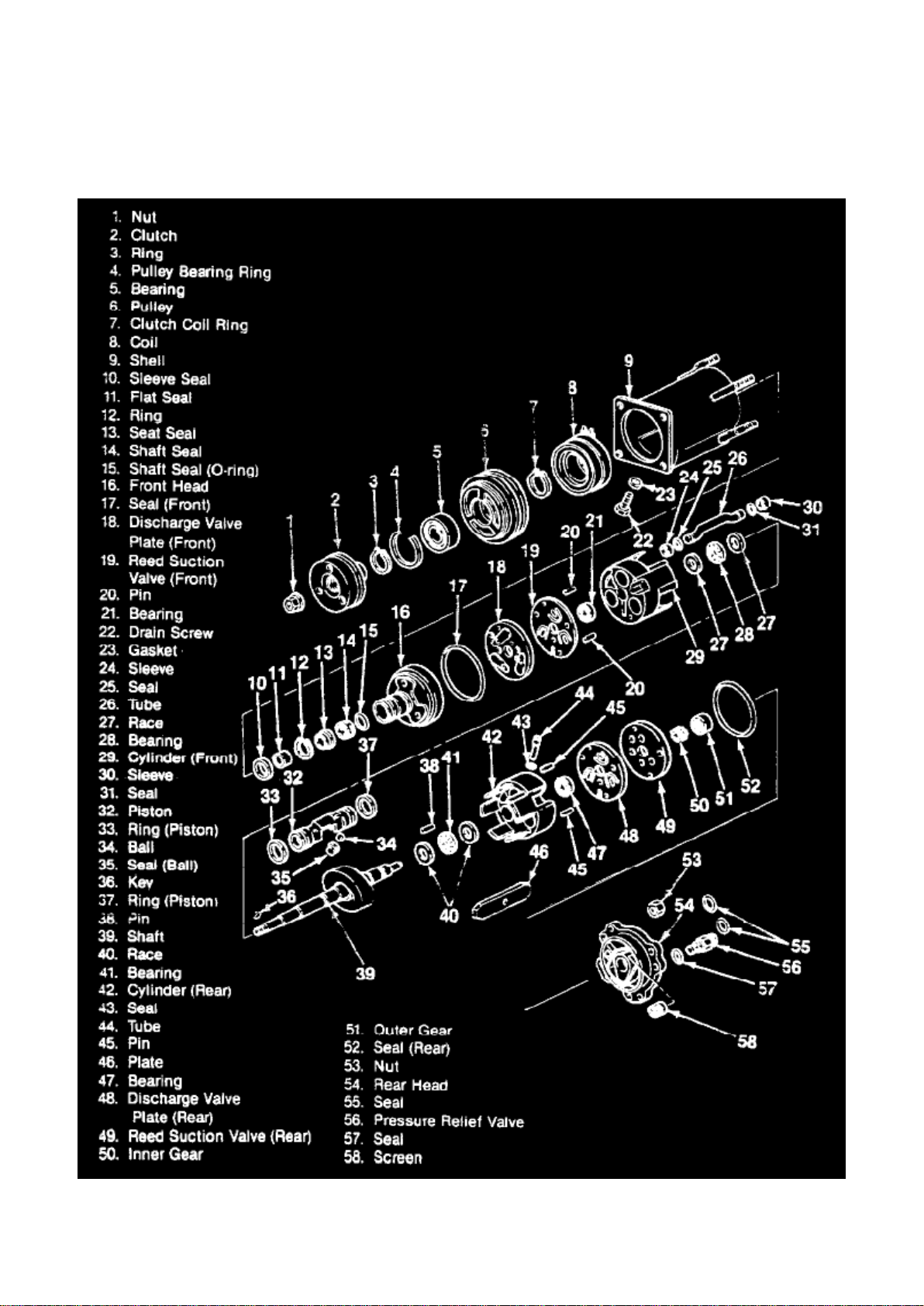
With A-6 Compressor
Page 49

Compressor Clutch Coil: Service and Repair With A-6 Compressor
Remove or Disconnect
Tool Required:
J 6435 External Snap Ring Pliers
1. Clutch plate and hub assembly (2).
2. Pulley (6).
- Mark or scribe the location of the clutch coil (8) to terminal on the compressor front head (16).
Page 50

Page 6461
Page 51

- Install the blower switch knob.
Page 52

2. Control cables (60 and 65).
3. Electrical connection (82).
4. Control assembly (63).
NOTICE: Refer to "Fasteners" under "Vehicle Damage Warnings."
5. Screws (64).
- Check circuit operation.
Page 53

Page 8134
Page 54

Brake Lamp: Description and Operation
Page 55

Voltage is supplied at all times through the STOP-HAZ Fuse to the Brake Switch. When the brake
pedal is depressed, the contacts in the Brake Switch close. Voltage is supplied through the Turn
Switch Assembly tot he LH and RH Stoplamp, and the Stoplamps lights. If a Turn Signal is on, the
Stoplamp on that side will flash as a Turn Signal. The other Stoplamp will serve as a Stoplamp.
Page 56

Page 4554
Page 57
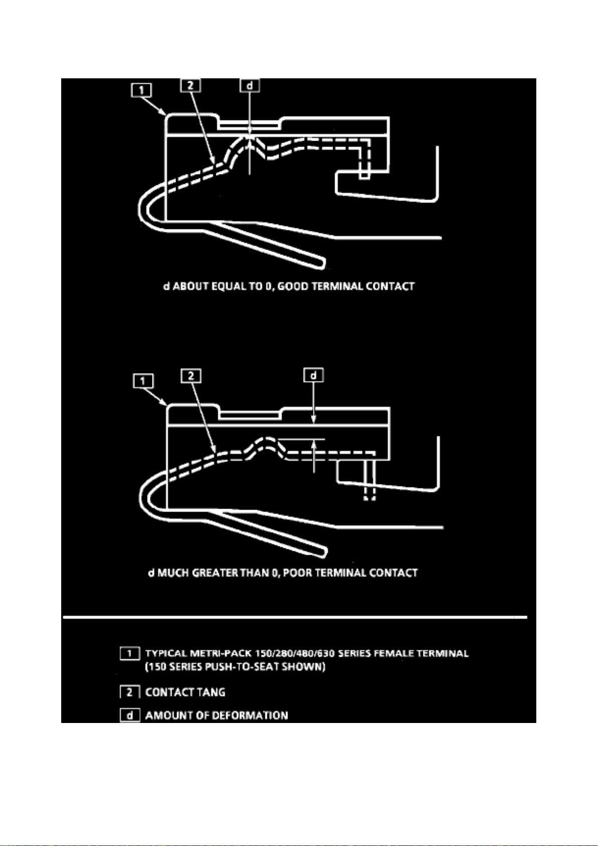
Fig. 7 Deformation of a Typical Metri-Pak Series Female Terminal
Page 58

DESCRIPTION
When diagnosing an electrical system that utilizes Metri-Pack 150/280/480/630 series terminals
(refer to GM Terminal Repair Kit, J 38125-A, instruction manual, J 38125-4 for terminal
identification), it is important to check terminal contact between a connector and component, or
between in-line connectors, before replacing a suspect component.
Frequently, a diagnostic chart leads to a step that reads: "Check for poor connection." Mating
terminals must be inspected to assure good terminal contact. A poor connection between the male
and female terminal at a connector may be the result of contamination or deformation.
Contamination is caused by the connector halves being improperly connected, a missing or
damaged connector seal, or damage to the connector itself, exposing the terminals to moisture and
dirt. Contamination, usually in underhood or underbody connectors, leads to terminal corrosion,
causing an open circuit or intermittently open circuit.
Deformation is caused by probing the mating side of a connector terminal without the proper
adapter, improperly joining the connector halves or repeatedly separating and joining the connector
halves. Deformation, usually to the female terminal contact tang, can result in poor terminal
contact, see Fig. 7, causing an open or intermittently open circuit.
PROCEDURES:
Follow the procedure below to check terminal contact.
1. Separate the connector halves.
2. Inspect the connector halves for contamination. Contamination will result in a white or green
build-up within the connector body or between
terminals, causing high terminal resistance, intermittent contact or an open circuit. An underhood or
underbody connector that shows signs of contamination should be replaced in its entirety:
terminals, seals and connector body.
Page 59

Page 3825
Page 60

Case: Specifications
Page 61

COMPONENT .....................................................................................................................................
...................................................... Torque/Ft.Lbs.
Accumulator Cover To Case ...............................................................................................................
................................................................................. 8 Case Extension To Case ................................
..............................................................................................................................................................
....... 26 Auxiliary Valve Body To Case ................................................................................................
............................................................................................ 8 Bellhousing To Case ...........................
..............................................................................................................................................................
................. 55 Pump Assembly To Case .............................................................................................
...................................................................................................... 18 Solenoid Assembly To Case ...
..............................................................................................................................................................
.............................. 18 Spacer Plate Support To Case ........................................................................
...................................................................................................................... 8 Transmission Oil Pan
To Case ...............................................................................................................................................
.............................................. 8
Page 62

Page 5967
longer.
Important Whenever a wheel is refinished, the mounting surface and the wheel nut contact
surfaces must not be painted or clearcoated. Coating these surfaces could affect the wheel nut
torque.
When re-mounting a tire on an aluminum wheel, coated balance weights must be used in order to
reduce the chance of future cosmetic damage.
Disclaimer
Page 63

Page 185
Page 64
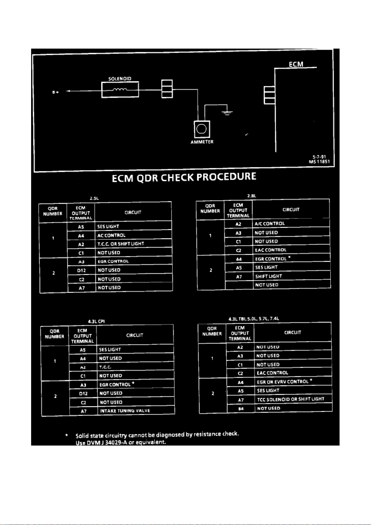
ECM QDR Check Procedure
Page 65

Page 1771
Page 66

Drive Belt: Technical Service Bulletins Engine - Serpentine Belt Chirp/Squeak or Premature Wear
Page 67

NUMBER: 93-153A-6B
SECTION: 6B
DATE: August 1993
CORPORATE REFERENCE NUMBER: 3661O1R
SUBJECT: SERPENTINE BELT CHIRP/SQUEAKING OR PREMATURE WEAR
(DIAGNOSE/REPLACE BELT)
MODELS: 1992-93 G VANS 1990-93 M/L VANS AND S/T, C/K TRUCKS
THIS BULLETIN CANCELS AND SUPERSEDES DEALER SERVICE BULLETIN NO. 93-153A-6B,
DATED MARCH 1993. THE 1990-93 C/K TRUCKS HAVE BEEN ADDED. ALL COPIES OF
93-153-6B SHOULD BE DISCARDED.
CONDITION:
Some 1992-93 G-Vans with 4.3L (LB4), 5.OL (L03), 5.7L (L05), 1990-93 M/L Vans with 4.3L (LB4,
L35, LU2), and 1990-93 C/K or S/T Trucks with 4.3L (LB4, L35), 5.0L (L03), or 5.7L (L05) engines
may experience a chirping sound. a squeaking noise, or premature wear on the outer skin of the
serpentine belt accessory drive.
CAUSE/CORRECTION:
The cause of the above conditions can be attributed to the following:
"SQUEAKING NOISE"
This condition typically occurs on vehicles equipped with air conditioning. The condition may be
caused by a belt misalignment between the A/C compressor and the belt tensioner pulley. The belt
misalignment causes the belt to rub against the front, rear, or inner edges of the A/C pulley
grooves, creating a "squeaking" sound. For a multiple ribbed belt it is important that the grooves of
the belt match the grooves in the pulleys. A mirror placed close to the pulley and belt may be
helpful when inspecting the belt to pulley groove match. To verify alignment, place a straight edge
or position a cord across 2 pulleys so they touch at all points. Turn each pulley one half revolution
and recheck with the straight edge or cord. If contact is not made at all points check for a warped or
bent shaft or, refer to the service manual (Section 6B-Engine Cooling) for proper inspection and
adjustments.
NOTE:
Squeaking noise and chirping sounds should not be confused while diagnosing the concern.
"Squeaking is more of a sound which is continuous in nature. "Chirping" is of short duration
intermittent, and a high pitched sound.
"CHIRPING SOUND"
The cause of the chirping sound may be the result of contamination or paint in the pulley grooves.
If contamination or paint is noticed, remove the serpentine belt using procedures in section 6B,
(Engine Cooling) of the service manual. Remove all contamination or paint from all pulley grooves.
A wire brush mounted on an electric drill can be used to perform this operation. Caution should be
taken when using the wire brush. After completion of the cleaning operation, inspect all locations.
The surfaces should be smooth and free from burrs and rough edges. Do not over buff, this may
result in an out of round condition on the pulley. If the power steering pulley is suspect of causing
the chirp sound, verify that the power steering pump pulley is aligned and flush to the power
steering pump assembly, reference section 3B1 (Power Steering) and section 6B (Engine Cooling)
of the service manual for proper inspection and adjustments.
Page 68

NOTE:
Belt dressing is NOT to be used on the serpentine belt. This will only aggravate the chirping
condition.
"PREMATURE WEAR"
This condition will occur on vehicles with air conditioning only. The condition can be identified by
scuffing or marring of the outer belt skin or the belt ribs where a possible interference may take
place.
Page 69
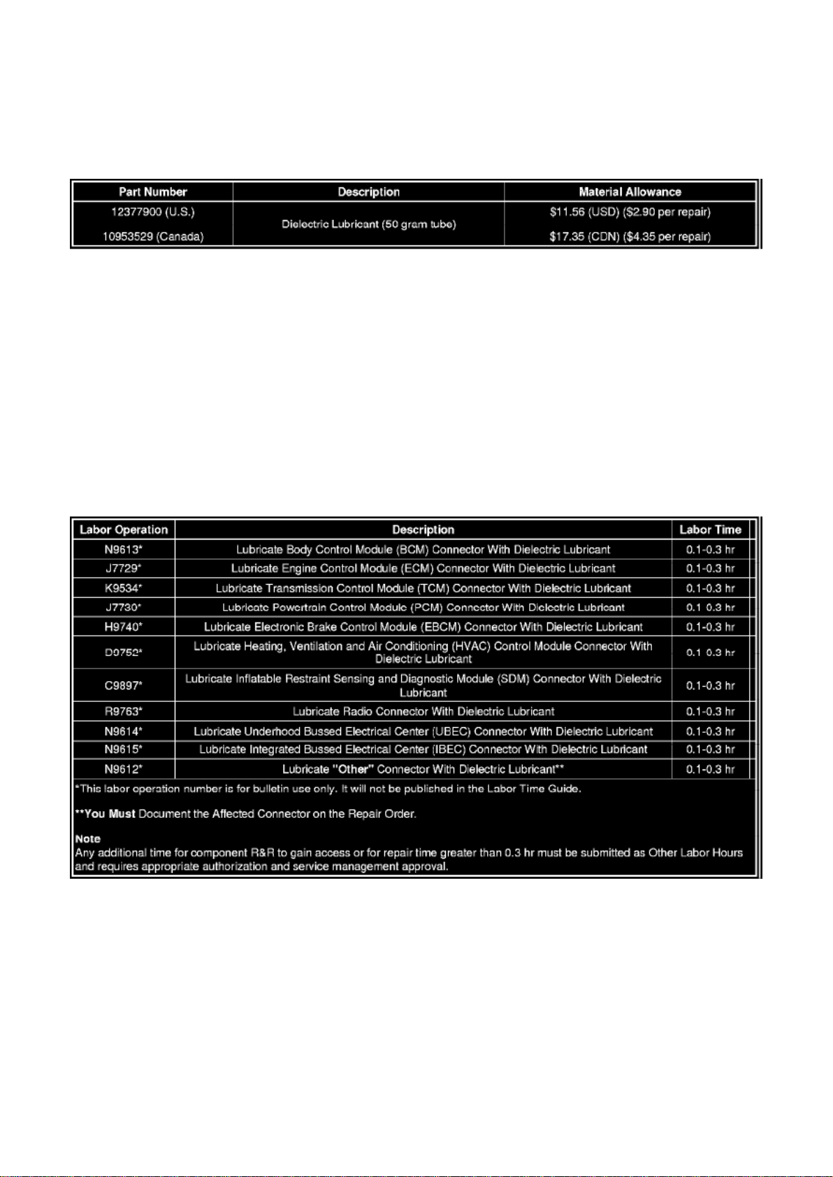
Page 13
Important The following information MUST be documented on the repair order. Failure to do so
may result in a chargeback.
- Customer vehicle condition.
- Was a Service Lamp or Service Message illuminated? If yes, specify which Service Lamp or
Service Message.
- Was a DTC(s) set? If yes, specify which DTC(s) were set.
Page 70

- After following the procedure contained within this bulletin, could the condition be duplicated?
‹› If the condition was not duplicated, then document the affected module/component connector
name and number on the repair order.
- If the condition was duplicated after the procedure contained within this bulletin was followed, and
additional diagnosis led to the replacement of a module or component, the SI Document ID
Number MUST be written on the repair order.
Parts Information
Alternate Distributor For All of North America
Note
NyoGel(R) 760G Lubricant* is equivalent to GMSPO P/N 12377900, and P/N 10953529 (Canada),
specified for use to correct the condition in this bulletin.
*We believe this source and their products to be reliable. There may be additional manufacturers of
such products/materials. General Motors does not endorse, indicate any preference for, or assume
any responsibility for the products or material from this firm or for any such items that may be
available from other sources.
Warranty Information (excluding Saab Models)
For vehicles repaired under warranty, use the appropriate/closest labor operation depending upon
the module/component connection that the dielectric lubricant was applied to:
Warranty Information (Saab Models)
Page 71
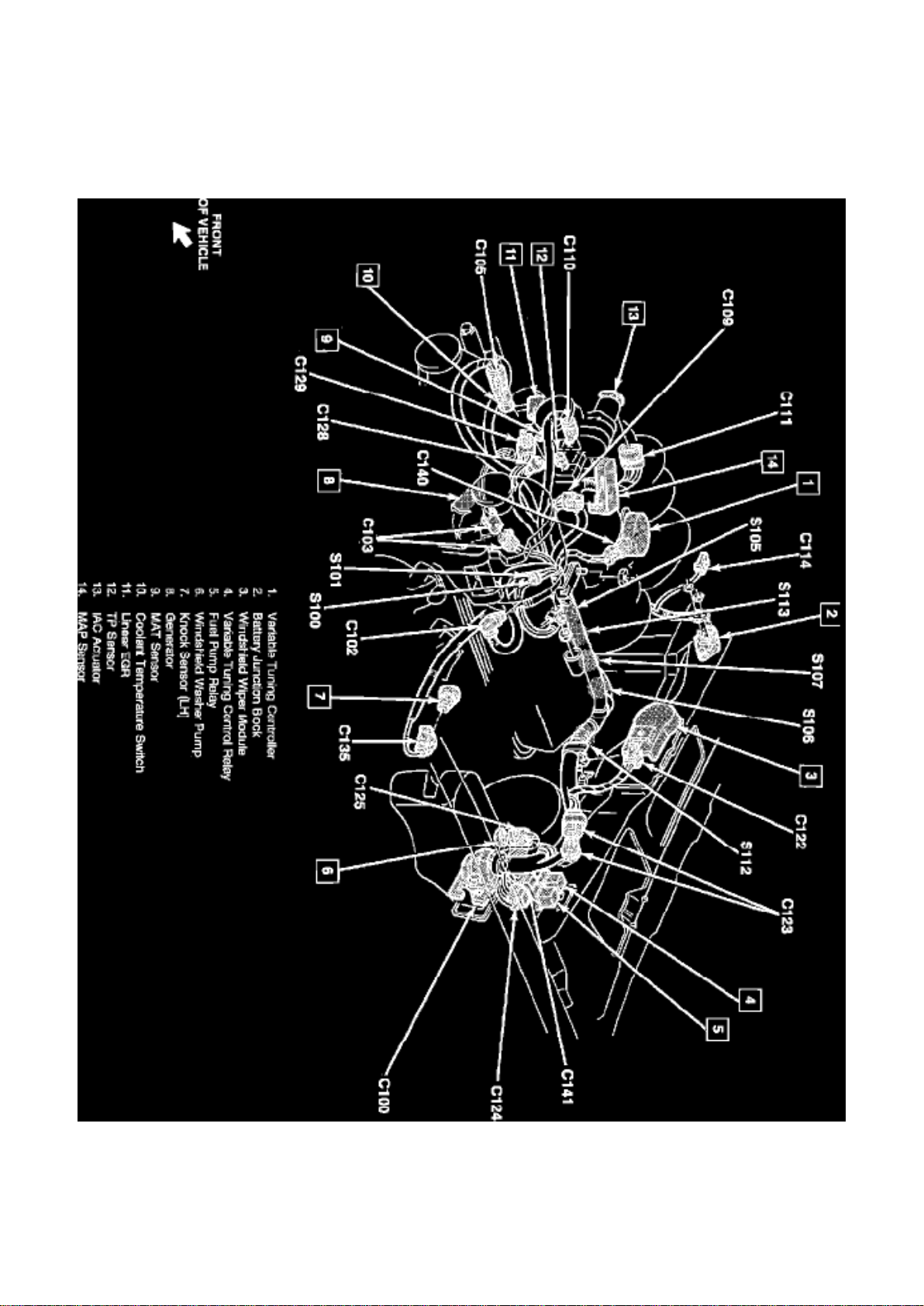
Coolant Temperature Switch
Engine Wiring, LH Side
Page 72

A/T - Intermittent Slip, Downshift, or Busy Cycling TCC
Page 73

Torque Converter Clutch: All Technical Service Bulletins A/T - Intermittent Slip, Downshift, or Busy
Cycling TCC
Page 74

Number: 92-42-7A
Section: 7A
Date: NOV. 1991
Corporate Bulletin No.: 167105
ASE No.: A2
Subject: INTERMITTENT TRANSMISSION DOWNSHIFT, SLIP OR BUSY/CYCLING TCC
Model and Year: 1983-92 ALL PASSENGER CARS AND TRUCKS WITH AUTOMATIC
TRANSMISSION
Some owners may comment that their vehicle is experiencing one or more of the following
transmission conditions:
- Intermittent slipping.
- Intermittent downshift followed by an upshift, both with no apparent reason.
- Busyness or cycling of the TCC at steady throttle conditions and level roadway.
The cooling fan operates when the thermostat on the fan clutch reaches a preset temperature.
When this temperature is reached, the fan engages to draw additional air through the radiator and
lower the engine temperature. When the cooling fan engages, noise increases and may sound very
similar to an increase in engine RPM due to transmission downshift, slipping or TCC cycling. When
engine temperature lowers to a preset point the fan clutch will disengage. When the cooling fan
disengages, noise levels will decrease and may sound very similar to a decrease in engine RPM.
The type of concern described above requires further definition and the customer should be asked
several questions:
- Is the situation more pronounced at higher vehicle loads or pulling a trailer?
- Do warmer ambient temperatures make the situation more pronounced as well?
If the customer's responses indicate that both of these conditions apply, and your observation of
the vehicle confirms a properly operating vehicle, provide the customer the vehicle operating
description included in this bulletin. Further action may not be necessary.
A service procedure follows if further definition is required.
SERVICE PROCEDURE:
When attempting to diagnose an intermittent transmission downshift, slip or busy/cycling TCC:
1. Check fluid level and condition as outlined in section 7A of the appropriate service manual.
2. Test drive the vehicle under the conditions described by the customer (ambient temperature,
engine coolant temperature, trailering, etc.). It may be
necessary to partially restrict airflow to the radiator to raise engine coolant temperature to match
customer conditions.
3. Monitor engine RPM and engine coolant temperature using a scan tool.
4. Listen for an apparent increase in engine RPM.
Page 75

If engine RPM sounds like it increases, check the scan tool RPM and coolant temperature
readings. If the noise increase is due to engagement of the fan the engine RPM will not increase
and engine coolant temperature will begin to decrease after the fan engages. As the fan runs the
engine coolant temperature will drop and the fan will disengage reducing noise levels, engine RPM
will not decrease. This cycle will repeat as engine coolant temperature again rises.
If the above procedure shows the condition to be cooling fan related, no further action is necessary.
The vehicle should be returned to the customer and the condition explained.
If the above procedure shows the condition to be other than cooling fan related, refer to section 7A
of the appropriate service manual for transmission diagnosis information.
Intermittent Transmission Downshift
All light duty trucks are equipped with a thermostatic engine cooling fan. This fan is designed to
provide greater fuel efficiency and quieter operation
Page 76
Page 3114
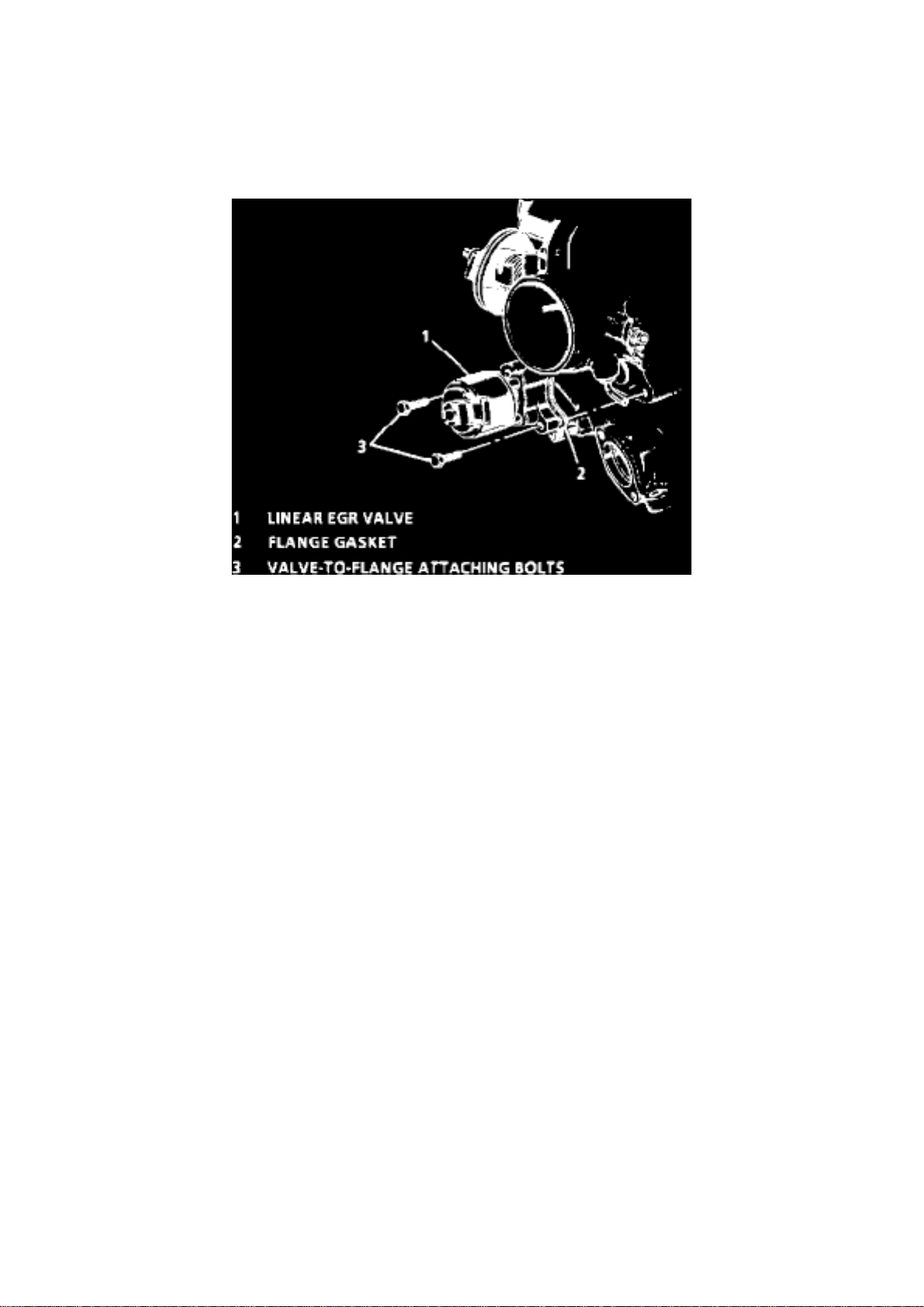
Linear EGR Valve Central MFI
Page 77
Page 5187
Page 78

Step 1: Open the Harness
If the harness is taped, remove the tape. To avoid wire insulation damage, use a sewing "seam
ripper" to cut open the harness (available from sewing supply stores). If the harness has a black
plastic conduit, simply pull out the desired wire.
Step 2: Cut the Wire
Begin by cutting as little wire off the harness as possible. You may need the extra length of the wire
later if you decide to cut more wire off to change the location of a splice. You may have to adjust
splice locations to make certain that each splice is at least 40 mm (1-1/2") away from other splices,
harness branches or connectors.
Step 3: Strip the Insulation
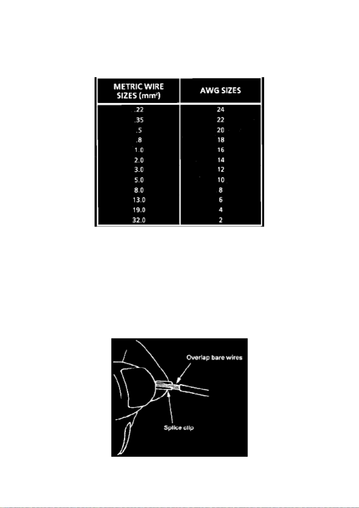
Fig. 6 Wire Size Conversion Table
When replacing a wire, use a wire of the same size as the original wire or larger. The schematics
list wire size in metric units. See table, Fig. 6, for the commercial (AWG) wire sizes that can be
used to replace each metric wire size. Each AWG size is either equal to or larger than the
equivalent metric size. To find the correct wire size either find the wire on the schematic and
convert the metric size to the AWG size, or use an AWG wire gage. If you aren't sure of the wire
size, start with the largest opening in the wire stripper and work down until a clean strip of the
insulation is removed. Be careful to avoid nicking or cutting any of the wires.
Step 4: Crimp the Wires
Page 79

Wheels (Steel) - Damage Due to Improper Mounting
Page 80

Wheels: All Technical Service Bulletins Wheels (Steel) - Damage Due to Improper Mounting
Page 81

Number: 92-232-3E
Section: 3E
Date: JUNE 1992
Corporate Bulletin No.: 233002
ASE No.: A4
Subject: AVOIDING DAMAGE TO STEEL WHEELS FROM IMPROPER WHEEL/TIRE CHANGING
TECHNIQUES
Model and Year: 1983-92 ALL PASSENGER CARS AND TRUCKS WITH STEEL WHEELS
It is important to use proper procedures to prevent damage to either the tire mounting surface or
the wheel mounting holes. Damage can result from the improper wheel attachment or tire mounting
techniques on vehicles with steel wheels.
1. IMPROPER TIRE CHANGING TECHNIQUES:
It takes about 70 seconds for the air to completely exhaust from a large tire. If the technician
doesn't wait this amount of time after removing the valve core, the bead breaker on the tire change
could put enough force on the tire to bend the wheel at the mounting surface. Such damage can
result in vibration, shimmy, and under severe usage (i.e. police vehicle) lead to cracking.
2. OVER TORQUING OF THE WHEEL NUTS:
The service specification for wheel nuts is listed in the Service Manuals. Some wheels have been
observed with wheel nuts that were over torqued by as much as 50 percent. This may damage the
wheel mounting holes and may also lead to cracks.
I. PROPER TIRE CHANGING TECHNIQUES:
Completely deflate the tire before attempting to break the tire bead loose.
MOUNTING SURFACE CHECKING PROCEDURE
Page 82

Page 4412
Page 83

Case: Specifications MUNCIE 5LM60 (HM-290) 4 & 5 Speed
Page 84

Transmission Case Bolts .....................................................................................................................
.................................................................... 27 ft. lbs.
Page 85
Page 650
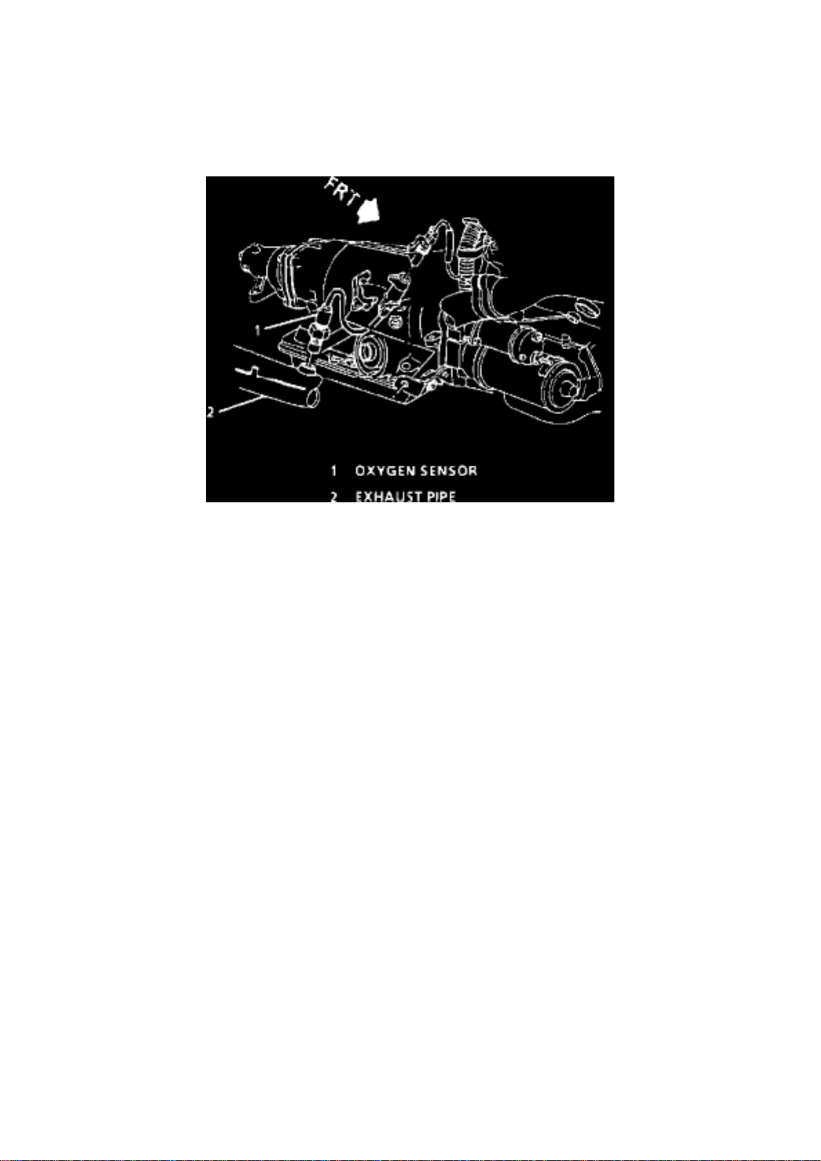
Oxygen Sensor Location
Page 86

Page 7625
Page 87
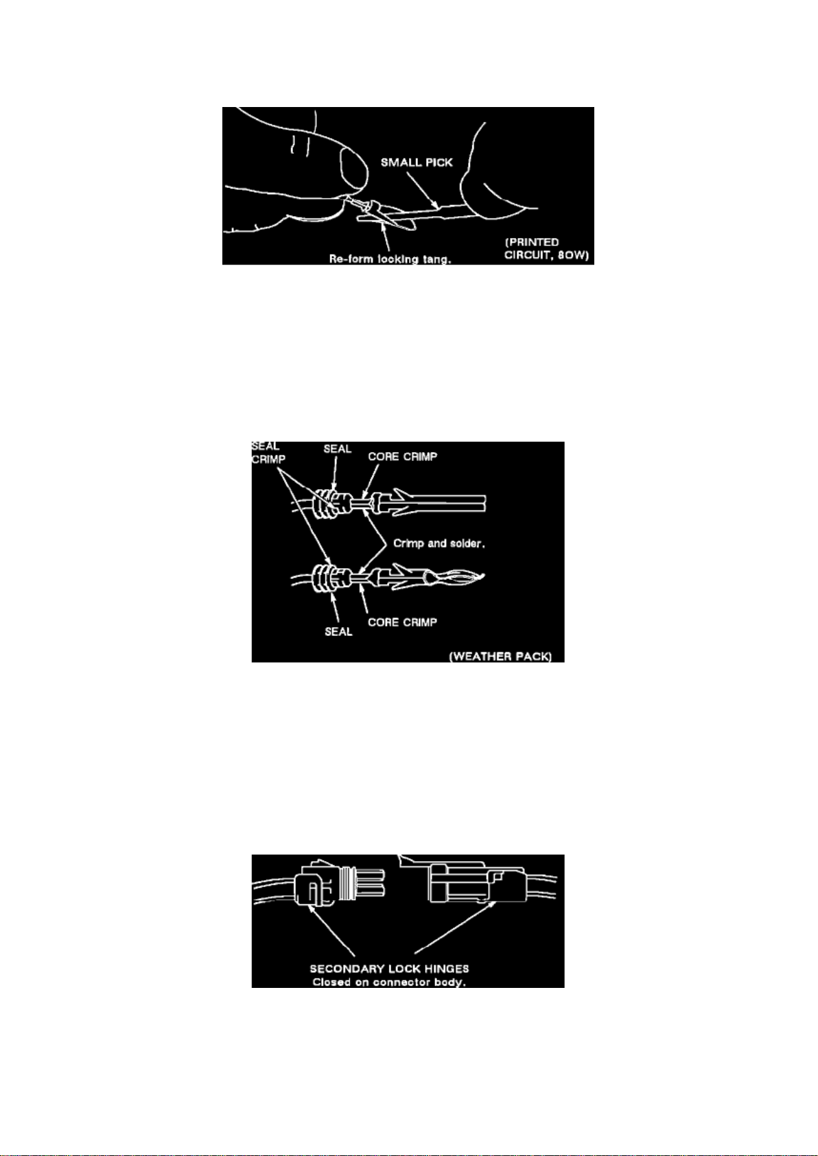
Figure 15
Page 88

Figure 16
3. If terminal is to be re-used, re-form locking tang (see Figures 12 through 16).
4. Make repair. When using a new terminal: a.
Slip cable seal away from terminal (if seal exist).
b. Cut wire as close to terminal as possible.
c. Slip a new cable seal onto wire (if necessary).
d. Strip 3/16" (5 mm) of insulation from wire.
Figure 17
e. Crimp a new terminal to the wire (Figure 17).
f. Solder with rosin core solder.
g. Slide cable seal toward terminal (if equipped with a seal).
h. Crimp cable seal and insulation (if equipped with a seal, see Figure 17).
i. Apply grease to connectors outside the passenger compartment where the connector originally
was equipped with grease.
To re-use a terminal or lead assembly, see previous steps c through i for repairs. Be sure to keep
cable seal (if equipped) on terminal side of splice.
5. Insert lead from the back until it catches.
Figure 18
Page 89

Page 1467
service operation. A simple distraction or time constraint that rushes the job may result in personal
injury if the greatest of care is not exercised. Make it a habit to double check your work and to
always side with caution when installing wheels.
Disclaimer
Page 90
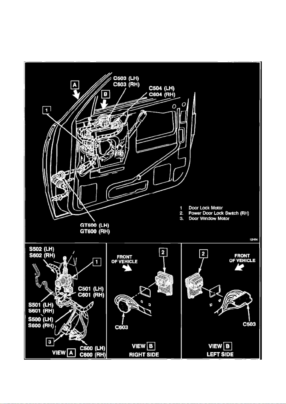
Door Window Motor
Page 91

RH Door Harness (LH Typical)
Page 92

Digital Ratio Adapter/Controller (DRAC) - Service
Page 93

Vehicle Speed Sensor: All Technical Service Bulletins Digital Ratio Adapter/Controller (DRAC) Service
Page 94

Group Ref.: 8 - Chassis/Body Electrical
Bulletin No.: 448301
Date: August, 1994
INFORMATION
SUBJECT: NEW PROCEDURE FOR OBTAINING SERVICE DRACS (DIGITAL RATIO
ADAPTOR/CONTROLLER)
MODELS: 1989-94 CHEVROLET AND GMC TRUCK M/L VANS, S/T MODELS 1990-94
CHEVROLET AND GMC TRUCK G VANS, R/V MODELS 1992-94 CHEVROLET AND GMC
TRUCK C/K MODELS 1991-94 OLDSMOBILE BRAVADA
If a dealer is contacted about or is in need of a service DRAC (Digital Ratio Adaptor/Controller) for
any of the following reasons:
1. Radio interference (EMI).
2. Speedometer fluctuation or flaring.
3. Erratic/surging cruise control operation.
4. Different tire size.
5. Defective part.
The dealer must contact an AC-Delco Service Center authorized to repair electronic instrument
clusters for a new service DRAC, P/N 16202915.
NOTE:
This part is a service part and has to be programmed for the vehicle. It cannot be used until this
procedure has been done by the authorized Service Center.
The dealer will need the P/N and the broadcast code (the 3 bold letters located on the printed label
of the old DRAC). The Service Center will program the DRAC according to this information.
If the customer is changing the tire size, the Service Center will need the axle ratio and tire sized in
order to program the DRAC to the new tire specifications. The AC-Delco Service Center will send
the programmed DRAC via common carrier to the dealership.
For further information, consult the AC-Delco authorized Service Center Manual WA-2 (September
1990 or later). AC-Delco centers are subject to change.
Page 95

W/Integral Reservoir
Page 96

Power Steering Pump: Description and Operation W/Integral Reservoir
Page 97

The hydraulic pump is a submerged, vane-type design. Submerged pumps have a housing and
internal parts inside the reservoir and operate submerged in fluid. There are two openings at the
rear of the pump housing. The larger opening contains the cam ring, pressure plate, thrust plate,
rotor and vane assembly and the end plate. The smaller opening contains the pressure line union,
flow control valve, and spring. The flow control orifice is part of the pressure line union. The
pressure relief valve, located inside the flow control valve, limits pump pressure.
Page 98

Page 5547
Page 99
Frame Angle Measurement (Express / Savana Only) ........
Page 100

Page 5855
of vibration is normally felt more in the "seat of the pants" than the steering wheel.
5. Next, record the Hertz (Hz) reading as displayed by the EVA onto the tire data worksheet found
at the end of this bulletin. This should be done
after a tire break-in period of at least 16 km (10 mi) at 72 km/h (45 mph) or greater, in order to
eliminate any possible tire flat-spotting. This reading confirms what the vehicle vibration frequency
is prior to vehicle service and documents the amount of improvement occurring as the result of the
various steps taken to repair. Completing the Steering Wheel Shake Worksheet below is required.
A copy of the completed worksheet must be saved with the R.O. and a copy included with any
parts returned to the Warranty Parts Center for analysis. A reading of 35 to 50 Hz typically
indicates a first order propshaft vibration. If this is the situation, refer to Corporate Bulletin Number
08-07-30-044D. Generally, a reading between 10 and 20 Hz indicates a tire/wheel vibration and if
this is the reading obtained, continue using this bulletin. If the tire 1st order vibration goes away
and stays away during this evaluation, the cause is likely tire flat-spotting. Tire flat-spotting vibration
may come and go at any speed over 72 km/h (45 mph) during the first 10 minutes of operation, if
vibration continues after 10 minutes of driving at speeds greater than 72 km/h (45 mph), tire
flat-spotting can be ruled out as the cause for vibration.
6. If flat-spotting is the cause, provide the explanation that this has occurred due to the vehicle
being parked for long periods of time and that the
nature of the tire is to take a set. Refer to Corporate Bulletin Number 03-03-10-007E: Information
on Tire/Wheel Characteristics (Vibration, Balance, Shake, Flat Spotting) of GM Original Equipment
Tires.
7. If the road test indicates a shake/vibration exists, check the imbalance of each tire/wheel
assembly on a known, calibrated, off-car dynamic
balancer.Make sure the mounting surface of the wheel and the surface of the balancer are
absolutely clean and free of debris. Be sure to chose the proper cone/collet for the wheel, and
always use the pilot bore for centering. Never center the wheel using the hub-cap bore since it is
not a precision machined surface. If any assembly calls for more than 1/4 ounce on either rim
flange, remove all balance weights and rebalance to as close to zero as possible. If you can see
the vibration (along with feeling it) in the steering wheel (driving straight without your hands on the
wheel), it is very likely to be a tire/wheel first order (one pulse per revolution) disturbance. First
order disturbances can be caused by imbalance as well as non-uniformities in tires, wheels or
hubs. This first order frequency is too low for a human to hear, but if the amplitude is high enough,
it can be seen.
If a vibration or shake still exists after balancing, any out of round conditions, of the wheel, and
force variation conditions of the tire, must be addressed. Equipment such as the Hunter GSP9700
can address both (it is also a wheel balancer).
Tire radial force vibration (RFV) can be defined as the amount of stiffness variation the tire will
produce in one revolution under a constant load. Radial force variation is what the vehicle feels
because the load (weight) of the vehicle is always on the tires. Although free runout of tires (not
under load) is not always a good indicator of a smooth ride, it is critical that total tire/wheel
 Loading...