

Chevrolet Light, Heavy Duty, Medium, Truck 1952 Operator's Manual
www.carburetor-manual.com
Would you like some Free Manuals?
http://carburetor-manual.com/free-shop-manual-club-t-13.html
Also visit http://freeshopmanual.com for more Free Manuals
Also Visit my website for 7 FREE Download Manuals starting
with this one.
"The ABC's of Carburetion"
Click Here Now
file:///C|/Documents%20and%20Settings/Tim/Desktop/carburetor-manual-welcome/index.htm[4/22/2009 3:30:28 PM]
IOrl9S2
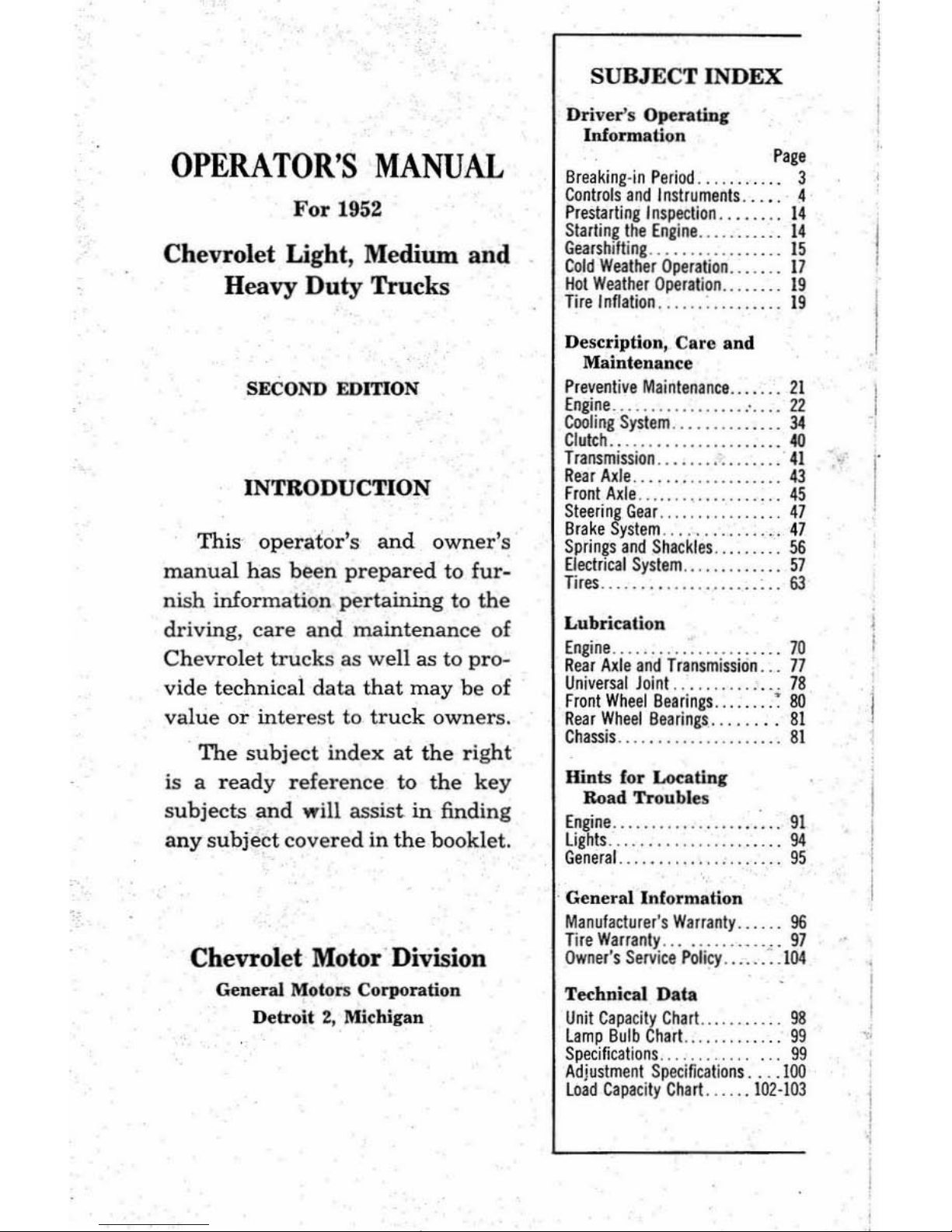
OPERATOR'S
MANUAL
For 19
52
Chevrolet Light, Medium
and
Heavy
Duty
Trucks
SECOND EDITION
INTRODUCTION
This operator's
and
owner's
manual has
been
prepared
to fur-
nish
information
pertaining
to
the
driving, care
and
maintenance
of
Chevrolet
trucks as
well
as
to
pro-
vide te
chni
cal
data that
may be of
value
or
interest
to
truck
owners.
The
subject
index
at
the
right
is a r
eady reference
to
the
key
subjects and will assist in find
ing
any
subject
cove r
ed
in the booklet.
Chevrolet Motor Division
General
Mot
ors
Cor
porati
on
Detroit
2,
Michigan
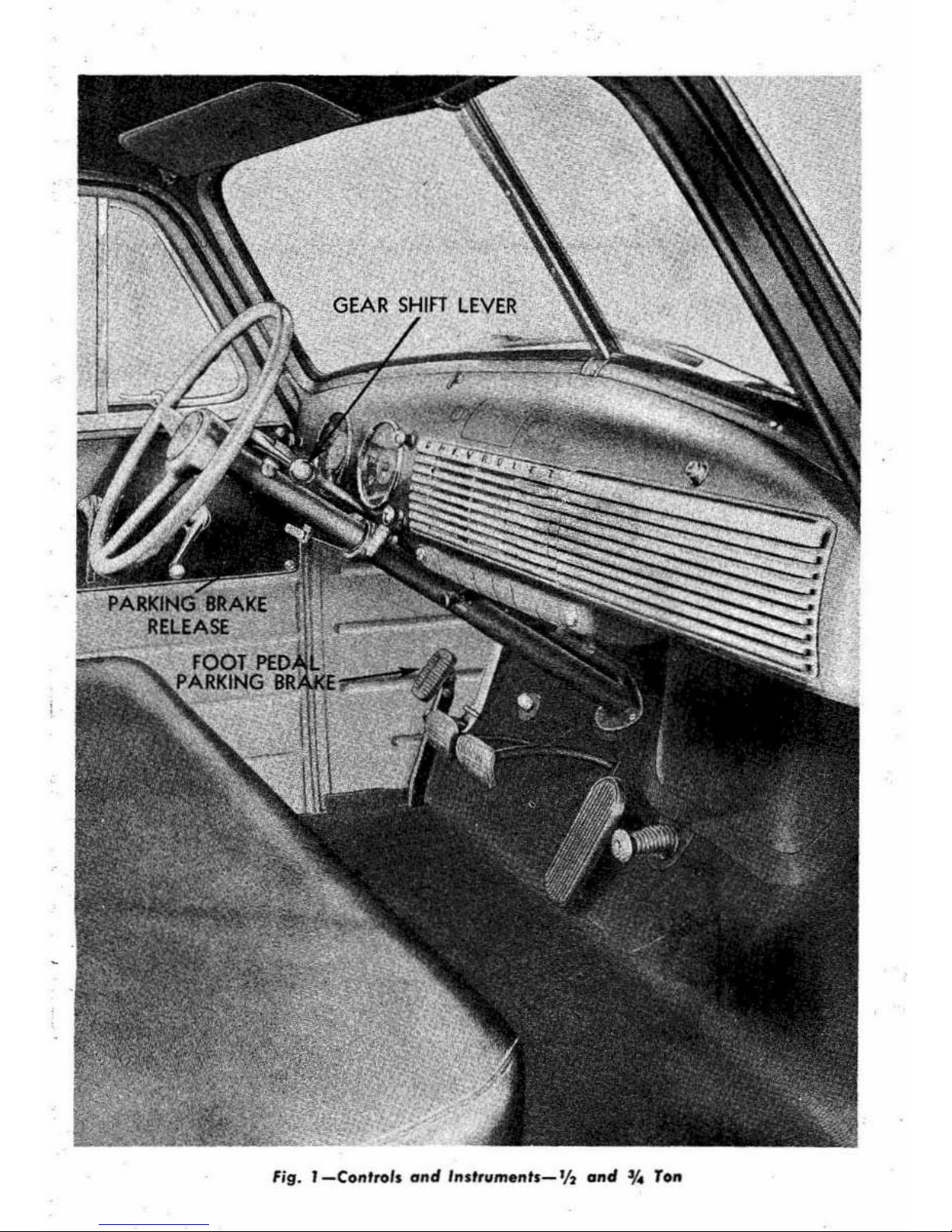
SUBJECT
INDEX
Driver's Ope
ra
tine
Inform
ation
Page
Breaki
ng·inP
eriad......
3
Controls
and
Jnstrumen
ls ..•. 4
Prestarlinglnspection
.
14
SlarlingllleEn'ine
......
....
14
Gearshitting
....
...
...
....
15
Cold
Wealller
Operation
.....
17
tkllWeather
Operation.
19
Tirelnflati
on
...........
.
..
19
Description,
Ca
re a
nd
Maint
enance
Pr
evenliveMaintenance
. 21
E ngi~e
......................
22
Cooling
System
.
34
Clutch.
.
.........
.....
40
T
ransmission
. 41
Rear
Axle
.....
..
.. .
.....
43
F
rontAxle
...
.. ...
45
~~~r~n~y~te:~
..............
...
: ~
SpringsandSh
ackles .....
..
56
El
ectricalSyslem
. 57
Tires
.. .
.....
........
63
Lubr
ica tion
E
ngine_ ....
....
.. .
....
.....
70
Rear Axle
and Transmission
..
77
Universal Joint ...........
__
78
Fro
nt Whe
el
Bearings
.. .. . . ~ 80
R
ear Wheel
Bearings..
81
C
hassis..
81
Hints (or Loca
tin,
Road
Troubl
es
~~~rse_
............
::::::::::::
::
~
General .................
95
Gener
al
Information
Manufaclurer'sWarranly ..... 96
TireWarranty ....
..... ___
..
97
Owner's
Service P
olicy
.......
104
Tec
hnical
Data
UnitCapaci
lyChart.
...
_.
__
.98
lamp
Bulb
Chart .....
....
..
99
Specifi
cations
............
...
99
Adjustment
Specification
s
tOO
loadCapacilyChart .
....
102·103
F
ig.
I-Co"'1OI, ond
l"st,um."Is_'j,
o"d %
To"
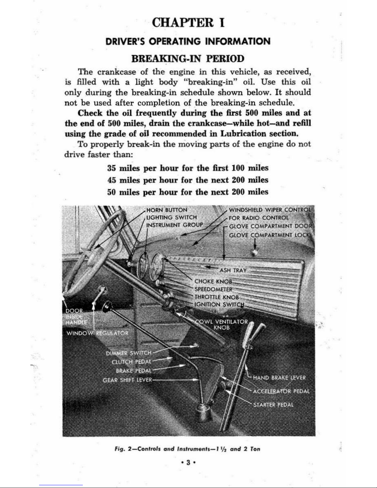
CHAPTER I
DRIVER
'S
OPERATING
INFORMATION
BREAKING-IN PERIOD
The
crankcase
of
the
engine
in
this vehicle, as
rec
eived,
is filled
with
a
light
body
"breaking
-in"
oil.
Use
this
oil
only
during
the
breaking-in
schedule
shown
below.
It
shou
ld
not
be
used
after
completion of
the
breaking-in
schedule.
Check
the
oil
frequently
during
the
first
500 miles
and
at
the
end
of 500 miles,
drain
the
crankcase-while
hot-and
refill
using
the
grade
of
oil recommended
in
Lubrication section.
To
properly
break-in the
moving
parts
of
the
engine
do
not
drive faster than:
35
miles
per
hour
for
the
first
100
miles
45 miles
per
hour
for
the
next
200
miles
50 miles
per
hour
for
the
next
200 miles
f
ig.
2_Co,"I.o1o ond
''''',,,,,,.,,h-'
'h e ....
., 2
To
..
-3'
CONTROLS AND INSTRUMENTS
The
type,
location
and
operation
of
instruments
and
con-
trols
vary
on
different
models
and
makes
of
vehicles;
therefore,
regardless
of
the
experience
an
owner
or
driver
may
have
had
it
is
advisable
to
familiarize
one's
self
with
the
instruments
and
controls,
and
their
use
before
driving
this
new
truck.
The
locations
of
the
various
instruments
and
controls
are
shown
in
figures 1
and
2.
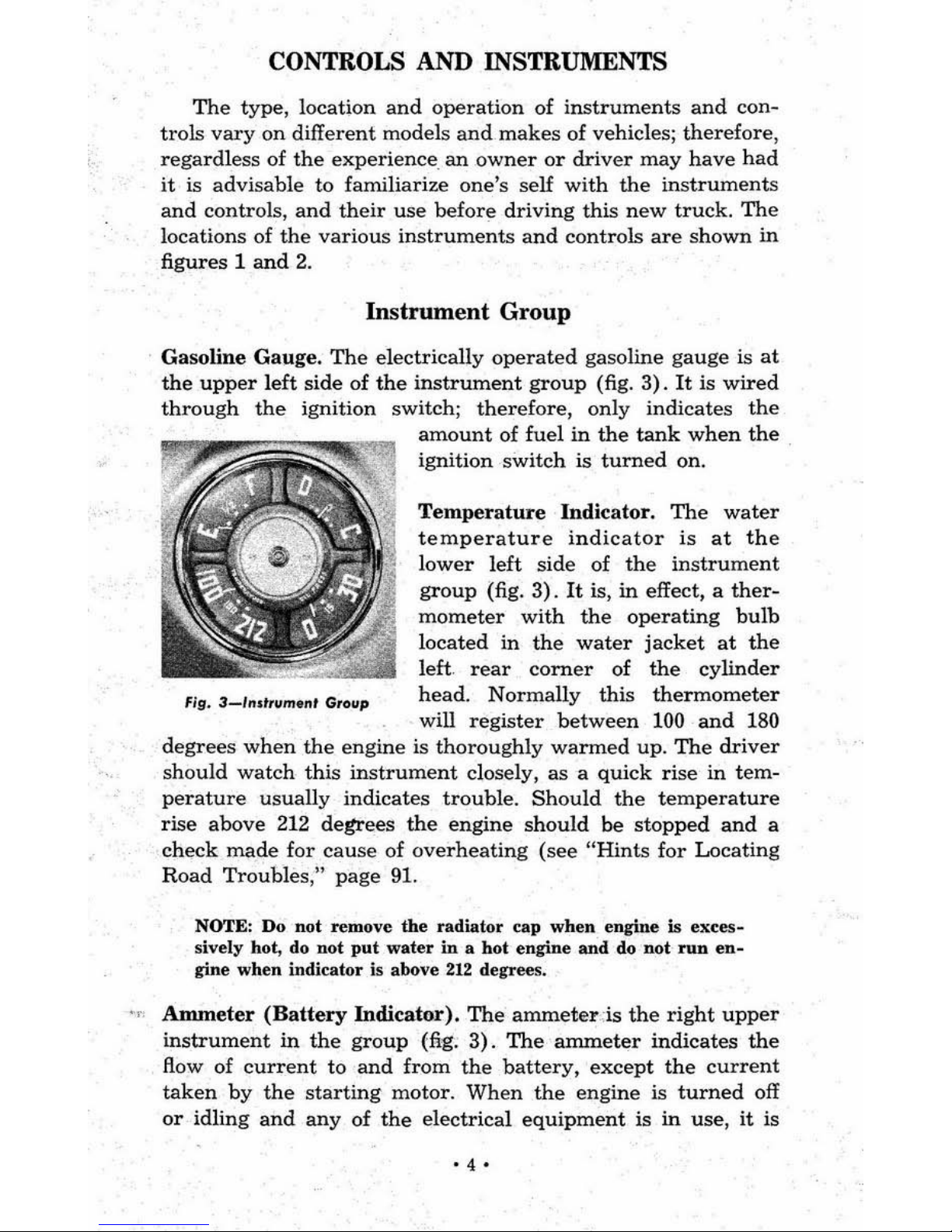
Instrument
Group
Gasoline
Gauge.
The
electrically
operated
gasoline
gauge
is
at
the
upper
left
side
of
the
instrument
group
(fig.
3).
It
is
wired
through
the
ignition
switch;
therefore,
only
indicates
the
fig.
3-J'''tfllmtnt
Grollp
amount
of
fuel
in
the
tank
when
the
ignition
switch
is
turned
on.
Temperature
Indicator.
The
water
temperature
indicator
is
at
the
lower
left
side
of
the
instrument
group
(fig.
3).
It
is,
in
effect, a
ther-
mometer
with
the
operating
bulb
located
in
the
water
jacket
at
the
left.
rear
corner
of
the
cylinder
head.
Normally
this
thermometer
will
register
between
100
and
180
degrees
when
the
engine
is
thoroughly
warmed
up.
The
driver
should
watch
this
instrument
closely,
as a quick
rise
in
tem-
perature
usually
indicates
trouble.
Should
the
temperature
rise
above
212
degrees
the
engine
should
be
stopped
and
a
check
made
for
cause
of
overheating
(see
"Hints
for
Locating
Road
Troubles
,"
page
91,
NOTE: Do not remove
the
radiator
cap
when
engine is
e"ces-
sively hot, do not
put
water
in a bot
engine
and
do Dot
run
en-
gine
when
indicator is above
212
degrees .
•• ' Anuneter
(Battery
Indicator).
The
ammeter
-is
the
right
upper
instrument
in
the
group
(fig.
3).
The
anuneter
indicates
the
flow
of
current
to
and
from
the
battery,
except
the
current
taken
by
the
starting
motor.
When
the
engine
is
turned
off
or
idling
and any
of
the
electrical
equipment
is
in
use,
it
is
'4'
natural
for
the
ammeter
to
show
discharge.
When
the
engine
is
running
at
medium
speed
and
most
of
the
electrical equip..
ment
is
turned
off
the
ammeter
should
show a slight
charge,
depending
on
the
state
of
charge
of
the
battery.
Should
the
ammeter
show
discharge
when
the
truck
is
being
driven
at
medium
speed,
trouble
is
indicated
in
the
charging
system
and
the
battery
will soon become discharged.
Oil
Pressure
Gauge.
This
instrument
is
in
the
lower
right
side
of
the
instrument
group
(fig.
3).
The
oU
pressure
gauge
indi-
cates
whether or-
not
the
oil
pump
is
working,
but
does
not
indicate
the
amount
of oil
in
the
crankcase.
The
pressure
gauge
reading
is
controlled
by
the
engine
speed
and
the
oil
being
used. A
low
reading
is
normal
at
idling
speeds
with
a
warm
engine
and
light
oil;
however,
as
the
engine
speed
is
increased
the
hand
should
move
over
near
the
"IS"
mark.
In
cold
weather
(especially
with
heavy
oil)
the
hand
may
move
over to'
the
"30"
mark
at
comparatively
low
engine
speeds. This indicates
that
the
oil is too
heavy
to
properly
lubricate
the
engine.
NOTE: Do
not
acce l
erate
the
engine
excessive
ly
until
the
oil
is
suffi.
dently
warm
to
permit
a l
ower
pres-
su~.
If
the
gauge
does
not
show
any
pressme,
stop
the
engine
im-
mediately
and
determine
the
cause.
Speedometer.
The
speedometer
is
located
to
the
right
of
the
instru-
ment
group
(fig .. A).
As
the
vehicle
flg.4-Sp
..
dom.'.,
is
driven,
the
hand
moves
around
the
dial
indicating
the
speed
of
the
vehicle
in
miles-per-hour.
The
figures visible
through
the
opening
near
the
center
of
the
speedometer
indicate
the
total
mileage
the
truck
has
been
driven.
This
part
of
the
speedometer
is
known
as
the
odometer.
fIg.
S_/gnitionSwl'd.
Switches
Ignition
Switch.
'The ignition switch
is located
near
the
bottom
of
the
in-
strument
panel
to
the
right
of ·
the
steering
column
(fig. 5).
'5
'
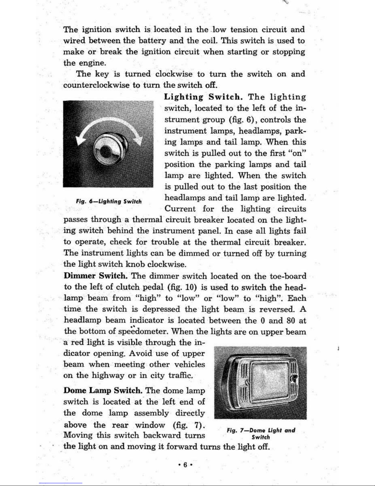
The
ignition
switch
is
located
in
the
.low
tension
circuit
and
wired
between
the
battery
and
the
coil.
This
switch is
used
to
make
or
break
the
ignition
circuit
when
starting
or
stopping
the
engine.
The
key
is
turned
clockwise to
turn
the
switch
on
and
counterclockwise
to
turn
the
switch
off.
Fie·6-UllfltlllgSw
/ICh
Lighting
Switch.
The
lighting
switch,
located
to
the
left
of
the
in-
strument
group
(fig.
6),
controls
the
instrument
lamps,
headlamps,
park-
ing
lamps
and
tail
lamp.
When
this
switch
is
pulled
out
to
the
first
"on"
position
the
parking
lamps
and
tail
lamp
are
lighted.
When
the
switch
is
pulled
out
to
the
last
position
the
headlamps
and
tail
lamp
are
lighted.
Current
for
the
lighting
circuits
passes
through a thermal
circuit
breaker
located
on
the
light-
ing
switch
behind
the
instrument
panel.
In
case
all
lights fail
to
operate,
check
for
trouble
at
the
thermal
circuit
breaker.
The
instrument
lights
can
be
dimmed
or
turned
off
by
turning
the
light
switch
knob
clockwise.
Dimmer
Switch.
The
dimmer
switch
located
on
the
toe·board
to
the
left
of
clutch
pedal
(fig. 10) is
used
to
switch
the
head·
lamp
beam
from
"high"
to
"low"
or
"low"
to
"high".
Each
time
the
switch
is
depressed
the
light
beam
is
reversed.
A
headlamp
beam
indicator
is
located
between
the 0 and
80
at
the
bottom
of
spe~dometer.
When
the
lights
are
on
upper
beam
a
red
light
is visible
through
the
in-
dicator
opening. A void
use
of
upper
beam
when
meeting
other
vehicles
on
the
highway
or
in
city
traffic.
Dome
Lamp
Switch.
The
dome
lamp
switch
is
located
at
the
left
end
of
the
dome
lamp
assembly
directly
:::~g
~is
rse:tc:~:cok:a;:g~u!
fig.
1-~O':;~chUgh'
find
.
the
light
on
and
moving
it
forward
turns
the
light
off.
-6-
Horn
Button.
The
horn
button
is
conveniently
located
at
the
center
of
the
steering
wheel.
Depre
ssing
the
button
blows
the
horn.
Controls
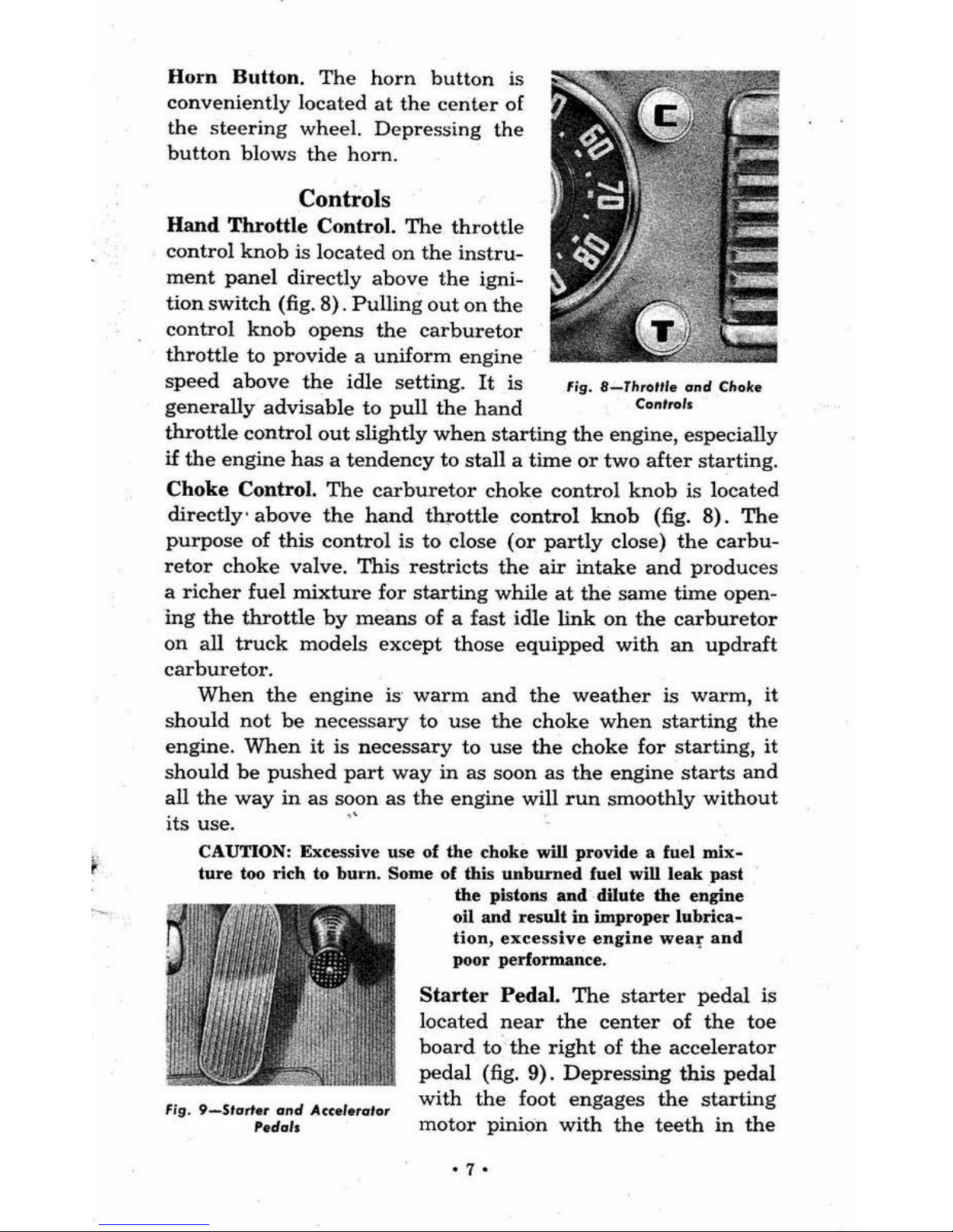
Hand
Throttle
Control.
The
throttle
control
knob
is located
on
the
instru
-
ment
panel
directly
above
the
igni-
tion
switch (fig.
8).
Pulling
out
on
the
control
knob
opens
the
carburetor
throttle
to
provide a uniform
engine
speed
above
the
idle
setting.
It
is
fig.
8_T"ro"'.
ond
Choke
generally
advisable
to
pull
the
hand
Control.
throttle
control
out
slightly
when
starting
the
engine, especially
if
the
engine
has a tendency
to
stall
a time
or
two
after
starting.
Choke
Control.
The
carburetor
choke
control
knob
is
located
directly'
above
the
hand
throttle
control
knob
(fig.
8).
The
purpose
of this
control
is to
dose
(or
partly
close)
the
carbu-
retor
choke
valve.
This
restricts
the
air
intake
and
produc
es
a
richer
fuel
mixture
for
starting
while
at
the
same
time open-
ing
the
throttle
by
means
of
a fast
idle
link
on
the
carburetor
on
all
truck
models
except
those
equipped
with
an
updraft
carburetor.
When
the
engine
is'
warm
and
the
weather
is
warm,
it
should
not
be
necessary
to
use
the
choke
when
starting
the
engine.
When
it
is
necessary
to
use
the
choke
for
starting,
it
should
be
pushed
part
way
in
as
soon as
the
engine
starts
and
all
the
way
in
as
~,on
as
the
engine
will
run
smoothly
without
its use.
CAUTION: Excessive use of
the
choke will provide a fuel
mix-
ture
too rich to
burn.
Some
of
this
unburned
fuel wiD leak past
fig.
9_Starte.
and
Acc.l.ralor
' e
dab
the
pistons
and
dilute
the
engine
oil and result
in
improper
lubrica-
tion,
excessive
engine
wea~
and
poor performance.
Starter
Pedal.
The
starter
pedal
is
located
near
the
center
of
the
toe
board
to
the
right
of
the
accelerator
pedal (fig.
9).
Depressing
this
pedal
with
the
foot
engages
the
starting
motor
pinion
with
the
teeth
in
the
'7'
engine flywheel
and
closes
the
starter
switch to provide
an
electrical
circuit
between
the
battery
and
starting
motor,
there-
by
cranking
the
engine.
The
starting
motor
draws
considerable
current
from
the
battery;
there
fore,
it
sho
uld
not
be
operated
for
more
than
15
seconds
at
a time.
If
the
engine does
not
star
t,
locate the
cause
and
correc
t it before
the
battery
is
run
down.
CAUTION:
The starter
pedal
must
be relellSed
til!
soon as
the
eneine
starts
and
should
never
be depressed
when
the engine is
running
or
serious damage
ma,.
result.
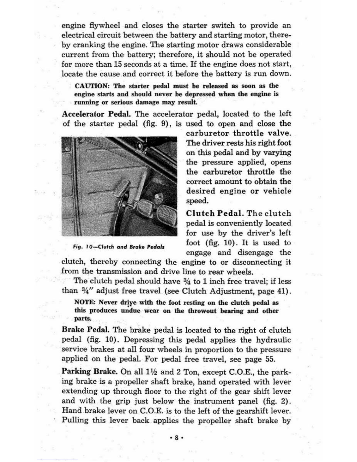
Accelerator
Pedal.
The
accel
erator
pedal, located
to
the
left
of
the
start
er
peda
l (fig.
9),
is
used
to open
and
close
the
Fill.
IO-C/",'(h
and
Itab
'adols
carburetor
throttle
valve.
The
driver
res
ts
his
right
foot
on
this pedal
and
by
varying
the
pressure
applied, opens
the
carburetor
throttle the
correct amount
to
obtain
the
desired
engine
or
vehicle
speed.
Clutch
Pedal.
The clutch
pedal
is
conveniently located
for
use
by
the
driver's
left
foot (fig.
10).
It
is used to
engage
and
disengage the
clutch,
thereby
connecting
the
eng
ine to
or
disconnecting it
from the transmission
and drive
line
to
rear
wheels.
The clutch
pedal should have
;'4
to
1 inch free travel; if less
than
%0"
adjust
free
travel (see
Clutch Adj
ustment, page 41).
NOTE: Never
d'iy
e with the foot
res
tin
l"
on
the
dutcl!
pedal
as
this produces
undue
wear
on the
throwout
bearln,
and
othe
r
pa
rts
.
Brake
Peda
l.
The
brake
pedal is located to
the
right of clutch
pedal (fig.
10).
Depressing
this
pedal
applies
the
hydraulic
service
brakes
at
all
four
wheels in
propertion
to
the
pressure
applied
on
the
pedal.
For
pedal free
trave
l,
see
page
55.
Parking
Brak
e.
On
all11h.
and
2 Ton,
except
C.O.E. ,
the
park-
ing
brake
is a
propeller
shaft
brake,
hand
operated
with lever
extending
up
through
floor
to
the
right
of
the
gear
shift lever
and
with
the
grip
just
below the
instrument
pan
el (fig.
2) .
Hand
brake
lever
on
C.O.E. is to the left of
the
gearshift
lever.
Pulling
this
lever
back
applies the
propeller
shaft
brake
by
• 8 ·
means of mechanical linkage. To release brakes,
grip
the
two
sections of
the
handle
and
pull
lever
back
slightly,
then
move
it forward.
Foot
Operated
Parking
Brake.
Parking
brakes
on
alllh,
%
and
1
ton
models
are
pedal operated.
The
operating pedal (fig. 10)
is located to
the
left
of
the
clutch
pedal
and
pressing down on
this pedal applies
the
rear
wheel
brakes
through
mechanical
linkage
entirely
independent
of
the
hydraulic system. To
release
the
brakes
a release lever is
mounted
on
the
instru-
ment
panel.
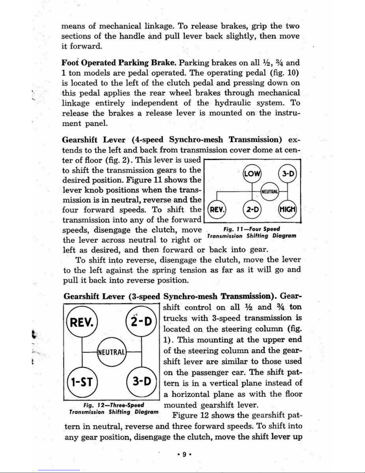
Gearshift
Lever
(4.speed Synchro-mesh Transmission) ex-
tends
to
the
left
and
back
from transmission
cover
dome
at
cen-
ter
of floor (fig. 2). This
lever
is
used
r--------,
to shift
the
tran
smission gears
to
the
desired
position.
Figure
11 shows
the
lever
knob
positions
when
the
trans-
mission is
in
neutral,
reverse
and
the
four
forward
speeds.
To
shift
the
transmission into
any
of
the
forward '-__
----'
___
-'
~~:e~:~e~::~~:;en!~a~l:~ig~to::
rrpn.!~;;i~~
S~~~'~n~a9ram
left as desired,
and
then
forward
or
back
into gear.
To
shift into reverse, disengage
the
clutch, move
the
lever
to
the
left
against
the
spring tension
as
far
as
it
will go and
pull
it
back
into
reverse
position.
Gearshift
Lever
(3-speed
Synchro-mesh
Transmission).
Gear-
shift control
on
all
lh
and
%
ton
trucks
with
3-speed transmission
is
located on
the
steering
column
(fig.
1).
This mounting
at
the
upper
end
of
the
steering
column
and
the
gear-
shift
lever
are
similar
to
those used
on
the
passenger car.
The
shift
pat-
tern
is
in
a vertical plane
instead
of
'-=:""".,....,,---0-==---' a horizontal plane as
with
the
floor
mounted
gearshift lever.
Figure
12 shows
the
gear
shift pat-
tern
in
neutral,
reverse
and
three
forward
speeds. To shift into
any
gear
position, disengage
the
clutch, move
the
shift
lever
up
'9'
or
down
from
neutral
position
and
then
forward
or ba'
ck
into
the
desired
gear.
Cowl
Ventilator
Control
Knob.
This
knob
located
below
the
in-
strument
panel
in
line
with
the
ignition switch (figs. 1
and
2) is
used
to
open
and
close
the
cowl ventilator.
When
the
knob
is
up
toward
the
instrument
panel
the
ventilator
is closed
and
locked.
By
pushing
the
lever
down
and
forward,
the
desired
FJg.I3-Alh
rrar
amount
of
air
circulation
can
be
obtained.
Ash
Tray. A convenient
ash
tray
is
located
in
the
instrument
panel
to
the
left of
the
package
compartment
(fig. 13).
The
tray
is opened
or
closed
by
pulling
back
or
pushing
forward
on
the
hande.
Instrument
Panel
Compartment
Lock.
The
door to
the
convenient
package
compartment
at
the
right
end
of
instrument
panel
is
controlled
by
a lock
above
the
compartment
(fig. 14). Wh en
the
lock
is
unlocked,
depressing
the
lock
cylinder
releases
the
latch
and
the
door
opens.
When
the
lock is
locked
the
cylinder
cannot
be de-
pressed.
The
key
used
for
the
door
lock
and
ignition switch is used
to
lock
and
unlock
the
package
com-
partment.
F/g.
'''-''adr,;;_
Camparlm_n' todr
Keys.
Two
identical
(octagonal
head)
keys
are
furnished
with
each
truck.
These
keys
are
used
for
locking
and
tmlocking
the
right
door,
the
package
compartment
and
ignition.
The
key
number
is
stamped
on a "knockout"
plug
in
each
key
(fig. 15).
T/:le
dealer
and
the
owner
should
make
a
record
of
this
number
so
that
the
"':
=~~
key
can be easily
replaced
in
case
~
j
~.
y
it
is
lost,
and
then
the
"knockout"
plug
should
be
removed
so
that
un-
authorized
personS
cannot
obtain
L-_--:,:-,
•. --:,-:-,_--:.:-.,----'
~~e
k:d:~ber
and
have
a dupli-
·10'
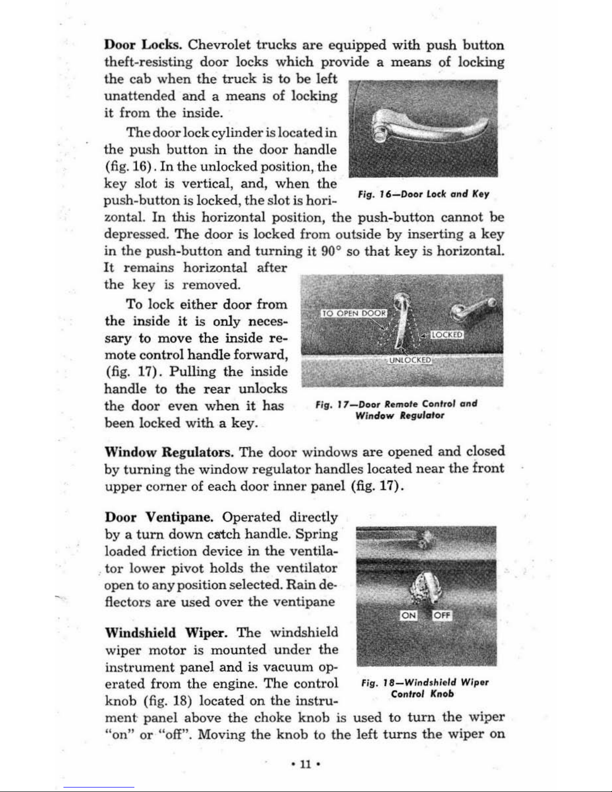
Door Locks.
Chevrolet
trucks
are
equipped
with
push
button
theft-resisting
door
locks which provide a
means
of locking
~n:;t
:
:d:~e:n~h:
~ue~
is
o~
l
~k:;;
""~I'l'!!I""''I''!!'IIIIIJI_
it from
the
inside.
The
door
lock cylinder is located in
the
push
button
in
the
door
handle
(
fig.
16) .
In
the
unlocked position,
the
key sl
ot
is vertical, and,
when
the
push-button
is locked ,
the
slot
is hori- Fig.
16-Doo.
lock
ond
Key
zontaL
In
this horizontal pos ition,
the
push-button
cannot
be
depre
ssed.
The
door
is locked from
outs
ide
by
inserting a
key
in
the pus
h-button
and
turning
it
900 so
that
key
is horizontal.
It
remains horizontal
ah
er
the key is removed.
To lock
either
door
from
the
inside
it
is only neces-
sary
to
move
the
inside
re-
mote control
handle
forward,
(fig. 17).
Pulling
the
inside
handle
to
the
rear
unlocks
the
door
even
when
it has
been locked
with a key.
Fig.
17-Door
lIemole Control
ond
Window IIlfg.,/o'
.....
Window Regulators.
The
door windows
are
opened
and
closed
by
turning
the
window
regulator
handles located
near
the
front
upper
corner
of each door
inner
panel (fig. 17).
Door Ventipane.
Operated
directly
by a
turn
down catch handle.
Spring
loaded friction device in
the
ventila-
tor
lower pivot holds
the
ventilator
open to
any
position sel
ecte
d. Rain de·
flectors
are used
over
the
venti
pane
Windshield Wiper.
The
windshield
wiper
motor
is
mounted
under
the
instrument
panel
and
is
vacuum
op-
erated
from
the
engine.
The
control Fig.
J8_Wind,IIleld
Wiplfr
knob
(fig. 18) located
on
the
instru-
Control Knob
ment
panel above
the
choke
knob is
used
to
turn
the
wiper
"on"
or "off
". Moving
the knob
to
the left
turns
the
wiper
on
'
11'
and moving
it
to
the
right
decrea
ses
wiper
speed
or
turns
it
off completely.
Rear
View Mirror.
An
adjustable
rear
view
mirror
is
mounted
on
the
left side of cowl
in
a position so
that
the
driver
can
get
a
clear
vision along
the
left side of
truck
by
looking
at
the
fIg
.
19-5.'"
Ad/II".'
mirror
through
the
ll!h
door
window.
Seat
Adjuster.
The
entire
seat
as-
sembly
can
be moved
forward
or
back
to
obtain
the
most comfortable
position
for
the
driver. As the
seat
is
moved
forward
it
raises
and
tips for-
ward
and
as
it
is moved
back
it
is
lowered
to
accommodate a tall person.
Moving
the
adjuster
handle
forwa
rd
(fig. 19) releases
the
seat
adjuster
lock so
that
the
seat
assembly
can
be moved for-
ward
or
back
as
desired. Two coil
spri
ngs assist
in
moving
the
seat
forward.
Hood
Lock
and
Safety
Catch.
Th
e hood
is
of
the
"alligator
j
aw"
type
and
is held closed
by
a lock
at
the
front. Thi s lock
"
12'
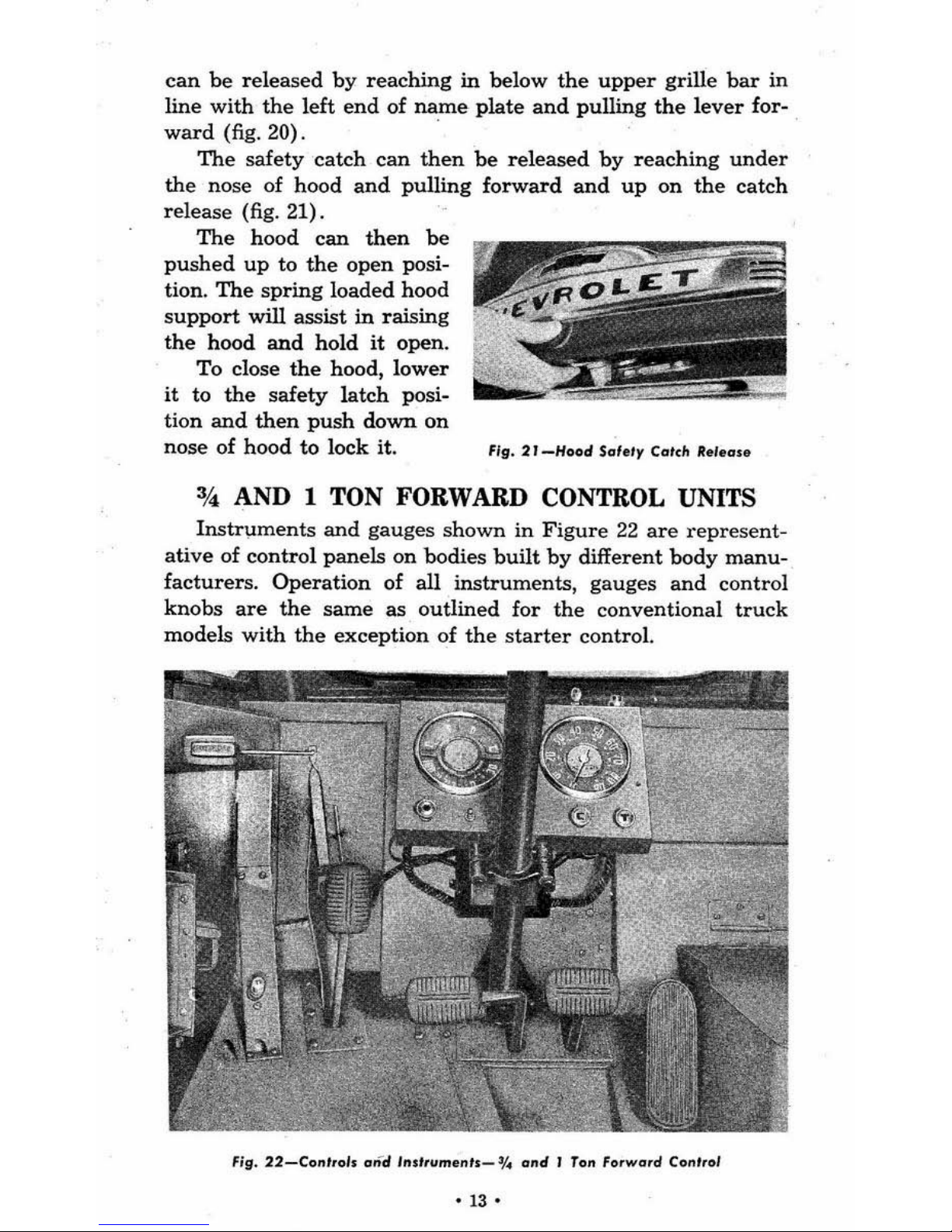
can
be
released
by
reaching
in
below
the
upper
grille
bar
in
line
with
the left
end
of
name
plate
and
pulling
the
lever
for-
ward
(fig. 20).
The
safety
catch
can
then
be
released
by
reaching
under
the nose of hood
and
pulling
forward
and
up
on
the
catch
release
(fig. 21).
The
hood
can
then
be
pushed
up
to
the
open
posi-
tion.
The
spring
loaded
hood
support
will assist
in
raising
the
hood
and
hold
it
open.
To
close
the
hood,
lower
it
to
the
safety
latch
posi-
tion
and
then
push
down
on
nose of
hood
to lock it. F
ig.
2'
-Hood
Saf.,y
COl." R. '.
all
34,
AND 1 TON FORWARD CONTROL UNITS
Instrl,lments
and
gauges
shown
in
Figure
22
are
represent-
ative
of
control
panels
on
bodies
built
by
different
body
manu-
facturers.
Operation
of
all
instruments,
gauges
and
control
knobs
are
the
same
as
outlined
for
the
conventional
truck
models
with
the
exception
of
the
starter
control.
Fig.
22-Co,,',ol.
and
I"II,ume,,'s_
0/.
a"d
,
Ton
fo,wa,d
Co
nl,ol
-13-
The
starter
control
is of
the
push
button
solenoid
type
with
the
star.ter
button
located
on
the
instrument
panel
face
or
top
of panel. Rel
ease
the
starter
button
as
soon
as
the
engine starts
and
never
press
the
button
with
the
engine
running
or
serious
damage
may
result.
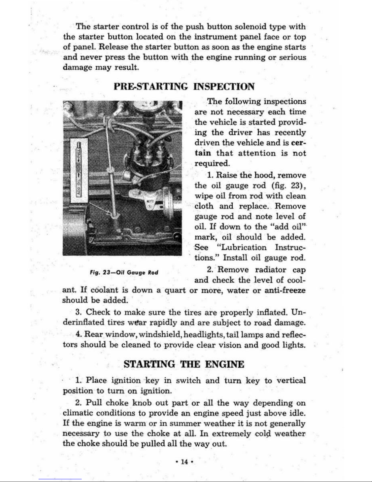
PRE-STARTING
INSPECfION
~19.
23-011
Gaugelfod
The
following inspections
are
not
necessary
each
time
the
vehicle is
started
provi
d-
ing
the
driver
has
recently
driven
the
vehicle
and
is
cer-
tain
that
attention
is
not
required.
1.
Raise
the
hood,
remove
the
oil gauge r
od
(fig. 23),
wipe
oil
from
rod
with
clean
cloth
and
replace. Remove
gauge
rod
and
note
lev
el of
oil.
If
down
to
the
"add
oil'"
mark,
oil
should
be
added.
See "Lubri
cation
Instruc-
. tions." Install oil
gauge
rod.
2.
Remove
radiator
cap
and
check the level of cool-
ant.
U c60lant is down a
quart
or
more,
water
or
anti
-free
ze
should
be added.
3.
Check
to
make sure
the
tires
are
properly
inflated.
Un-
derinftated
tires
w~r
rapidly
and
are
subject
to
road
damage.
4.
Rear
window, windshield,headlights,
tail
lamps
and
reflec-
tors
should
be
cleaned
to
provide clear
vision
and
good lights.
STARTING THE ENGINE
1.
Plac
e ignition '
key
in
switch
and
turn
key
to
vertical
position
to
turn
on
ignition.
2.
Pull
choke
knob
out
part
or
all
the
way
depending
on
climatic conditions to provide
an
engine
speed
just
above
idle.
If
the
engine
is
warm
or
in
summer weather
it
is
not
generally
nec
essary
to
use
the
choke
at
all.
In
extremely
col9.
weather
the
choke
should
be
pulled
all
the
way
out.
'14'
3.
Make
sure
the
transmission shift
lever
is
in neutral. De-
press
the
clutch
pedal
to
relieve
the
load
in
the
transmission.
4.
Step
on
starter
pedal,
or
on
Forward
Control models press
button, to
crank
engine. Remove foot from
starter
pedal
or
finger
from
starter
button
as
soon
as
engine starts.
If
engine does
not
start
in
15 seconds, release
pedal
or
button
and check to see
that
the
above operations
have
been
performed
correctly.
5.
As
soon
as
engine starts,
push
choke
knob
in
part
way
and
adjust
throttle
for smooth idle.
6.
Note oil gauge
and
ammeter
readings. Amm
eter
sho uld
show some
charge
unless engine is idling slowly. Oil gauge
s
hould
show some
pre~ure.
In
unusually
cold
weather
the
oil
gauge
needle
may
go
over nearly
to 30.
If
so,
run
the
engine
ju
st above idling speed
until
the
pressure
drops to
around
15
before driving vehicle.
The
choke
knob
should
be
pushed
in
all
the
way
as
soon
as
the
engine is sufficiently
warmed
up.
GEARSHIFTING
Starting
the
Vehicle
1.
Push
clutch
pedal down to disengage
the
clutch.
2.
Move gearshift lever
into low
gear
position.
(If
4-speed
transmission
see
Figure
11
,
or
if
3-speed
transm
ission see
Figure
12.)
3.
Release ·
the
parking
brake.
4.
Push
down slightly
on
acce
lerator
pedal
and
at
the
same
time slowly engage
the
clutch.
Continue
to depress
the
accel-
er
ator
pedal
until
the
'Ve
hicle is moving.
Shifting
to
Highet
Gears.
1.
Depre
ss
clutch
pedal
and
release accelerator
at
the
same
time. Move
the
shift
lever
into
neutral
and
then
to
the
next
higher
gear.
See
shifting diagrams,
Figures
11
and
12.
2.
Accelerate
the
engine
slightly
and
slowly engage
the
clutch.
3.
Accelerate
the
engine
to
about % maximum
engine speed
before shifting to
the
next
high
er
gear
and
proceed
as outlined
above.
Shifting
to
Reverse
(4-speed
tran
smission)_
The
vehicle
must
not
be moving forward
when
shifting
to
-15'
1.
Depress
clutch
pedal
to
disengage
the
clutch
.
2. Move
shift lever
across
neutral
to left,
against
the
spr
ing
tension as
far
as
it
will go. Move
lever
back
into
reverse
(fig.
11).
3.
If. parking
brake
is on, release
the
brake.
4.
Push
down
slightly
on
accel
erator
pedal
and
at
the
same
time
slowly engage
the
clutch.
Control
the
vehicle
speed
with
the
accelerator.
Shift
ing to
Reverse
(3-speed transmission).
The
vehicle s
hould
not
be moving f
orward when
shifting
to
rev
erse
.
1.
Depre
ss
clutch
pedal to. disengage
the
clutch.
2.
Raise
shift lever
up
across ne
utral
and
forward
into
reverse
position. (fig. 1
2).
3.
If
parking
brake
is on,
rel
ease
the
brake.
4.
Push
down slig
htly on
accelerator
pedal
and
at
the
same
time
slowly engage
the
clutch.
Control
the
vehicle
speed
with
the
accele
rat
or. .
Shifting
to
Lower
Gears
To
obtain
more
pulling
power
for
negotiating
bad
roads
or
climbing hills,
or
to
travel
at
unusually slow
speed
it
is
sometimes
necessary
to
shift
to
lower
transm
ission gears.
The shift
from high to second
with
the
3-speed
synchro-me
sh
transmission
or
from
high
to
third
or
third
to second
with
the
4-speed
synchro-mesh
transmission
is
aeeomplished
in
the
same
manner
as un-shifting.
The
following
procedure should be
used
when
shifting
the
3-speed
or
4-speed
transmission
from
second
to
low.
1. Disengage
the
clutch
and shift
the
trans
mission
into
neutral
while
maintaining
enough
pressure
on
acce l
erator
to
noticeably
increa
se
engine
speed.
2.
Enga
ge
clutch
and
quickly
disengage
it
again.
3.
Shift
into
the
next
lower
gear
quickly
and
then
gradua
lly
engage clutch.
Shifting
Two-Speed
Rear
Ax
le
The
vacuum
shift
ma
kes this
operation
compar
atively
simple as
it
is
unnecessary
to declutch while shifting.
The
-I
S-
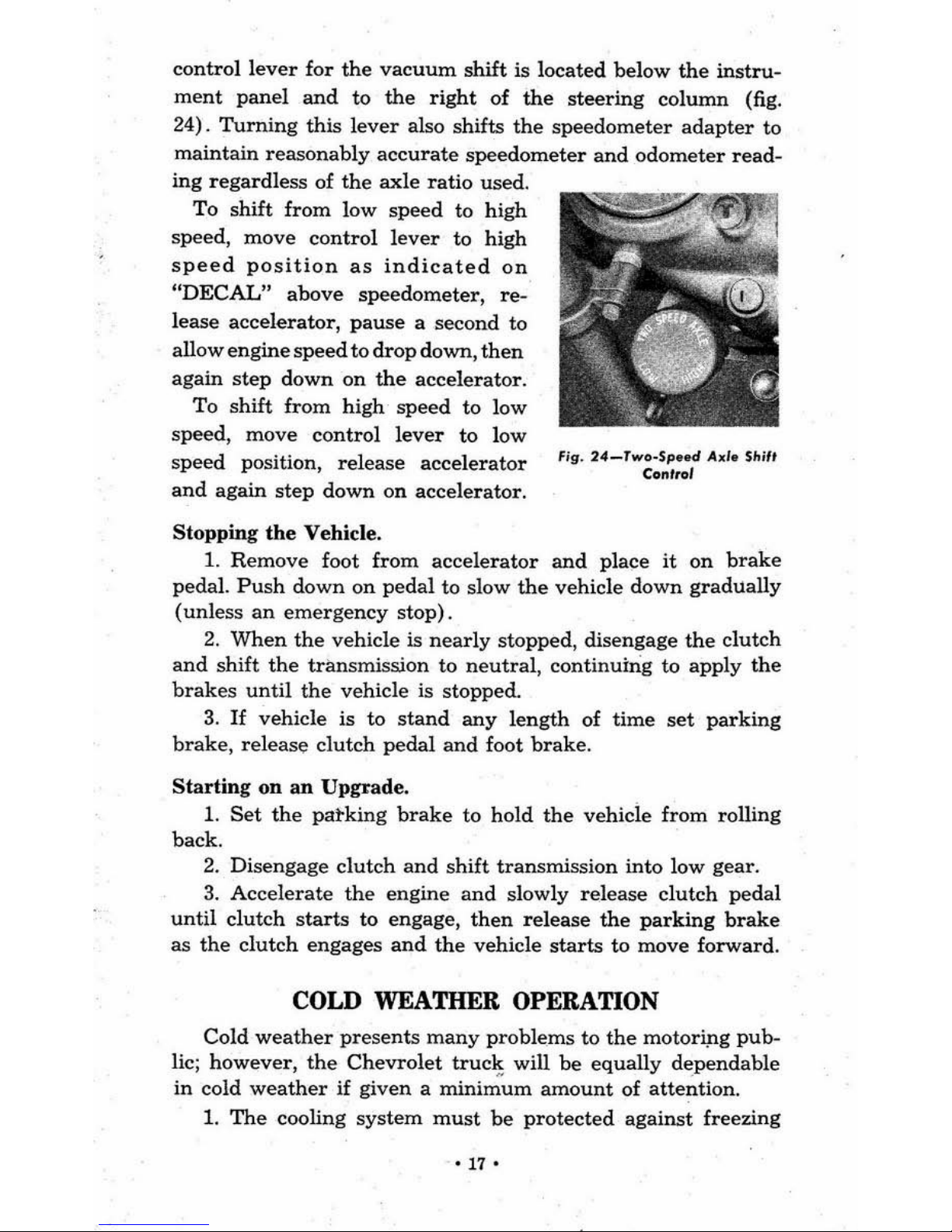
control
lever
for
the
vacuum
shift
is
located
below
the
instru-
ment
panel
and
to
the
right
of
the
steering
column
(fig.
24).
Turning
this
lever
also shifts
the
speedometer
adapter
to
maintain
reasonably
accurate
speedometer
and
odometer
read-
ing
regardless
of
the
axle
ratio
used.
To
shift
from
low
speed to high
speed,
move
control
lever
to high
speed
position
as
indicated
on
"DECAL"
above
speedometer,
re-
lease accelerator,
pause
a second to
allow
engine
speed
to
drop
down,
then
again
step
down
on
the
accelerator.
To
shift
from
high
speed
to
low
speed,
move
control
lever
to
low
speed
position,
release
accelerator
and
again
step
down
on
accelerator.
Stopping
the
Vehicle.
Fig.
24_Two_Sp
.. d Axi
.
Shi',
Con'tol
1.
Remove
foot
from
accelerator
and
place
it
on
brake
pedal.
Push
down
on
pedal
to slow
the
vehicle
down
gradually
(unless
an
emergency
stop).
2.
When
the
vehicle is
nearly
stopped, disengage
the
clutch
and
shift
the
transmission
to
neutral,
continuing
to
apply
the
brakes
until
the
vehicle is stopped.
3.
If
vehicle
is
to
stand
any
length
of
time
set
parking
brake,
release
clutch
pedal
and
foot
brake.
Starting
on
an
Upgrade.
1.
Set
the
pat-king
brake
to hold
the
vehicle from rolling
back.
2.
Disengage
clutch
and
shift
transmission
into
low
gear.
3.
Accelerate
the
engine
and
slowly
release
clutch
pedal
until
clutch
starts
to engage,
then
release
the
parking
brake
as
the
clutch
engages
and
the
vehicle
starts
to move
forward.
COLD WEATHER OPERATION
Cold
weather
presents
many
problems
to
the
motoripg
pub-
lic; however,
the
Chevrolet
truck
will
be
equally
dependable
in
cold
weather
if given a
mini~~m
amount
of
attention.
1.
The
cooling
system
must
be
protected
against
freezing
'17
-
by
the use of anti-freeze solutions (see "Cooling
System"
and
"Anti-Freeze")'
or
the system must be
drained
at
the lower
right
corner
of
radiator
and
the
left
rear
corner
of cylinder
block each time
the
vehicle is to
stand
any
length of time.
2.
Light oil should be
used
in
the
engine (see "Engine
Lubrication") .
3.
The
battery
should be
kept
fully charged to provide the
additional power necessary to
crank
a cold engine
and
furnish
a good spark. A discharged
battery
will freeze in extremely
cold
weather
which will
make
battery
replacement necessary.
4.
The
carburetor,
fuel
pump
and
fuel
tank
should
be
kept
free from
water
which will freeze
and
restrict
fuel flow.
5.
The ignition system should be
kept
in
good condition.
6.
Assuming
that
the
above items
have
been
given
normal
attention, the engine should
start
promptly, even in extremely
cold weather,
by
following this simple procedure:
a.
Turn
on ignition.
b.
Pull
choke knob
all
the
way
out.
c.
Depress foot accelerator slowly a few times.
d. Disengage
the
clutch.
e.
Step
on
starter
pedal
or
push
button
on
Forward
Control.
f.
Release
starter
as soon as engine
starts
and
push
choke
knob
in
slightly.
g.
Regulate choke to provide a fast idle and
gradually
push
choke knob
in
as engine warms up.
h. In
abnormal~
cold
weather
the
engine should be
run
slightly above idling speed for a few minutes to
warm
up
the oil before driving
the
truck.
NOTE: Never
race
the
e..,me
until
the
oil
pUle
needle wil l sta,.
.round
15.
7.
The
Chevrolet cooling system is designed to properly
cool
the
engine
under
most severe operating conditions in hot
weather. A
thermostat
is used
in
the system to
restrict
the
water
circulation until
the
engine
warms
up.
In
very
cold
weather
and
under
certain driving conditions such as house-
to-house delivery where
the
engine idles a lot
or
is stopped
·18·
and
started
frequently,
the
production
thermostat
does
not
maintain
high
enough
temperature
for best
economy
and
per-
formance.
In this
case a
higher
temperature
thermostat
should
be
us ed
or
part
of
the
radiator
area
covered.
HOT WEATHER OPERATION
Hot
weather
does
not
generally
present
as
many
problems
as cold
weather;
however, a little
special atte
ntion
will
pay
dividends
in
the
form
of
economy
and
convenience
.
1.
Check
the
radiator
regularly
for sufficient coolant as the
rate
of
evaporation
is
higher
in
hot
weather.
2.
Make
sure
the
fan
belt
is
in
good
condition
and
properly
adjusted.
3.
Keep the
radiator
area
free
of
bugs
and
other
things
that
restrict
air
circulation.
4.
Have the
water
level
in
the
battery
checked
at
lO-day
intervals
or
oftener,
if
necessary.
5.
Starting
a cool en
gine
in
hot
weather
does
not
present
a
problem
and
the
procedure
outlined
under
"Starting
the
Engine"
should
be followed.
_ A
hot engine
is easily flooded
and
may
start
hard.
If
the
carburetor
is
flooded
proceed
as follows:
a.
Turn
on
ignition.
b.
Pull
hand
throttle
knob
out
about
J.h".
c.
Do
not
pull
choke
knob
out
or
step
on
accelerator.
d.
Depress
sflarter
pedal
or
starter
button
without
depressing
accelerator.
e.
When
engine
starts,
release
starter,
but
do
not
accelerate
engine.
f.
Regulate
hand
throttle
knob
for
desired
engine
speed.
If
the
engine
still
does
not
start
look
for
trouble
in
the
fuel
pump
or
ignition
system.
.
TIRE INFLATION
Tire
pressures
should
be checked"
at
least
once a week
and
inflated
according
to the following table.
-19-
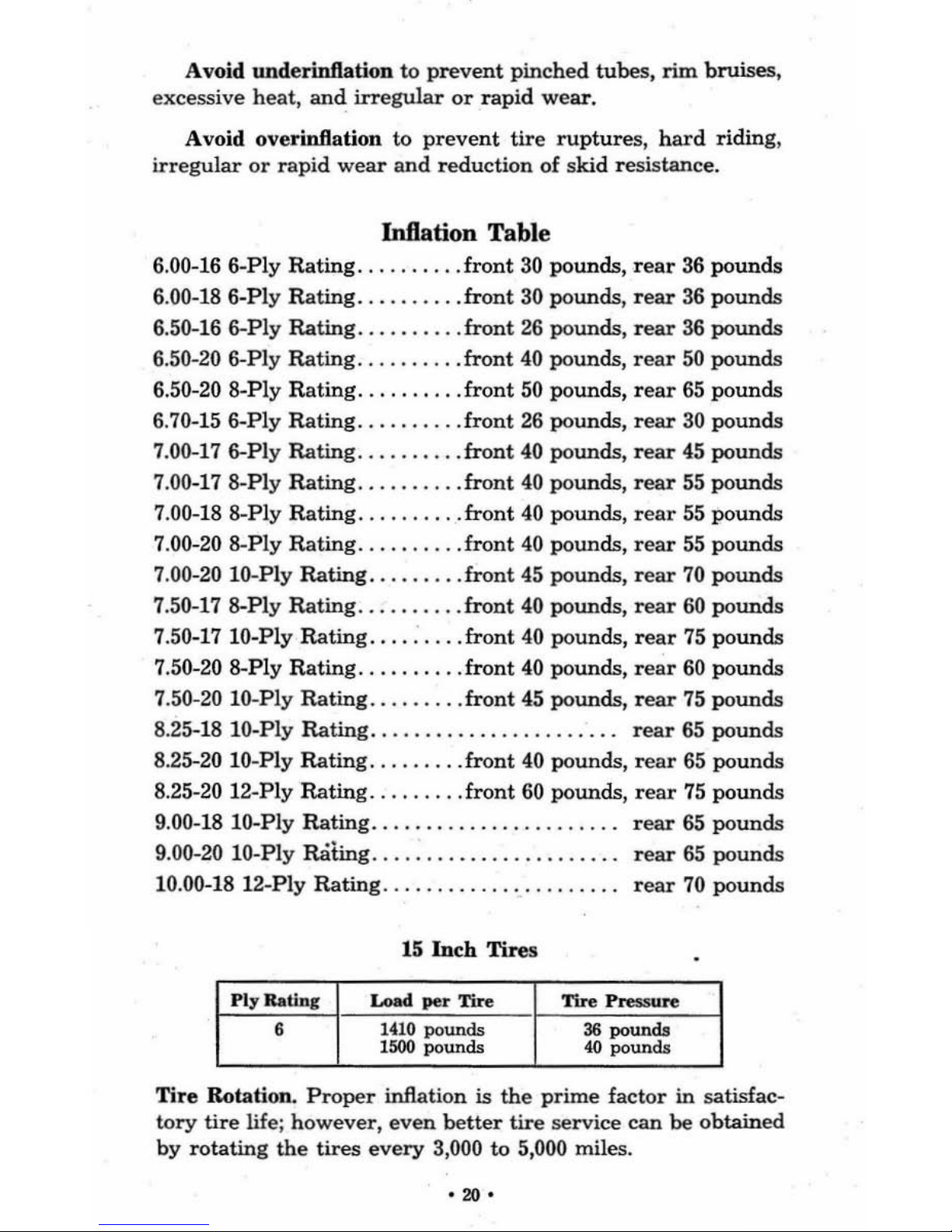
Avoid underinftation to
prevent
pinched tubes,
rim
bruises,
excessive heat,
and
irregular
or
rapid
wear.
Avoid over inflation to
prevent
tire
ruptures, hard
riding,
irregular
or
rapid
wear
and
reduction of skid resistance.
Inflation Table
6.00-16 6-Ply
Rating..
. . front
30
pounds, r
ear
36 pounds
6.00-18 6-Ply
Rating
..........
front
30 pounds,
rear
36
pounds
6.50-16 6-Ply
Rating..
.
..
front
26
pounds, r
ear
36
pounds
6.50-20 6-Ply
Rating..
.
.front
40
pounds,
rear
50
pounds
6.50-20 8-Ply
Rating
.........
front
50
pounds,
rear
65
pounds
6.70-15 6-Ply Rating
.....
front
26
pounds,
rear
30
pounds
7.00-17 6-Ply Rating
.......
. .
front
40 pounds, r
ear
45
pounds
7.00-17 8-Ply
Rating
..........
front
40
pounds,
rear
55
pounds
7.00-18 8-Ply
Rating
.........
front
40
pounds,
rear
55
pounds
7.00-20 8-Ply
Rating
..........
front
40
pounds,
rear
55
pounds
7.00-20 10-Ply Rating
.........
front 45 pounds,
rear
70
pounds
7.50-17 8-Ply
Rating..
.
.front
40
pounds,
rear
60
pounds
7.50-17 10-Ply Rating
.........
front 40 pounds,
rear
75
poun
ds
7.50-20 8-Ply Rating. .
.front
40
pounds,
rear
60 pounds
7.50-20 10-Ply Rating
........
front
45 pounds,
rear
75
pounds
8.25-18
10-Ply
Rating.
.
rear
65 pounds
8.25-20 IO-Ply
Rating
........
front
40 pounds,
rear
65
pounds
8.25-20 12-Ply Rating
.........
front
60 pounds,
rear
75
pounds
9.00-18 10-Ply
Rating.
. .
rear
65
pounds
9.00-20 10-P
ly
Rating..
rear
65
pounds
10.00-18
l2-Ply
Rating
..
rear
70
pounds
15
Inch
Tires
Tire
Rotation.
Proper
inflation is the
prime
factor
in
satisfac-
tory
tire
life; however,
even
better
tire
service can be obtained
by
rotating
the
tires
every
3,000 to 5,000 miles.
·20·
CH
AP
TER n
DESCRIPT
ION,
CARE
AND
MAINTENANCE
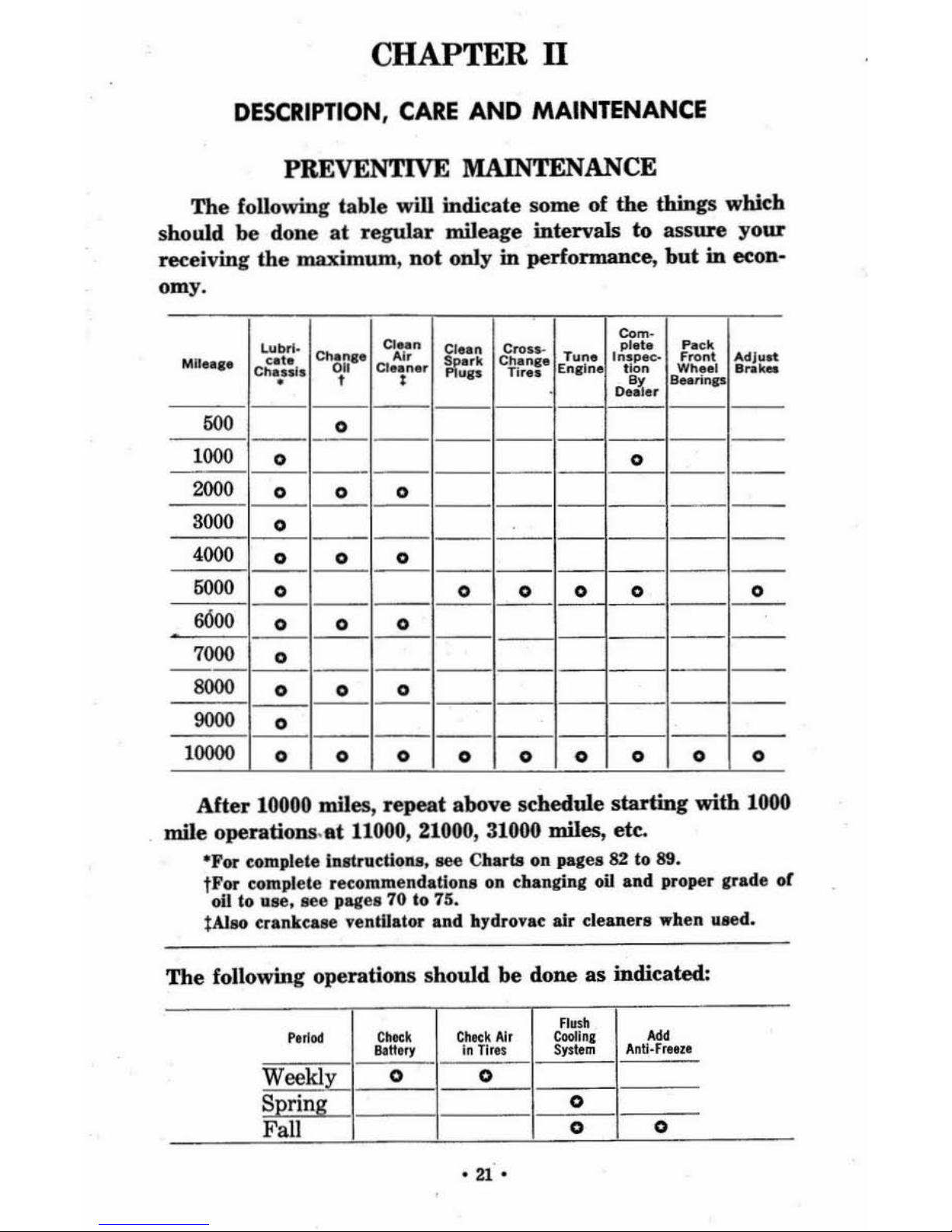
PREVENTIVE MAINTENANCE
The
following table
will
indicate
som
e of
the
things
which
should be do
ne
at regular
mileage intervals to
assure
your
rec
eiving
the
maximum
, Dot only
in
perfonnance
. but
in
econ-
om
y.
M
U....
L~~.
Chan
a'
CI~n
i("
~~
8:~:-.
Tlln
. .
a.
r
~"n~
Ad •
.l~~
CII'.'''I
~
'
CI.~n
..
~"p
Tir ..
Enaln
t
~;
s:.~
,.-
------------
.1~
0
,.11.
___
_
~--
-_o_------
I-I-
___
_
~
_o_--------
I-I----'!...-
___
_
2000
000
~
°
===
:= 1-
==
~
_°
___
° ___ °
____
_
1--
-----
6000
_ 0
____
_
__ 0 ___ 0_1
-"-
_ 0 _
___
0 _
~
_o_-_o_-_o----I------
-
~~
_o_-------
-I-I-----
8000
_ 0
___ 0 ___ 0 ____
1-
-----
-
9000
_ 0
____
_____
1-
--
1--1--
1
0000
000000000
After 10000
miles,
repeat
above schedule
starting
with
1000
mile
operations.at
11000, 21000, 31000 miles,
etc
.
-For complete in .flru
cUotUl, see Charts
on pages 82 to 89.
tFor complete recommenda
Uon
a on changing oil and proper grade or
01
1 to u
se.
see
pag
es
70 to 75.
lAlso era nkease l'cotllator and hydrovac ai r cleane
rs
when aled.
The
following
operation
s sho
uld
be
done
as
indicated:
Fla
sh
CooIlnt
Add
a.
tt.
ry
in Ti
res
Syste
m
An
~·fr"l l
~
0 0
I-----=-
==
~~~
:n
g
1-
--
-
-+-
-0-
.".
ENGINE
Description.
The
Chevrolet
six
cylinder
valve-in-head
truck
engines
are
the
prime
factor
in
Chevrolet's
outstanding
per-
formance
and
economy.
They
are
designed to give l
ong
trouble-
free life. Chevrolet's four-way engine lubrication system pro-
vides
the
correct
amount
of
lubr
ication
to
all
moving
parts
.
Full
stroke
length
water
jackets, surroundin
g
all
cylinders,
provide
uniform
cooling
and
prevent cylinder
distortion
which
wou
ld
cause
undue
wear
and
poor oil economy.
The
water
passages
in
the
cylinder block
and
cylinder
head
properly
direct
the flow of
water-to provide
unifonn
cooling of
the
engine
(fig. 25).
Care.
The
engine oil level s
hould
be
checked
each
time
fuel
is
purchased
and
oil
added when
necessary.
(See
Lubrication
Section.)
The
engine
should
be inspected occasionally for oil
and
water leaks
and
the
necessary
repairs
made.
Keep
the
engine
clean externally.
Valve
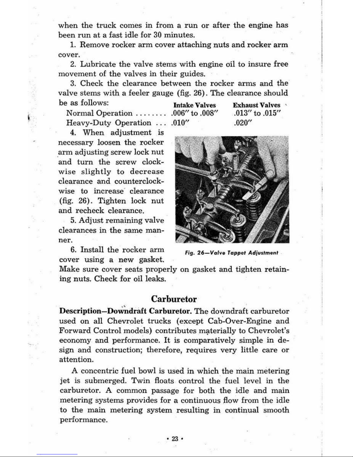
Tappet
Adjustment.
Valve
tappet
adjustment
shou
ld
be
c
hecked
when
the
engine is thoroughly
warmed
UP.
preferably
fI,
.
2S-Wot"
flow
""011,,,
Coo/in.
5,..1
....
•
22·
when
the
truck
comes
in
from a run
or
after
the
engine
has
been
run
at
a fast
idle
for
30
minutes.
1.
Remove
rocker
arm
cover
attaching
nuts
and
rocker
arm
cover.
2.
Lubricate
the
valve
stems
with
engine
oil
to
insure
free
movement
of
the val
ves
in
their
guides.
3.
Check
the
clearance
between
the
rocker
anus
and
the
valve
ste
ms
with a feeler
gauge
(fig. 26).
The
clearance
should
be
as
follows:
Normal Operation.
Heavy-Duty
Operation
.
4.
When
adjustment
is
necessary
loosen
the
rocker
arm
adjusting
screw
lock
nut
and
turn
the
screw
clock-
wise
slightly
to decrease
clearance
and
counterclock
-
wise to
increase' clearance
(fig. 26).
Tighten
lock
nut
and
recheck
clearance.
5.
Adjust
remain
ing
valve
clearances
in
the
same
man-
6.
Install
the
rocker
arm
cover
using
a
new
gasket.
Intak
e Valves
.006"
to
.008"
.010"
Exhaust
Valves '
.013"
to
.015"
.020"
Make
sure
cover
seats
properly
on
gasket
and
tighten
retain-
ing nuts.
Check
for
oil l
eaks.
Carburetor
Description-Do~draft
Carburetor.
The
downdraft
carburetor
used
on
all
Chevrolet
trucks
(except
Cab~Over-Engine
and
Forward
Control
mode
ls)
contributes
m~terially
to
Chevrolet's
economy and
performance.
It is
comparatively
simple
in
de-
sign
and
constructio
n;
therefore,
requires
very
little
care
or
attention.
A
concentric fuel bowl
is
used
in
which
the
main
metering
jet
is
submerged.
Twin
floats
control the
fuel
level in
the
carburetor.
A commo n
passage
for
both
the idle
and
main
metering
systems
provides
for a continuous
flow from
the
idle
to
the
main
metering
system
resulting
in
continua
l s
mooth
p
erfo
rmance.
'
23'
This
carburetor
has a vacuum
controlled
power
jet
and
a
throttle
operated
accelerator
pump
to
aid
in
pro
viding
the
desired
economy
and
performance.
Description-Updraft
Carburetor.
The
updraft
carburetor
used
on.
the
Cab-Over-Engine
and
Forward
Control
trucks
is
mounted
below
the
manifold.
It
is
equipped
with a vacuum
controlled
power jet
and a throttle
operated
accelerating
pump
to
aid
in
providing the
desired
economy
and
performance.
Care.
Tighten
the
carburetor
to
manifold
and
the
manifold
to
cylinder
head
stud
nuts
to
prevent
air
leaks.
Keep
the
car-
buretor
clean
externally
and
have
it
comple
tely
overhauled
at
regular
intervals
so
that
foreign
matter
in
the
carburetor
and
worn
parts
will
not
affect
correct
carburetion.
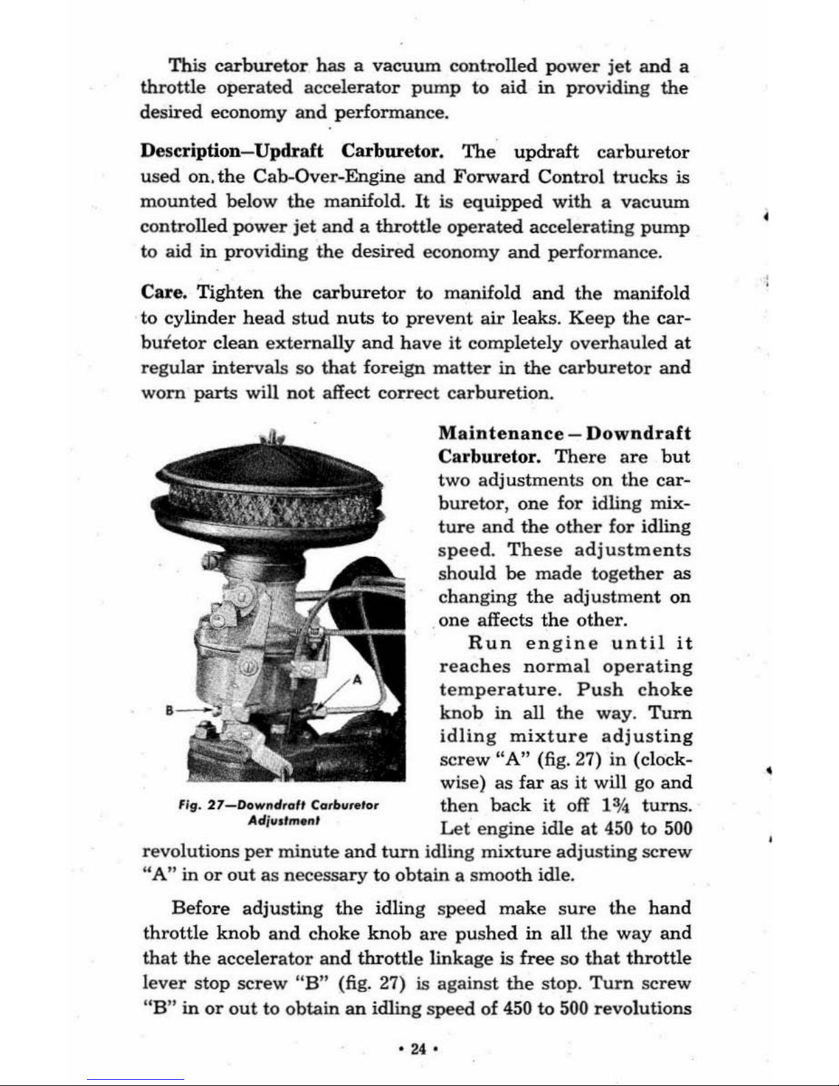
' Ig.
27_Downd,
.. f, C
..
,b
....
to,
Adj
..
.,men'
Maintenance
-
Downdraft
Carburetor.
There
are
but
two
adj
ustments
on
the
car-
buretor,
one
for
idling
mix-
ture and
the
other
for
idling
speed.
These
adjustments
sho
uld
be
made
together
as
changing
the
adjustment
on
one
affects
the
other.
Run
engine
until
it
reaches
normal
ope
rating
temperature.
Push
cho
ke
knob
in
all
the
way.
Turn
idling
mixture
adjusting
screw
"A"
(fig. 27) in (clock-
wise)
as
far
as
it will go
and
then
back
it
off 1
0/4
turns.
Let
engi
ne
idle
at
450 to 500
revolutions per
minute
and
turn
idling
mixture
adjusting
screw
"A"
in or
out
as
necessary
to
obtain
a smoo
th
idle.
Before
adjusting
the
idling speed
make
sure the
hand
throttle
knob
and
choke
knob
are
pushed
in
all
the
way
and
that
the
accelerator
and
throttle
linkage
is
free
so
that
throttle
l
ever
stop
screw
"B"
(fig. 27) is against
the
stop .
Turn
screw
"
B"
in
or
out
to
obtain
an
idling
speed
of 450
to
500 r
evo
lutions
.".
per
minute.
If
necessary
readjust
idling
mixture
screw
"A"
as
explained
above
to
obtain a smooth
idle.
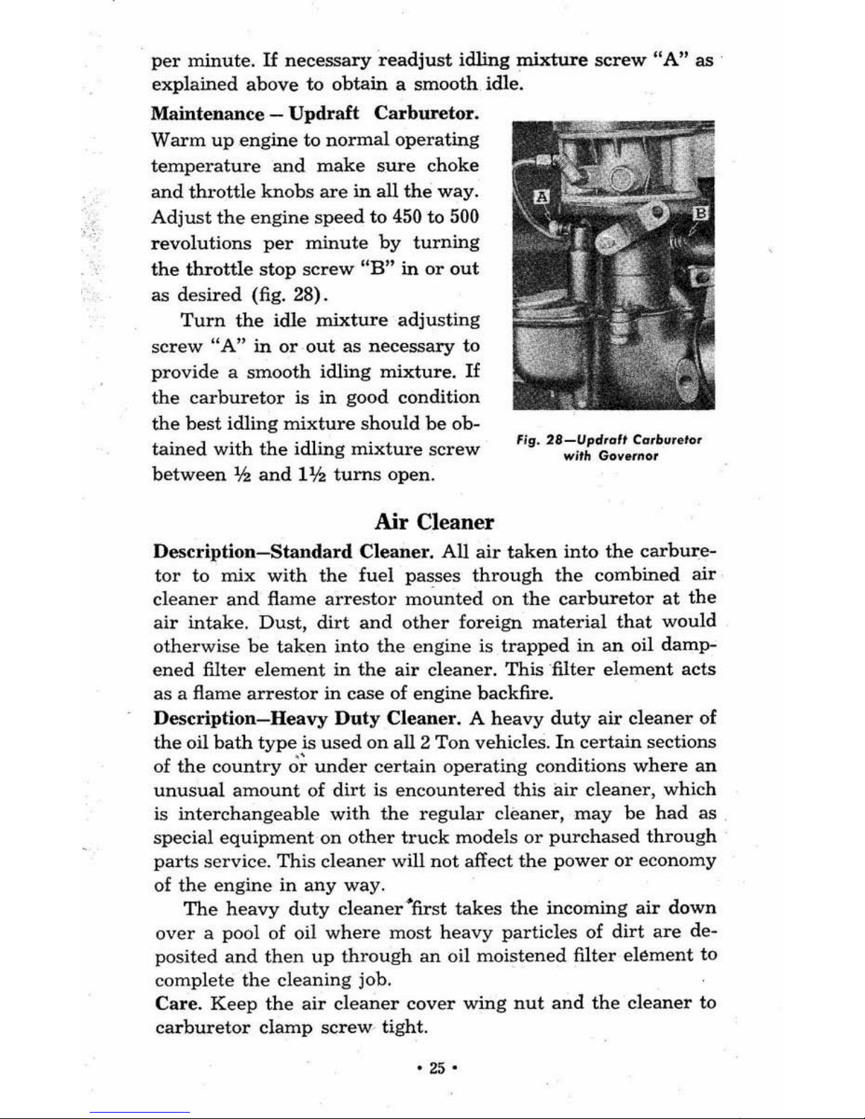
Maintenance -Updraft
Carburetor.
Warm
up
engine
to
normal
operating
temperature
and
make
sure
choke
and
throttle
knobs
are
in
aU
the
way.
Adjust
the
engine
speed
to
450 to 500
revolutions
per
minute
by
turning
the
throttle
stop
screw
"B"
in
or
out
as
desired
(fig. 28).
Turn
the
idle
mixture
adjusting
screw
"A"
in
or
out
as
necessary
to
provide a smooth
idling
mixture.
If
the
carburetor
is
in
good
condition
the
best
idling
mixture
should
be
ob-
tained
with
the
idling
mixture
screw
between
lh
and
Ilh
turns
open.
Air Cleaner
Fig.
28-Upd"./t
Ca,bIJ,eto,
wit" Gover/lot
Description-Standard
Cl
eaner.
AU
air
taken
into
the
carbure-
tor
to
mix
with
the
fuel
passes
through
the
combined
air
cleaner
and
flame
arrestor
mo·
unted
on
the
carburetor
at
the
air
intake.
Dust,
dirt
and
other
foreign
material
that
would
otherwise
be
taken
into
the
engine
is
trapped
in
an
oil
damp-
ened
filter
element
in
the
air
cleaner.
This
'filter
element
acts
as
a flame
arrestor
in
case
of
engine
backfire.
Description-Heavy
Duty
Cleaner. A heavy
duty
air
cleaner
of
the
oil
bath
type
is
used
on
all 2
Ton
vehicles.
In
certain
sections
of
the
country
o~
under
certain
operating
conditions
where
an
unusual
amount
of
dirt
is
encountered
this
air
cleaner,
which
is
interchangeable
with
the
regular
cleaner,
may
be
had
as
special
equipment
on
other
truck
models
or
purchased
through
parts
service.
This
cleaner
will
not
affect
the
power
or
economy
of
the
engine
in
any
way
.
The
heavy
duty
cleaner
"first
takes
the
incoming
air
down
over
a pool
of
oil
where
most
heavy
particles
of
dirt
are
de-
posited
and
then
up
through
an
oil
moistened
filter
element
to
complete
the
cleaning
job.
Care.
Keep
the
air
cleaner
cover
wing
nut
and
the
cleaner
to
carburetor
clamp
screw
tight.
-25
"
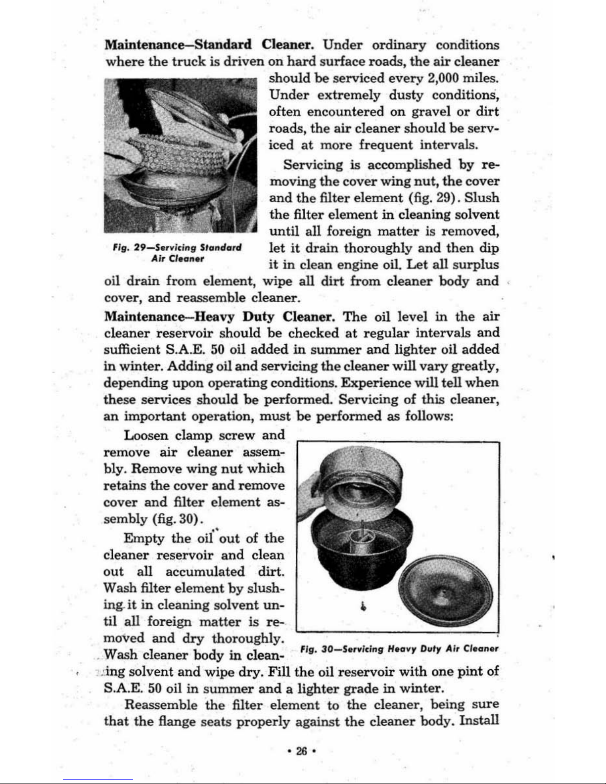
Maintenance-Standard
Cleaner.
Under
ordinary
conditions
where
the
tru
ck
is
driven
on
hard surface
roads,
the
air
cleaner
should
be
serviced
every
2,000 miles.
Under
extremely
dusty
conditions,
often encountered on gravel
or
dirt
roads,
the
air
cleaner
should
be
serv
-
iced
at
more frequent
intervals.
Servicing
is accomplished
by
re-
moving
the
cover
wing
nut,
the
cover
and
the
filter
element
(fig. 29). Sl
ush
the
filter
element
in
cleaning sol
vent
until
all foreign
matter
is removed,
fig. 29_Se,wld"g
Sto"dcm
'
let
it
drain thoroughly
and then
dip
AI,
CI.o".,
it
in
clean engine oil.
Let
all
surplus
oil
drain
from
element, wipe all
dirt
from
cleaner
body
and
'
cove
r,
and
reassemble cleaner.
Maintenance-Heavy
Duty
Cleaner,
The
oil level in
the
air
cleaner
reservoir
should
be
checked
at
regular
intervals
and
sufficient S.A.E.
50
oil
added
in
summer
and
lighter
oil
added
in
winter. Adding oil
and
servicing
the
cleaner
will
vary
greatly,
depending
upon
operating
conditions.
Experience
will tell
when
these
services should
be
performed.
Servicing
of
this cleaner,
an
important
operation,
must
be
performed
as
follows:
Loosen clamp screw
and
remove
air
cleaner
assem-
bly. Remove wing
nut
which
retains
the
cover
and
remove
cover
and
filter
element
as-
sem
bly (fig. 30).
Empty
the
oil"
out
of
the
cleaner
reservoir
and
clean
out
all
accumulated
dirt.
Wash filter el
ement
by
slush-
ing
.
it
in
cleaning solvent
un-
til all foreign
matter
is
re-
moved
and
dry
thoroughly.
'-------=
==---J
. W
ash
cleaner
body
in
clean-
~
15I.
30-$e,wld"s
Hecr
wr O
lltr
Air
CI.o".
,
.'
lng
solvent
and
wipe
dry.
Fill
the
oil
reservoir
with
one
pint
of
S.A.E.
50
oil
in
sununer
and a lighter
grade
in
winter.
Reassemble
the
filter
element
to
the
cleaner, being
sure
that
the
flang e
seats
properly
against
the
cleaner
body. Install
·
26·
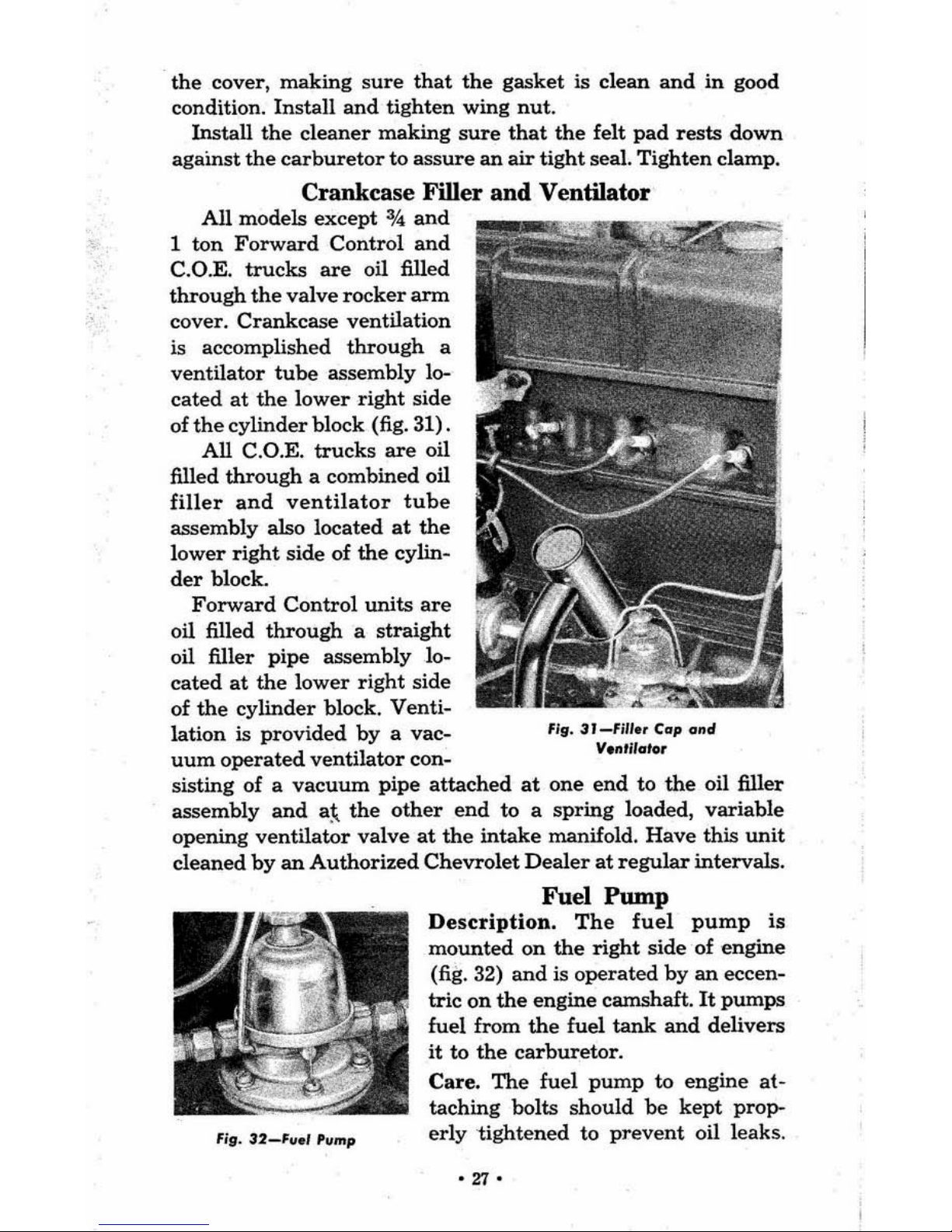
the
cover,
making
sure
that
the
gasket
is
clean
and
in
good
condition.
Install
and
tighten
wing
nut
.
Install
the
cleaner
making
sure
that
the
felt
pad
rests
down
against
the
carburetor
to as
sure
an
air
tight
seal.
Tighten
clamp.
Crankcase Filler and Ventilator
All
models
except
0/4
and
1
ton
Forward
Control
and
C.O.E.
trucks
are
oU
filled
through
the
valve
rocker
ann
cover.
Crankcase
ventilation
is accomplished
through
a
ventilator
tube
assembly
lo-
cated
at
the
lower
right
side
of
the
cylinder
block
(fig. 31).
All
C.O.E.
trucks
are
oil
filled
through a combined
oil
filler
and
ventilator
tube
assembly
also
located
at
the
lower
right
side
of
the
cylin-
der
block.
Forward
Control
units
are
oil filled
through
a
straight
oil filler
pipe
assembly
lo-
cated
at
the
lower
right
side
of
the
cylinder
block.
Venti-
lation
is
provided
by a vac-
uum
operated
ventilator
con-
flg.3T_fm.,C
..
pa"d
V."ril
.. to,
sisting
of a vacuum
pipe
attached
at
one
end
to
the
oil filler
assembly
and
a~
the
other
end
to a
spring
loaded, variable
opening
ventilator
valve
at the
intake
manifold.
Have
this
unit
cleaned
by
an
Authorized
Chevrolet
Dealer
at
regular
intervals.
fig.
32-F".""mp
Fuel
Pump
Description.
The
fuel
pump
is
mounted
on
the
right
side
of
engine
(fig. 32)
and
is
operated
by
an
eceen-
tric
on
the
engine
camshaft.
It
pumps
fuel from
the
fuel
tank
and
delivers
it
to
the
carburetor.
Care. The
fuel
pump
to
engine
at-
taching
bolts
should
be
kept
prop-
erly
'tightened
to
prevent
oil
leaks
.
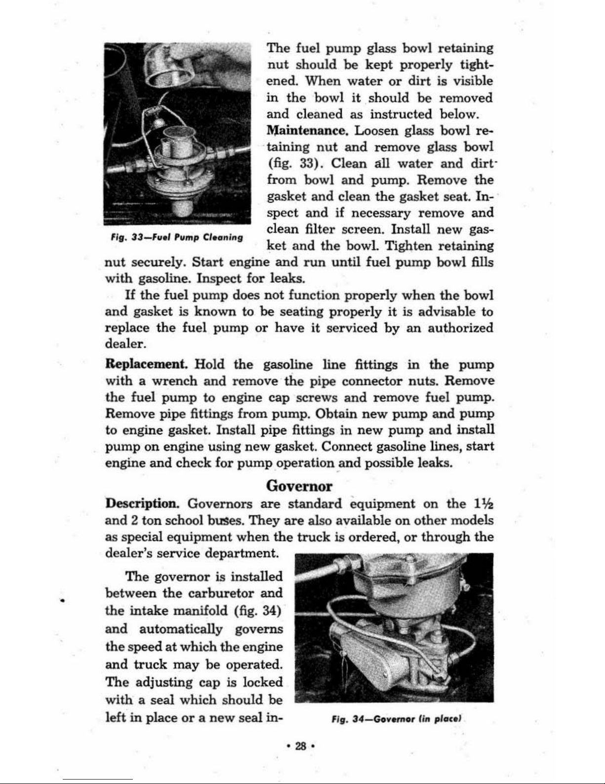
The
fuel
pum
p glass bowl
retaining
nut
should
be
kept
properly
tight-
ened.
When
water
or
dirt
is visible
in
the
bowl
it should
be
removed
and
cleaned
as
instructed
below.
~intenance
.
Loosen glass
bowl re-
taining
nut
and
remove
glass bowl
(fig. 33). Cl
ean
all
water
and
dirt-
fr
om
bowl
and
pump. Remove
the
gasket
and
clean
the
gasket
sea
t.
In-
spec t
and
if
necessary
remove
and
"fI
.
33-',,01
'ump
Clo.n
lnfl
~l:t~n~lt~e
s=:r
T~
~tt:l!
~;:i!:
nut
securely.
Start
engine
and
run
until fu el
pump
bowl fills
with
gasoline.
Inspect
for leaks.
If
the
fuel
pum
p does not function properly
when
the
bowl
and
gasket
is
kn
own
to
be
seating
properly
it
is advisable to
r
ep
lace
the fuel
pump
or
have
it serviced
by
an authorized
dealer.
Replacement. Hold
the
gasoline
line
fittings
in
the pump
with a
wrench and
remove
the
pipe
connector
nuts.
Remove
the
fuel
pump
to engine
cap
screws
and
remove
fuel pump.
Remove
pipe
fittings
from
pump.
Obtain
new
pump
and
pump
to engi
ne
gasket.
Install
pipe fittings in
new
pump
and
install
pump
on engine using
new
gasket.
Connect
gasoline lines,
sta
rt
engine
and
check
for
pump
operation .and
possible leaks.
Governor
Description.
Governors
are
standard
equipment on
the
Ilh
and
2 ton school buses.
They
are
also available
on
other
models
as special
equipment when
the
truc
k is o
rdered, or
through
the
dealer's service
depart
ment.
The
governor
is installed
between
the
car
buretor
and
the
intake
manifold (fig. 34)
and automatically
governs
the speed
at
which
the
engine
and
truck
may
be operated.
The
adjusting cap is locked
with a seal
which
shou
ld
be
left
in
place
or a new
seal in-
",. 34_Gow.,.,.,lin
plln
o'
-,.-
 Loading...