

Page 1
2002 Chevrolet Avalanche
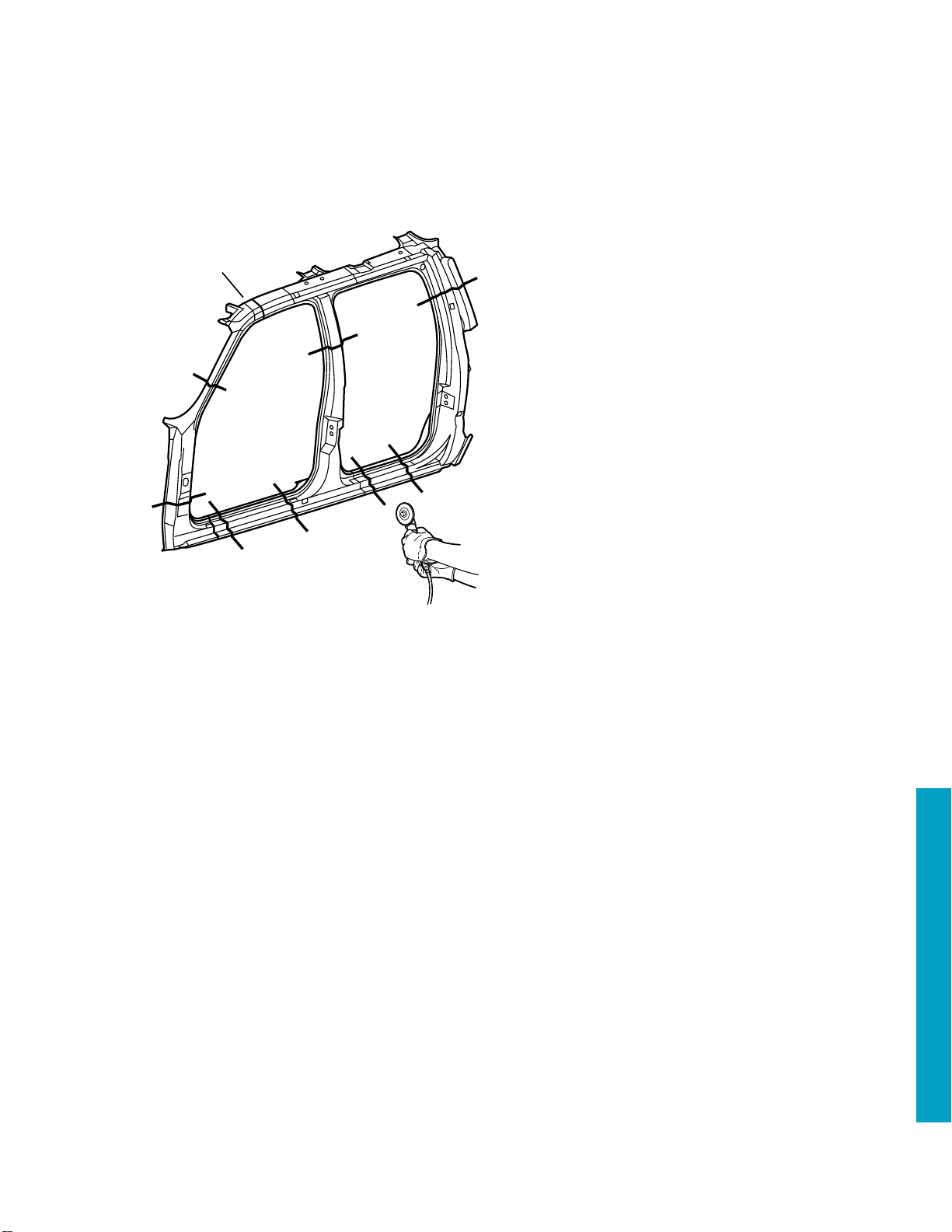
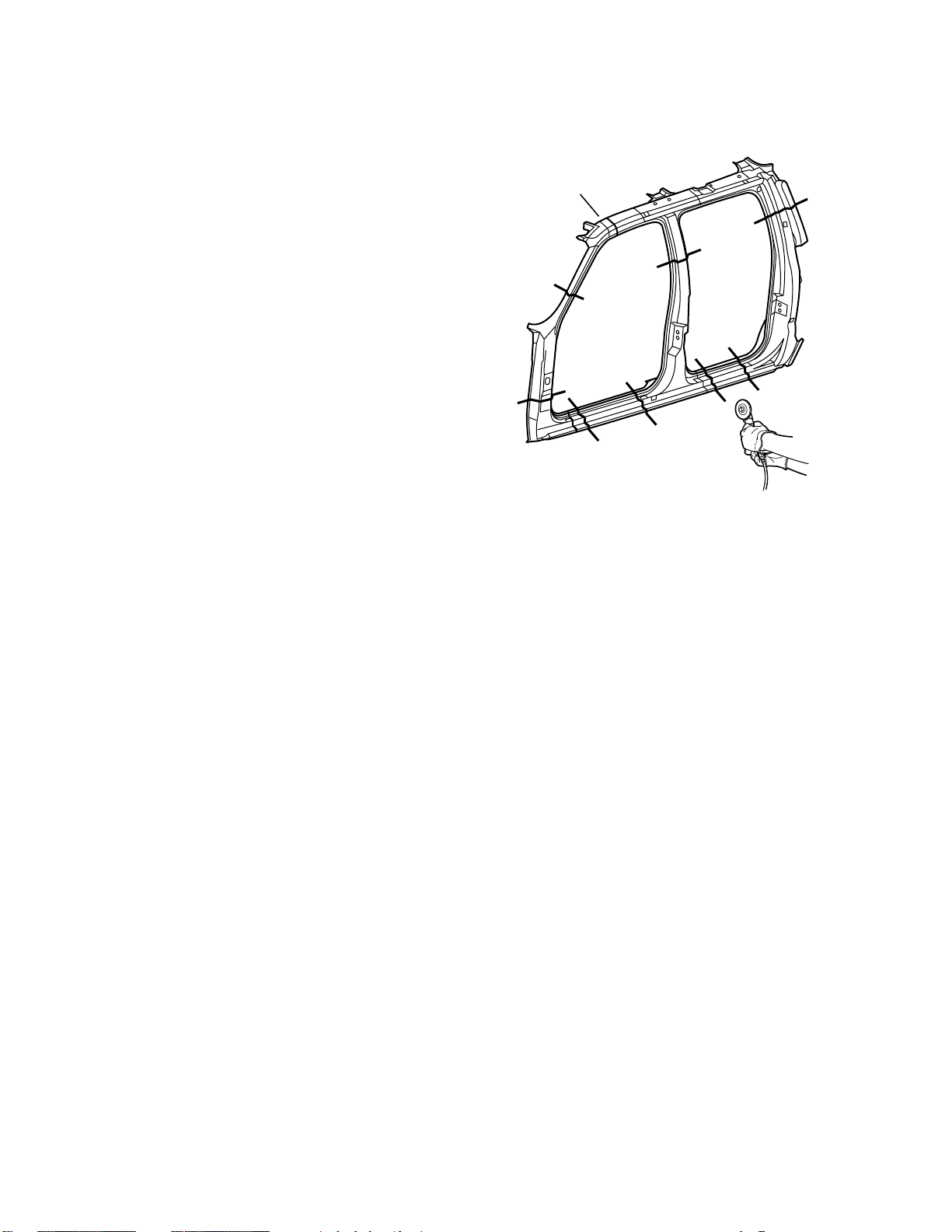
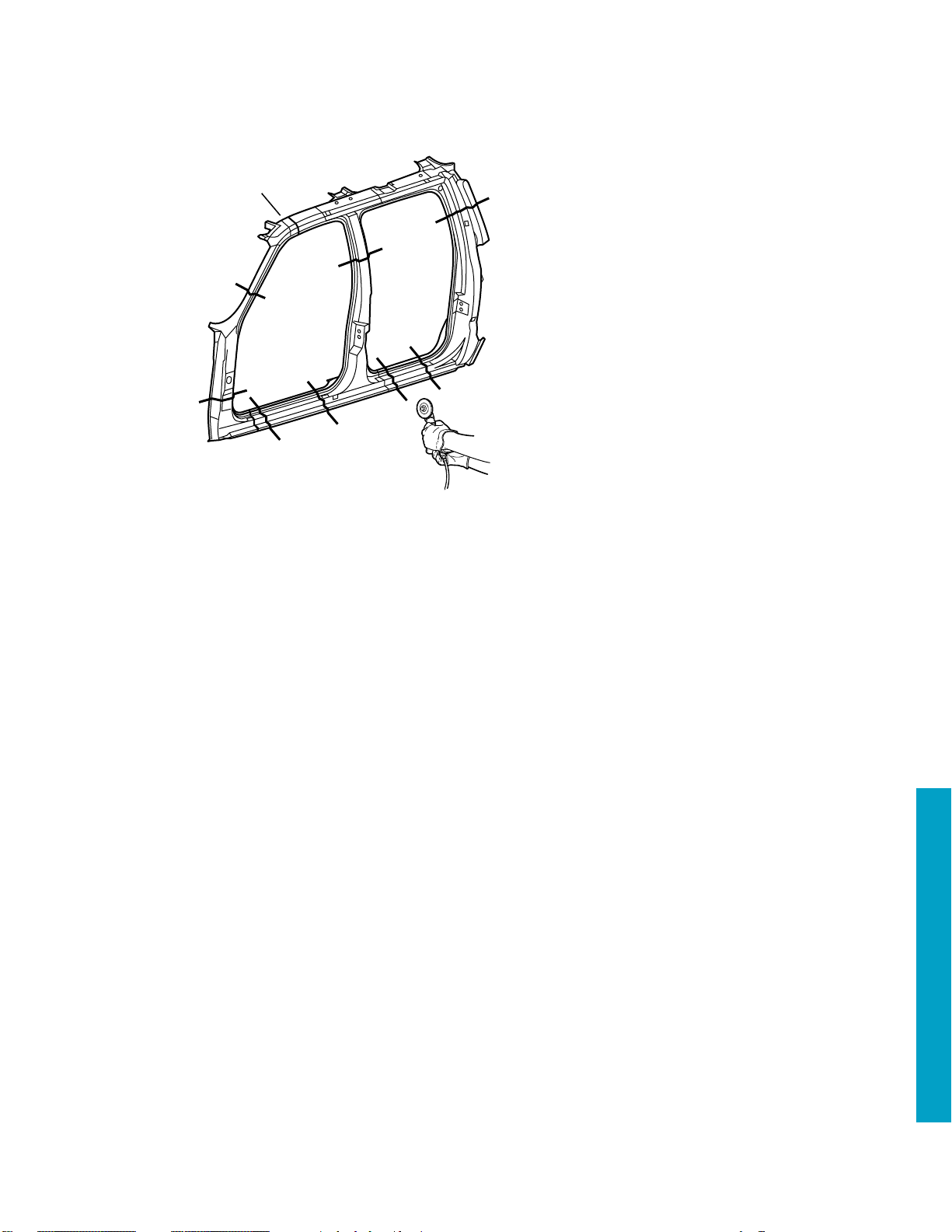
Door Frame
Sectioning
IMPORTANT: Section in specified areas
1
only. Sectioning outside of these areas
may compromise the structural integrity
of the vehicle. Do not section in laser
weld (1) areas of door frame sections.
The door frame opening is a unique
laser-weld design incorporating multiple
metal thicknesses to ensure the
structural integrity of the cab. The door
frame can be replaced at factory seams,
but requires the removal of the roof
panel, windshield and quarter panel.
Sectioning procedures have been
developed as a more cost-effective
alternative to complete replacement. The
specific area to be sectioned is
determined by the extent of the damage
to the vehicle.
2002 Avalanche 3-1
2002 Chevrolet Avalanche
Page 2
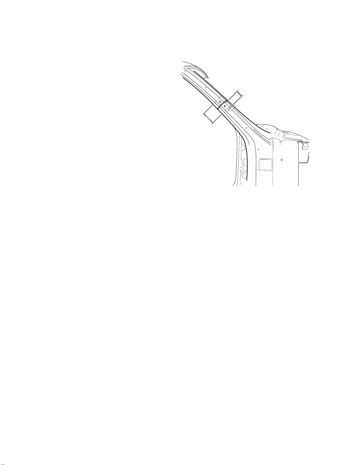
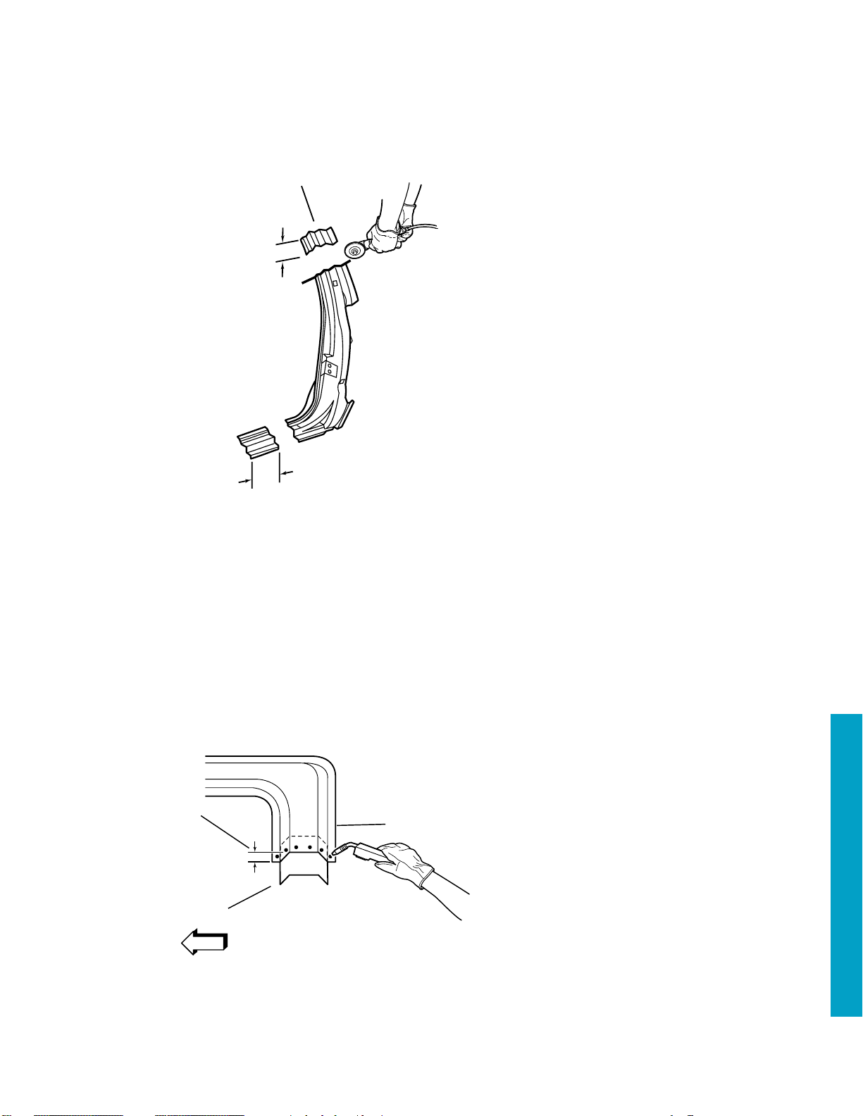
Windshield Pillar
Sectioning
Removal Procedure
1. Remove all related panels and
components.
2. Restore as much of the damage as
possible to factory specifications.
3. Note the location and remove the
following as necessary:
• Sealers
• Sound deadeners
• Anti-corrosion materials
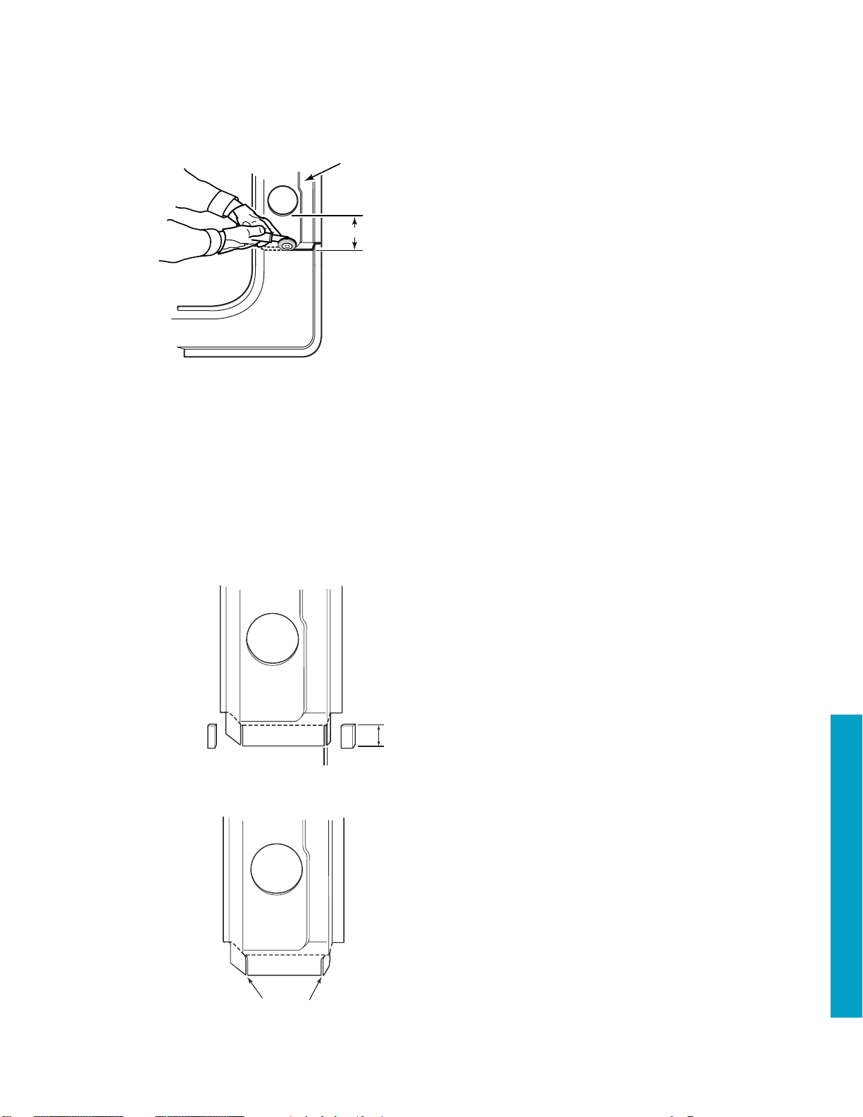
IMPORTANT: Perform sectioning
in the windshield area 30␣ mm
(1-3/16␣ in.) above the third trim
mounting hole.
IMPORTANT: Take care not to
damage the inner panels or
reinforcements.
4. Cut the pillar in the locations where
sectioning is to be performed.
5. Locate and drill out all factory
welds. Note the number and
location of the welds for installation
of the service part.
6. Remove the damaged Windshield
Pillar section.
30 MM (1-3/16 IN)
50 MM (2 IN)
3-2 2002 Avalanche
Page 3
50 MM
(2 IN)
100 MM
(4 IN)
100MM
(4 IN)
BACKING PLATE
GAP = ONE AND ONE-HALF TIMES
THE THICKNESS OF THE METAL
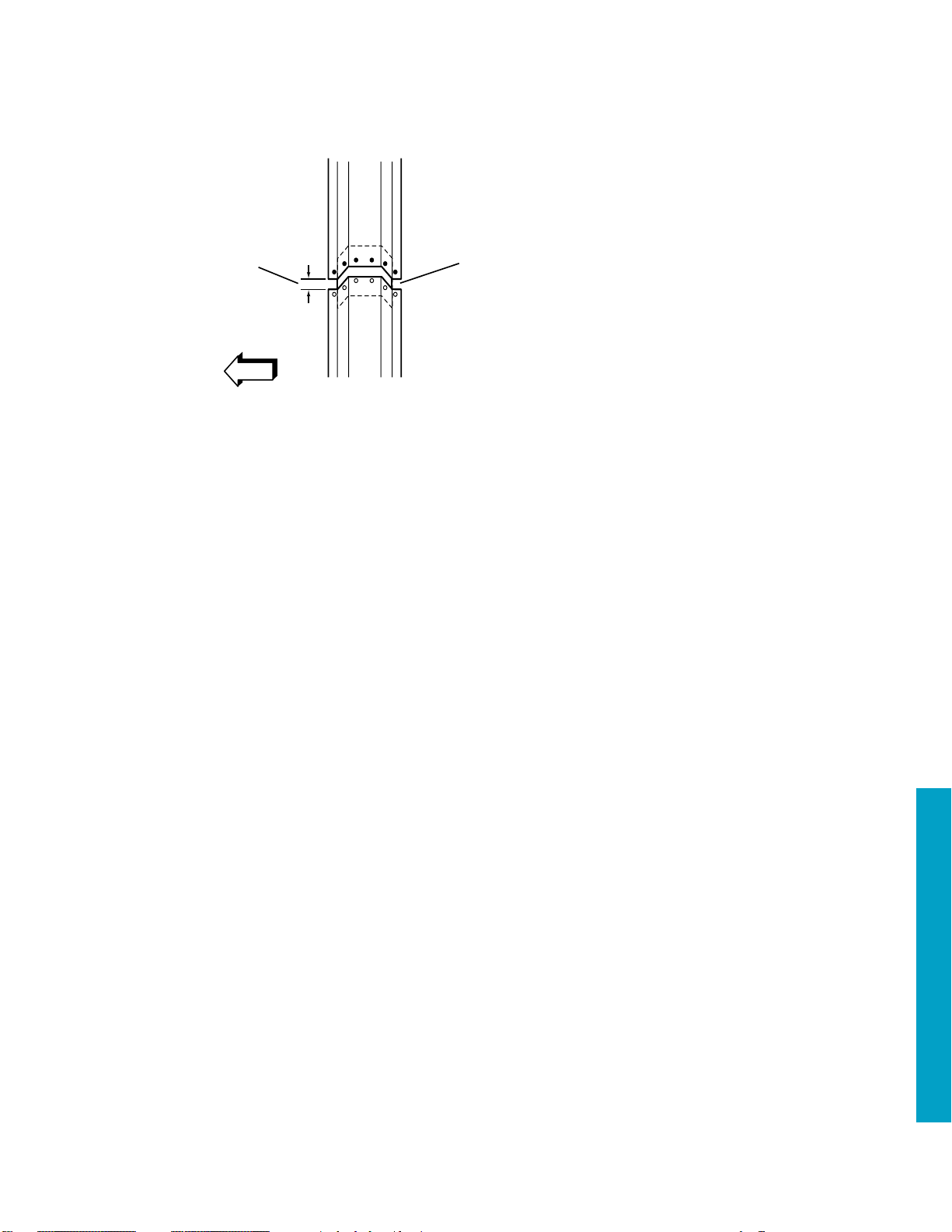
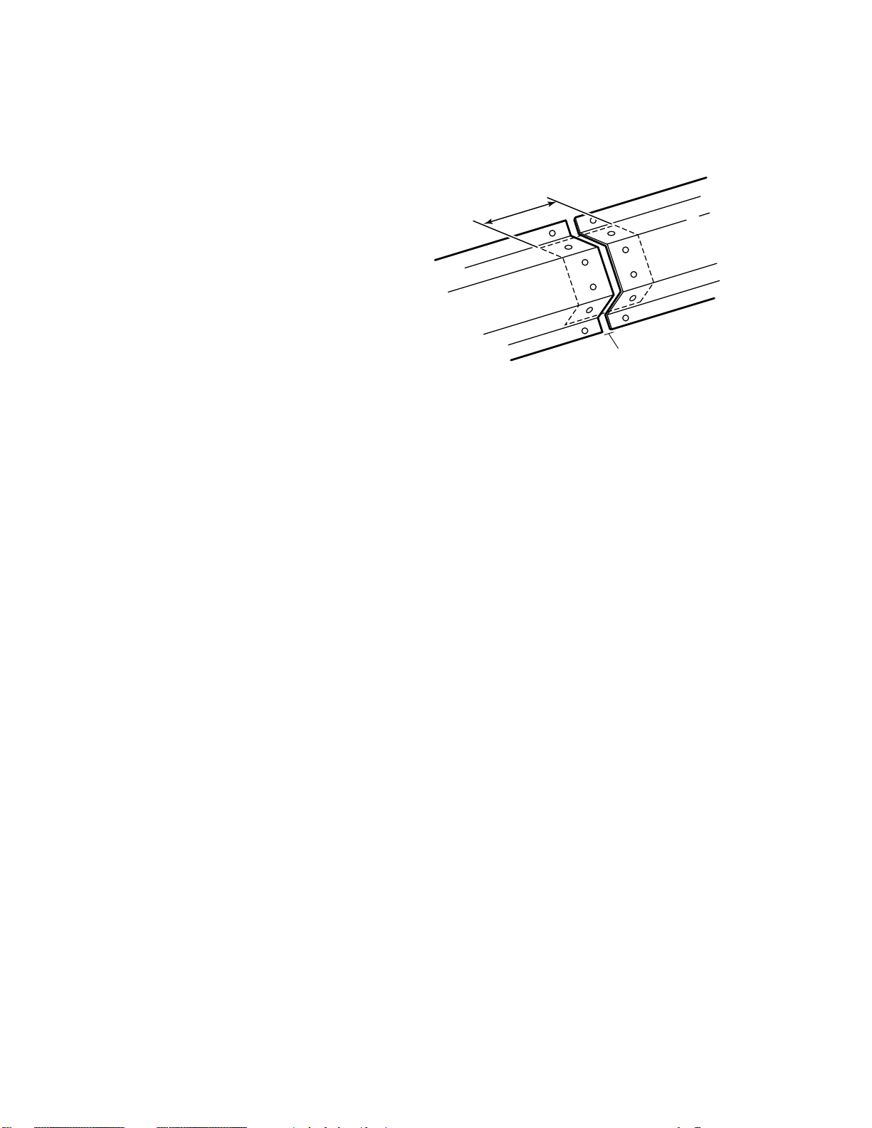
Windshield Pillar
Sectioning
Installation Procedure
1. Cut the replacement pillar in
corresponding locations to fit the
remaining original panel. The
sectioning joint should be trimmed
to allow a gap of one and one-half
times the metal thickness at the
sectioning joint.
2. Create a 50␣ mm (2␣ in.) backing
plate from the unused portion of the
service part. Trim the backing plate
as necessary to fit behind the
sectioning joint.
3. Perform additional sectioning
procedures as necessary. Refer to
Center Pillar Sectioning; Front
Lower Pillar Sectioning; Rear Lock
Pillar Sectioning; and Rocker
Sectioning.
4. Drill 8␣ mm (5/16␣ in.) holes for plug
welding in the original part. Locate
these holes approximately 13␣ mm
(1/2␣ in.) from the edge of the
sectioning cuts and spaced 40␣ mm
(1-1/2␣ in.) apart.
5. Drill 8␣ mm (5/16␣ in.) plug weld
holes in the service panel as
necessary in the locations noted
from the original panel and along
the sectioning cut.
CAUTION: FOAM SEALERS ARE
FLAMMABLE AND SHOULD BE
REMOVED FROM ALL WELD
LOCATIONS.
6. Prepare the mating surfaces, as
necessary.
7. Apply weld-through primer to all
bare metal surfaces.
PLUG WELDS
13 MM
(1/2 IN)
BACKING PLATE
ORIGINAL PART
8. Fit the backing plate halfway into
the sectioning joint, clamp and plug
weld to the vehicle.
9. Align the Windshield Pillar to
adjacent panels using threedimensional measuring equipment.
10. Plug weld accordingly.
—continued
2002 Avalanche 3-3
Page 4
Windshield Pillar Sectioning
Installation Procedure con’t
11. Make 25␣ mm (1␣ in.) stitch welds
along the seam with 25␣ mm (1␣ in.)
gaps between them, then go back
and complete the stitch weld. This
will create a solid joint with minimal
heat distortion.
12. Clean and prepare all welded
surfaces.
IMPORTANT: Prior to refinishing,
refer to the publication GM4901MD-01 GM Approved Refinish
Materials for recommended
products. Do not combine paint
systems. Refer to paint
manufacturer’s recommendations.
13. Apply an approved anti-corrosion
primer.
14. Apply sealers and refinish as
necessary.
15. Install all related panels and
components.
GAP =
ONE AND ONE-HALF TIMES
MET AL THICKNESS
STITCH WELD
3-4 2002 Avalanche
Page 5
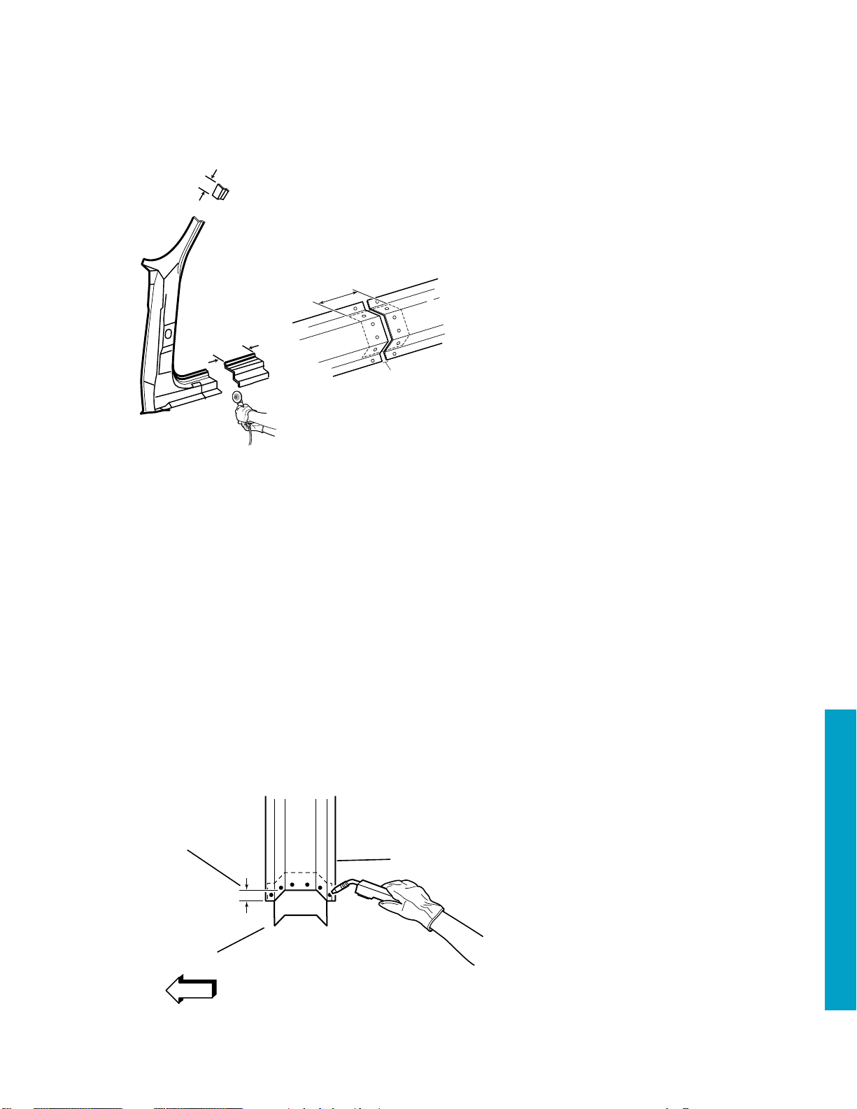
Front Lower Hinge
Pillar Sectioning
ORIGINAL
PANEL
80 MM (3-1/8 IN)
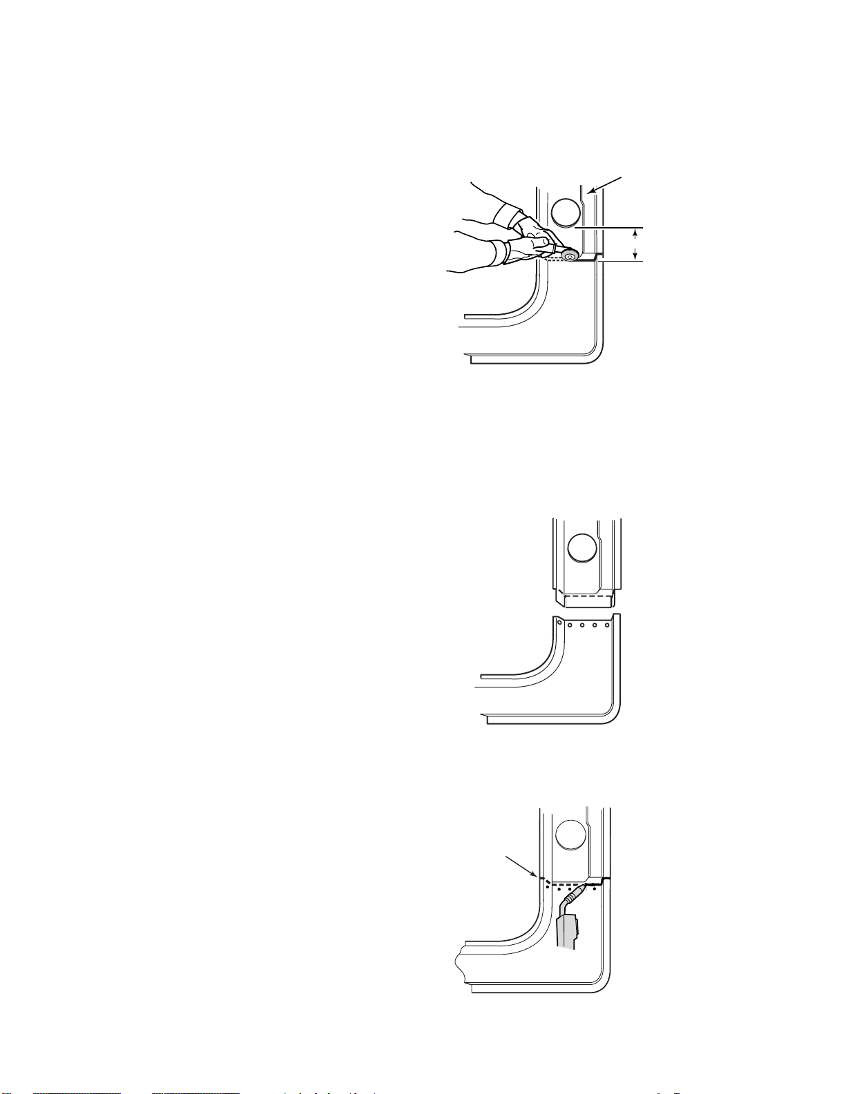
Removal Procedure
1. Visually inspect and restore as much of
the damage as possible to factory
specifications.
2. Remove all related panels and
components.
3. Note the location and remove the
following as necessary:
• Sealers
• Sound deadeners
• Anti-corrosion materials
4. Measure 80␣ mm (3-1/8 inches) down
from the large wiring harness hole in the
hinge pillar and mark a horizontal line.
5. Cut the pillar in the locations where
sectioning is to be performed.
IMPORTANT: Take care not to damage
the inner panel.
6. Locate, mark and drill out all necessary
factory welds. Note the number of welds
for the installation of the service section.
7. Remove the damaged section of the door
frame opening.
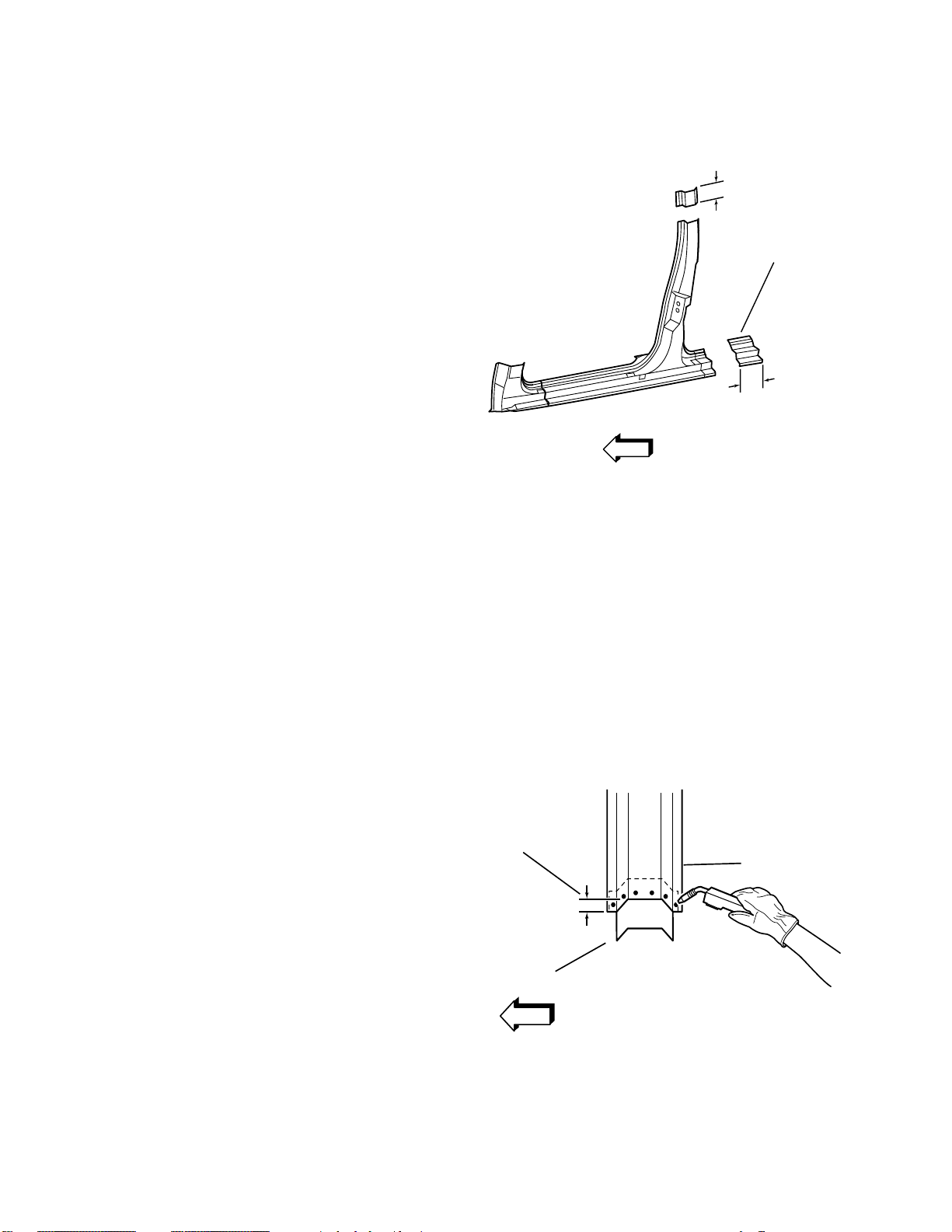
5 MM (3/16 IN)
IMPORTANT: The metal of the hinge
pillar is of a heavy gauge. However, the
tabs can be created using the appropriate
tools.
8. Cut and remove 30␣ mm (1-3/16 inches)
from the flanges on either side of the
remaining section of the original hinge
pillar to create 30␣ mm (1-3/16␣ in.) tabs.
Cut 5␣ mm (3/16␣ in.) wide gaps in the
bottom corners.
30 MM (1-3/16 IN)
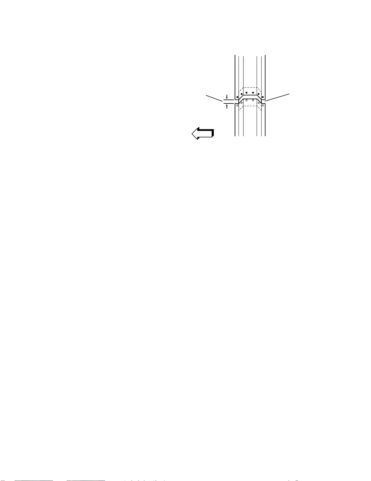
9. Step the tabs inward to allow the door
frame opening service section to fit over
the original hinge pillar. Weld the tabs
together along the edges.
WELD TOGETHER
2002 Avalanche 3-5
Page 6
Front Lower Hinge
Pillar Sectioning
Installation Procedure
1. On the service part, measure 50␣ mm (2␣ in.)
down from the large wiring harness hole in
the hinge pillar and mark a horizontal line.
Cut the hinge pillar along this line.
2. Perform additional sectioning procedures as
necessary to remove the unused areas of
the service part. Refer to Windshield
Sectioning; Center Pillar, Rear Lock Pillar,
and Rocker Sectioning.
NOTICE: In any area damaged beyond
recognition, space plug weld holes every
40␣ mm (1-1/2␣ in.) apart.
3. Drill 8␣ mm (5/16␣ in.) plug weld holes as
necessary in the locations noted from the
original section. Also drill plug weld holes
along the hinge pillar sectioning cut of the
service part. These should be located
approximately 15␣ mm (9/16␣ in.) from the
edge of the cut.
CAUTION: FOAM SEALERS ARE
FLAMMABLE AND SHOULD BE
REMOVED FROM ALL WELD
LOCATIONS.
4. Prepare mating surfaces as necessary.
5. Apply weld-thru primer to all bare-metal
surfaces.
SERVICE
PANEL
50 MM (2 IN)
ORIGINAL
PANEL
6. Position the service section over the
stepped tab on the original hinge pillar,
allowing 30␣ mm (1-3/16 inches) of overlap.
Check fit using three-dimensional
measuring.
7. Plug weld service part in position.
8. Make 25␣ mm (1␣ in.) welds along the seam
with 25␣ mm (1␣ in.) gaps between. Then go
back and complete the stitch weld. This
will create a solid joint with minimal heat
distortion.
9. Clean and prepare all welded surfaces.
IMPORTANT: Prior to refinishing,
refer to the publication GM4901M-D-01
GM Approved Refinish Materials for
recommended products. Do not combine
paint systems. Refer to paint manufacturer’s
recommendations.
10. Apply an approved anti-corrosion primer.
11. Apply sealers and refinish as necessary.
12. Install all related panels and components.
30 MM (1-3/16 IN)
OF OVERLAP
NEW
SERVICE PANEL
ORIGINAL
PANEL
3-6 2002 Avalanche
Page 7
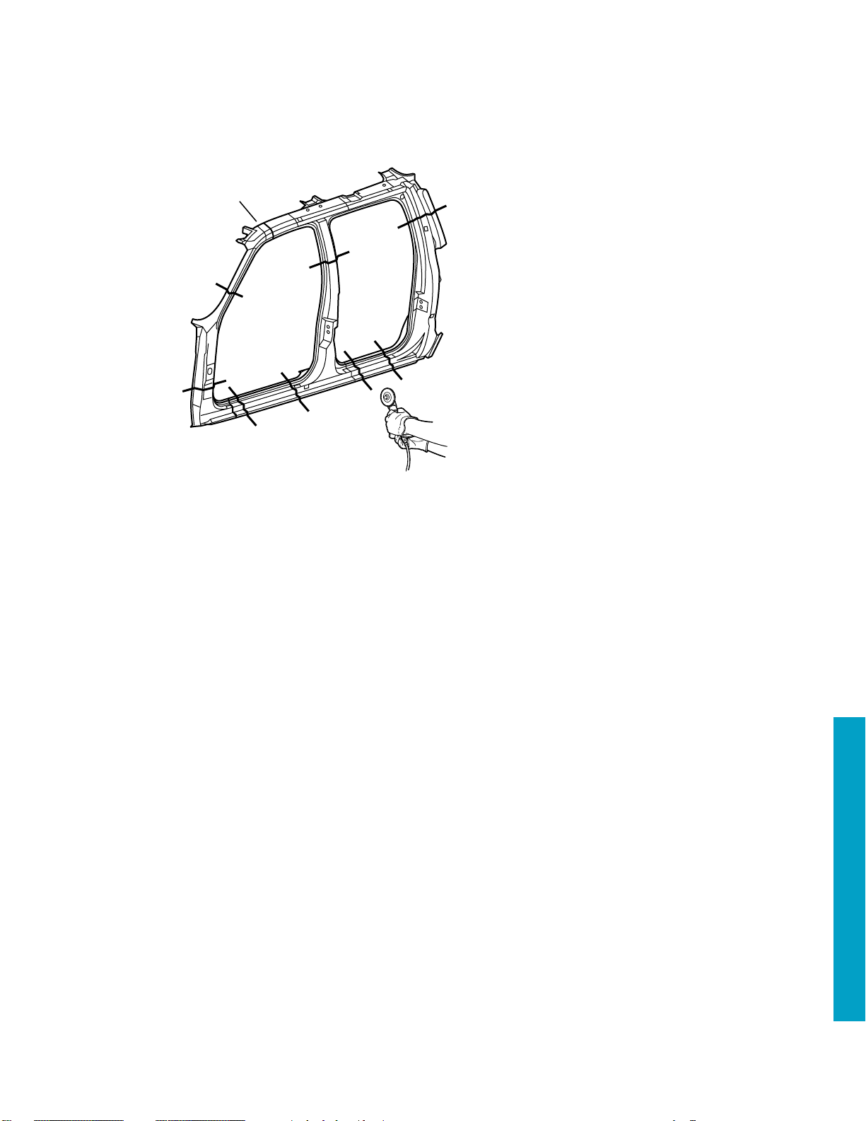
Center Pillar
Sectioning
Removal Procedure
1. Remove all related panels and
1
components.
2. Restore as much of the damage as
possible to factory specifications.
3. Note the location and remove the
following as necessary:
• Sealers
• Sound deadeners
• Anti-corrosion materials
IMPORTANT: Take care not to
damage the inner panels or
reinforcements.
4. Cut the Center Pillar in the location
where sectioning is to be performed.
5. Locate and drill out all factory
welds. Note the number and
location of the welds for installation
of the service part.
6. Remove the damaged Center Pillar
section.
2002 Avalanche 3-7
Page 8
Center Pillar
Sectioning
Installation Procedure
1. Cut the replacement Center Pillar in
corresponding locations to fit the
remaining original panel. The sectioning
joint should be trimmed to allow a gap of
one-and-one-half times the metal
thickness at the sectioning joint.
2. Create a 50␣ mm (2␣ in.) backing plate
from the unused portion of the service
part. Trim the backing plate as necessary
to fit behind the sectioning joint.
3. Perform additional sectioning procedures
as necessary. Refer to Windshield
Sectioning; Front Lower Pillar
Sectioning; Rear Lock Pillar Sectioning;
and Rocker Sectioning.
4. Drill 8␣ mm (5/16␣ in.) plug weld holes
along the sectioning cut on the
remaining original part.
5. Drill 8␣ mm (5/16␣ in.) plug weld holes in
the service panel as necessary in the
locations noted from the original panel
and along the sectioning cut.
CAUTION: FOAM SEALERS ARE
FLA␣ MMABLE AND SHOULD BE
REMOVED FROM ALL WELD
LOCATIONS.
6. Prepare the mating surfaces as necessary.
7. Apply weld-through primer to all bare
metal surfaces.
50MM
(2 IN)
1
100MM
(4 IN)
8. Fit the backing plate halfway into the
sectioning joint, clamp and plug weld to
the vehicle.
—continued
3-8 2002 Avalanche
PLUG WELDS
ORIGINAL PART
13 MM
(1/2 IN)
BACKING PLATE
Page 9
GAP =
ONE AND ONE-HALF TIMES
MET AL THICKNESS
STITCH WELD
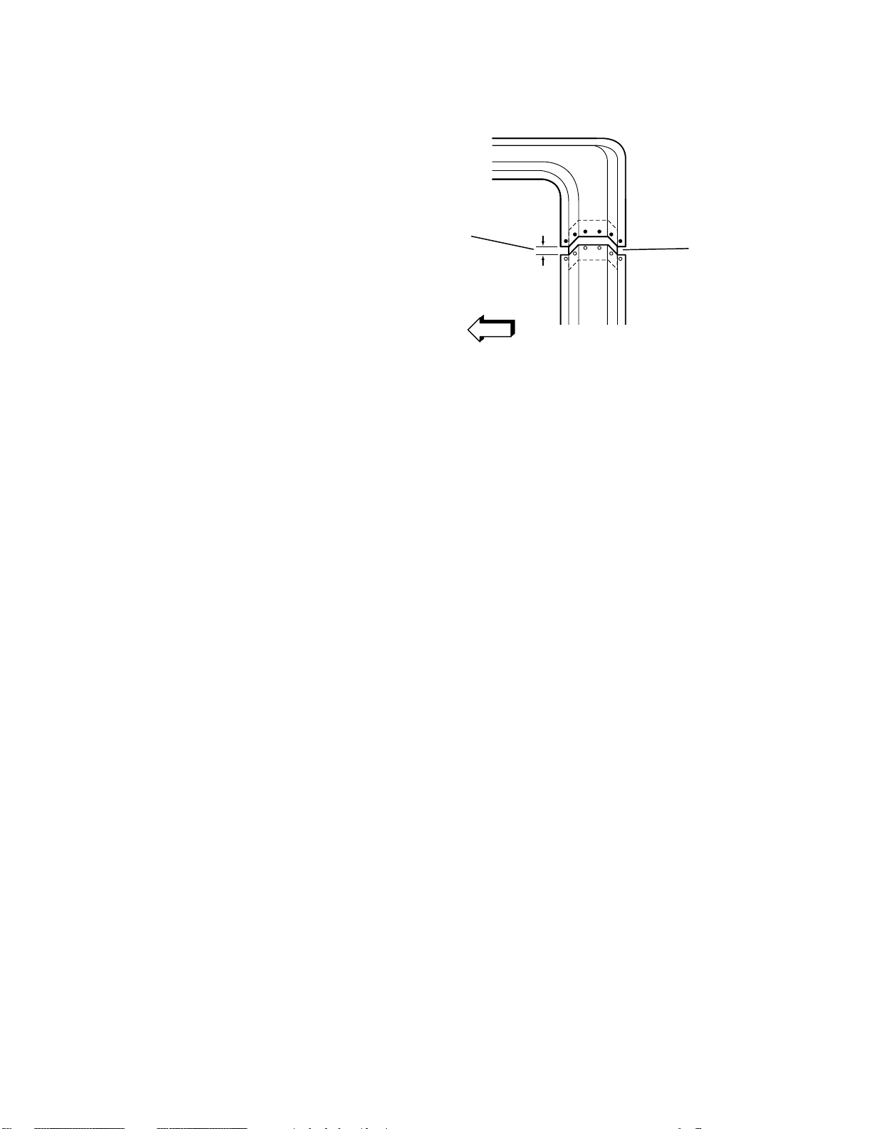
Center Pillar Sectioning
Installation Procedure con’t
9. Align the Center Pillar to adjacent
panels using three-dimensional
measuring equipment.
10. Plug weld accordingly.
11. Make 25␣ mm (1␣ in.) stitch welds
along the seam with 25␣ mm (1␣ in.)
gaps between them, then go back
and complete the stitch weld. This
will create a solid joint with minimal
heat distortion.
12. Clean and prepare all welded
surfaces.
IMPORTANT: Prior to refinishing,
refer to the publication GM4901MD-01 GM Approved Refinish
Materials for recommended
products. Do not combine paint
systems. Refer to paint
manufacturer’s recommendations.
13. Apply an approved anti-corrosion
primer.
14. Apply sealers and refinish as
necessary.
15. Install all related panels and
components.
2002 Avalanche 3-9
Page 10
Rear Lock Pillar
Sectioning
Removal Procedure
1. Remove all related panels and components.
2. Restore as much of the damage as possible to
factory specifications.
3. Note the location and remove the following
as necessary:
• Sealers
• Sound deadeners
• Anti-corrosion materials
IMPORTANT: Take care not to damage the
inner panels or reinforcements.
4. Cut the Rear Lock Pillar in the locations
where sectioning is to be performed.
5. Locate and drill out all factory welds. Note
the number and location of the welds for
installation of the service part.
6. Remove the damaged Rear Lock Pillar
section.
1
3-10 2002 Avalanche
Page 11
BACKING PLATE
50 MM
(2 IN)
100 MM
(4 IN)
Rear Lock Pillar
Sectioning
Installation Procedure
1. Cut the replacement Rear Lock
Pillar in corresponding locations to
fit the remaining original panel. The
sectioning joint should be trimmed
to allow a gap of one-and-one-half
times the metal thickness at the
sectioning joint.
2. Create a 50␣ mm (2␣ in.) backing
plate from the unused portion of the
service part. Trim the backing plate
as necessary to fit behind the
sectioning joint.
3. Perform additional sectioning
procedures as necessary. Refer to
Windshield Sectioning; Front Lower
Pillar Sectioning; Center Pillar; and
Rocker Sectioning.
4. Drill 8 ␣ mm (5/16␣ in.) plug weld
holes along the sectioning cut on
the remaining original part.
5. Drill 8␣ mm (5/16␣ in.) plug weld
holes in the service panel as
necessary in the locations noted
from the original panel and along
the sectioning cut.
CAUTION: FOAM SEALERS ARE
FLAMMABLE AND SHOULD BE
REMOVED FROM ALL WELD
LOCATIONS.
6. Prepare the mating surfaces, as
necessary.
7. Apply weld-through primer to all
bare metal surfaces.
PLUG WELDS
13 MM
(1/2 IN)
BACKING PLATE
8. Fit the backing plate halfway into
the sectioning joint, clamp and plug
weld to the vehicle.
ORIGINAL PANEL
2002 Avalanche 3-11
Page 12
Rear Lock Pillar Sectioning
Installation Procedure con’t
9. Align the Rear Lock Pillar to
adjacent panels using threedimensional measuring equipment.
10. Plug weld accordingly.
11. Make 25␣ mm (1␣ in.) stitch welds
along the seam with 25␣ mm (1␣ in.)
gaps between them, then go back
and complete the stitch weld. This
will create a solid joint with minimal
heat distortion.
12. Clean and prepare all welded
surfaces.
IMPORTANT: Prior to refinishing,
refer to the publication GM4901MD-01 GM Approved Refinish
Materials for recommended
products. Do not combine paint
systems. Refer to paint
manufacturer’s recommendations.
13. Apply an approved anti-corrosion
primer.
14. Apply sealers and refinish as
necessary.
15. Install all related panels and
components.
GAP =
ONE AND ONE-HALF TIMES
THE METAL THICKNESS
STITCH WELD
3-12 2002 Avalanche
Page 13
Rocker Panel
Sectioning
Removal Procedure
1
1. Remove all related panels and
components.
2. Restore as much of the damage as
possible to factory specifications.
3. Note the location and remove the
following as necessary:
• Sealers
• Sound deadeners
• Anti-corrosion materials
IMPORTANT: Take care not to
damage the inner panels or
reinforcements.
4. Cut the Rocker Panel in the
locations where sectioning is to be
performed.
5. Locate and drill out all factory
welds. Note the number and
location of the welds for installation
of the service part.
6. Remove the damaged Rocker Panel
section.
2002 Avalanche 3-13
Page 14
Rocker Panel
Sectioning
Installation Procedure
1. Cut the replacement Rocker Panel in
corresponding locations to fit the
remaining original panel. The sectioning
joint should be trimmed to allow a gap of
one-and-one-half times the metal thickness
at the sectioning joint.
2. Create a 100␣ mm (4␣ in.) backing plate
from the unused portion of the service
part. Trim the backing plate as necessary
to fit behind the sectioning joint.
3. Perform additional sectioning procedures
as necessary. Refer to Windshield
Sectioning; Front Lower Pillar Sectioning;
Rear Lock Pillar Sectioning; and Center
Pillar sectioning.
4. Drill 8␣ mm (5/16␣ in.) plug weld holes along
the sectioning cut on the remaining
original part.
5. Drill 8␣ mm (5/16␣ in.) plug weld holes in
the service panel as necessary in the
locations noted from the original panel and
along the sectioning cut.
CAUTION: FOAM SEALERS ARE
FLAMMABLE AND SHOULD BE
REMOVED FROM ALL WELD
LOCATIONS.
6. Prepare the mating surfaces as necessary.
7. Apply weld-through primer to all bare
metal surfaces.
8. Fit the backing plate halfway into the
sectioning joint, clamp and plug weld to
the vehicle.
9. Align the Rocker Panel to adjacent panels
using three-dimensional measuring
equipment.
10. Plug weld service part in position.
11. Make 25␣ mm (1␣ in.) stitch welds along the
seam with 25␣ mm (1␣ in.) gaps between
them, then go back and complete the
stitch weld. This will create a solid joint
with minimal heat distortion.
12. Clean and prepare all welded surfaces.
IMPORTANT: Prior to refinishing, refer to
the publication GM4901M-D-2000 “GM
Approved Refinish Materials” for
recommended products. Do not combine
paint systems. Refer to paint manufacturer’s
recommendations.
13. Apply an approved anti-corrosion primer.
14. Apply sealers and refinish as necessary.
15. Install all related panels and components.
100 MM
(4 IN)
BACKING PLATE
GAP = ONE AND ONE-HALF TIMES
THE THICKNESS OF THE METAL
3-14 2002 Avalanche
Page 15

Front Body-Side
Hinge Replacement
Removal Procedure
1. Remove related panels and
component.
2. Remove any excess sealer
surrounding the existing hinge and
scribe the location of the hinge on
the hinge pillar.
3. Lightly hand-sand the existing hinge
with 100 grit or finer sandpaper in
order to locate the
4 welds that attach the hinge to the
pillar.
IMPORTANT: Punch the center of
the weld so that as much of the weld
as possible is removed during the
drilling.
4. Center punch each of the four weld
marks on the original hinge.
DRILL THROUGH HINGE ONLY
13 MM (1/2 IN)
ROTABROACH BIT
HINGE
PILLAR
HINGE REINFORCEMENT
TYPICAL MIG WELD
IMPORTANT: Do not drill into the
hinge pillar.
5. Drill through the hinge only, at each
punch location. Use a 13␣ mm (1/
2␣ in.) rotabroach hole saw or
equivalent.
6. Remove the hinge. If necessary, use
a chisel in order to separate the
hinge from the pillar.
7. Remove all of the remaining weld
from the pillar surface in order to
ensure a flush fit of the service
hinge.
2002 Avalanche 3-15
Page 16

Front Body-Side
Hinge Replacement
Installation Procedure
1. Repair any damage done to the pillar
during the drilling or the removal.
2. Position the service hinge within the
scribe marks on the pillar.
3. Center punch each stud location on
the hinge pillar according to the
service hinge.
4. Drill a 3 ␣ mm (1/8␣ in.) pilot hole at
each center punch location.
IMPORTANT: Drill must be exact size.
5. Drill an 11.5 mm (29/64␣ in.) hole at
the pilot locations for the studs.
IMPORTANT: Prior to refinishing,
refer to the publication GM4901M-D2000 “GM Approved Refinish
Materials” for recommended products.
Do not combine paint systems. Refer to
paint manufacturer’s
recommendations.
6. Clean and prepare all of the bare
metal surfaces.
7. Apply an approved anti-corrosion
primer.
3 MM (1/8 IN)
PILOT
11.5 MM (29/64 IN)
DRILL
8. Feed fish wire, GM P/N 15017229 or
the equivalent, through the hinge, the
hinge stud hole and out of the
conduit hole in the pillar.
9. Install the stud, GM P/N 15017230,
supplied with the service hinge into
the wire end. Pull the stud into
position.
10. Hold the stud in position with the
hinge and remove the fish wire.
11. Draw the stud tight through the
pillar. Use the nuts (GM P/N
11516746) supplied.
12. Repeat steps 7-10 on the remaining
stud locations.
13. Remove each service nut.
14. Apply a full-bodied caulk to the entire
hinge mounting surface in order to
ensure a proper seal.
3-16 2002 Avalanche
Page 17

Hinge
Nuts
Pillar
Hinge
Reinforcement
Studs
Front Body-Side Hinge
Replacement
Installation Procedure con’t
15. Install the hinge to the pillar. Use
the supplied nuts.
16. Torque the hinge to the pillar nuts
to 25␣ ␣ N·m (18 ft lb.).
17. Clean and prepare all of the
surfaces as necessary for refinishing.
18. Apply the sealers. Refinish the
surfaces as necessary.
19. Install and align all of the related
panels and the components.
2002 Avalanche 3-17
Page 18

Front Door-Side
13mm (1/2 inch)
Rotabroach Bit
Hinge
Door
Hinge Reinforcement
Typical Mig Weld
Drill through hinge only
Hinge Replacement
Removal Procedure
1. Remove related panels and
components.
2. Remove any excess sealer surrounding
the hinge and scribe the location of
the hinge on the door.
3. Lightly hand-sand the existing body
hinge with 100 grit or finer sandpaper
in order to locate the 4 welds that
attach the hinge to the door.
IMPORTANT: Punch the center of the
weld so that as much of the weld is
removed during the drilling as possible.
4. Center punch each of the four weld
marks on the original hinge base.
IMPORTANT: Do not drill into the
door.
5. Drill through hinge base only at the
punch location. Use a 13 mm (1/2␣ in.)
rotabroach hole saw, or the equivalent.
6. Remove hinge. If necessary, use a
chisel to separate the hinge from the
door.
7. Remove all of the remaining weld from
the door surface in order to ensure a
flush fit of the service hinge.
3-18 2002 Avalanche
Page 19

3 MM (1/8 IN)
PILOT
13 MM (1/2 IN)
DRILL
Front Door-Side
Hinge Replacement
Installation Procedure
1. Repair any damage done to door
during the drilling or the removal.
2. Clean and prepare the backing plate
mounting surfaces in order to
ensure a flush fit of the backing
plate.
3. Position the service hinge within the
scribe marks on the door.
4. Center punch each hole location on
the door according to the service
hinge.
5. Drill a 3 mm (1/8␣ in.) pilot hole at
each center punch location.
6. Drill a 13 mm (1/2␣ in.) hole at the
pilot locations.
IMPORTANT: Prior to refinishing,
refer to the publication GM4901MD-2000 “GM Approved Refinish
Materials” for recommended
products. Do not combine paint
systems. Refer to paint
manufacturer’s recommendations.
7. Clean and prepare all of the bare
metal surfaces.
8. Apply an approved anti-corrosion
primer.
9. Apply full-bodied caulk to the entire
hinge mounting surface in order to
ensure a proper seal.
HINGE
DOOR
BOLTS
BACKING
PLATE
10. Align the hinge and the backing
plate with the holes in the door
(Fig. 4-34).
11. Install the bolts. Tighten the bolts
to 25 ␣ N·m (18 ft lb).
12. Apply the sealers.
13. Refinish the metal surfaces as
necessary.
14. Install and align all of the related
panels and the components.
2002 Avalanche 3-19
Page 20

Rear Body-Side
Hinge Replacement
Removal Procedure
1. Remove related panels and
components.
2. Remove any excess sealer
surrounding the existing hinge and
scribe the location of the hinge on
the hinge pillar.
3. Lightly hand-sand the existing hinge
with 100 grit or finer sandpaper in
order to locate the
4 welds that attach the hinge to the
pillar.
IMPORTANT: Punch the center of
the weld so that as much of the weld
as possible is removed during the
drilling.
4. Center punch each of the 4 weld
marks on the original hinge.
IMPORTANT: Do not drill into the
hinge pillar.
5. Drill through the hinge only at each
punch location. Use a 13␣ mm
(1/2␣ in.) rotabroach hole saw or the
equivalent.
6. Remove the hinge. If necessary, use
a chisel in order to separate the
hinge from the pillar.
7. Remove all of the remaining weld
from the pillar surface in order to
ensure a flush fit of the service
hinge.
3-20 2002 Avalanche
DRILL THROUGH HINGE ONLY
13 MM (1/2 IN)
ROTABROACH BIT
HINGE
PILLAR
HINGE REINFORCEMENT
TYPICAL MIG WELD
Page 21

3 MM (1/8 IN)
PILOT
11.5 MM (29/64 IN)
DRILL
Rear Body-Side
Hinge Replacement
Installation Procedure
1. Repair any damage done to the
pillar during the drilling or the
removal.
2. Position the service hinge within the
scribe marks on the pillar.
3. Center punch each stud location on
the hinge pillar according to the
service hinge.
4. Drill a 3␣ mm (1/8␣ in.) pilot hole at
each center punch location.
IMPORTANT: Drill must be exact
size.
5. Drill an 11.5␣ mm (29/64␣ in.) hole at
the pilot locations for the studs.
IMPORTANT: Prior to refinishing,
refer to the publication GM4901MD-01 GM Approved Refinish
Materials for recommended
products. Do not combine paint
systems. Refer to paint
manufacturer’s recommendations.
6. Clean and prepare all of the bare
metal surfaces.
7. Apply an approved anti-corrosion
primer.
STUD
8. Feed fish wire, GM P/N 15017229
or the equivalent, through the
hinge, the hinge stud hole and out
of the conduit hole in the pillar
(Fig. 4-38).
9. Install the stud, GM P/N 15017230,
supplied with the service hinge, into
the wire end. Pull the stud into
position.
10. Hold the stud in position with the
hinge and remove the fish wire.
—continued
2002 Avalanche 3-21
Page 22

Rear Body-Side Hinge
Replacement Installation
Procedure cont’d
11. Draw the stud tight through the
pillar. Use the nuts GM P/N
11516746, supplied.
12. Repeat steps 7 through 10 on the
remaining stud locations.
13. Remove each service nut.
14. Apply a full-bodied caulk to the
entire hinge mounting surface in
order to ensure a proper seal.
15. Install the hinge to the pillar. Use
the supplied nuts.
16. Torque the hinge nuts to 25␣ N·m
(18 ft lb).
17. Clean and prepare all of the
surfaces as necessary for refinishing.
18. Apply the sealers. Refinish the
surfaces as necessary.
19. Install and align all of the related
panels and the components.
Hinge
Nuts
Pillar
Hinge
Reinforcement
Studs
3-22 2002 Avalanche
Page 23

Rear Door-Side
Hinge Replacement
Removal Procedure
1. Remove related panel and
components.
2. Remove any excess sealer
surrounding the existing hinge and
scribe the location of the hinge on
the door.
3. Lightly hand-sand the existing door
hinge with 100 grit or finer
sandpaper in order to locate the
four welds that attach the hinge to
the door.
IMPORTANT: Punch the center of
the weld so that as much of the weld
is removed during the drilling as
possible.
4. Center punch each of the 4 weld
marks on the original hinge base.
DRILL THROUGH HINGE ONLY
13 MM (1/2 IN)
ROTABROACH BIT
HINGE
PILLAR
HINGE REINFORCEMENT
TYPICAL MIG WELD
IMPORTANT: Do not drill into the
door.
5. Drill through the hinge base only at
the punch location. Use a 13␣ mm
(1/2␣ in.) rotabroach hole saw or the
equivalent.
6. Remove the hinge. If necessary, use
a chisel in order to separate the
hinge from the door.
7. Remove all of the remaining weld
from the door surface in order to
ensure a flush fit of the service
hinge.
2002 Avalanche 3-23
Page 24

Rear Door-Side
Hinge Replacement
Installation Procedure
1. Repair any damage done to the door
during the drilling or the removal.
2. Clean and prepare the backing plate
mounting surfaces in order to
ensure a flush fit of the backing
plate.
3. Position the service hinge within the
scribe marks on the door.
4. Center punch each hole location on
the door according to the service
hinge.
5. Drill a 3␣ mm (1/8␣ in.) pilot hole at
each center punch location.
6. Drill a 13␣ mm (1/2␣ in.) hole at the
pilot locations.
IMPORTANT: Prior to refinishing,
refer to the publication GM4901MD-01 GM Approved Refinish
Materials for recommended
products. Do not combine paint
systems. Refer to paint
manufacturer’s recommendations.
7. Clean and prepare all of the bare
metal surfaces.
8. Apply an approved anti-corrosion
primer.
9. Apply a full-bodied caulk to the
entire hinge mounting surface in
order to ensure a proper seal.
13 MM (1/2 IN)
3 MM (1/8 IN)
PILOT
DRILL
10. Align the hinge and the backing
plate with the holes in the door.
11. Install the bolts.
12. Torque the bolts to 25␣ N·m
(18 ft lb).
13. Apply the sealers.
14. Refinish the metal surfaces as
necessary.
15. Install and align all of the related
panels and the components.
3-24 2002 Avalanche
HINGE
DOOR
BOLTS
BACKING
PLATE
Page 25

Quarter Panel
Removal Procedure
1. Remove all related panels and
components.
2. Restore as much of the damage as
possible to factory specifications.
3. Note the location and remove the
following as necessary:
• Sealers
• Sound deadeners
• Anti-corrosion materials
4. Apply 25 mm (1 in.) wide tape (1)
along the upper edge of the Quarter
25mm
1
(1 IN)
Panel at the roof line.
IMPORTANT: Do not damage any
inner panels or reinforcements.
5. Cut the Quarter Panel at the
bottom edge of the tape.
—continued
2002 Avalanche 3-25
Page 26

Quarter Panel
Removal Procedure cont’d
6. Locate and drill out all factory
welds. Note the number and
location of welds for installation of
the service part.
7. Remove the damaged Quarter
Panel, leaving a 25 mm (1 in.)
flange attached to the roof.
25mm
(1 IN)
3-26 2002 Avalanche
Page 27

Quarter Panel
8mm
(5/16 IN)
40mm
(1 1/2 IN)
1
Installation Procedure
1. Trim and discard the upper mounting
flange on the service Quarter Panel so
that it will fit over the 25 mm (1 in.)
flange left from the original panel.
8mm
(5/16 IN)
40mm
(1 1/2 IN)
2. Drill 8 mm (5/16 in.) plug weld holes
along the sectioning cut on the service
1
part. Locate these holes 13 mm (1/2 in.)
from the edge and spaced 40 mm (1-1/2
in.) apart (1).
IMPORTANT: In any area damaged
beyond recognition, space plug weld holes
every 40 mm (1-1/2 in.) apart.
4. Drill 8 mm (5/16 in.) plug weld holes in
the service part as necessary in the
locations noted from the original panel
and along the sectioning cut.
5. Prepare all attachment surfaces as
necessary.
6. Apply weld-through primer to all bare
metal surfaces.
CAUTION: THE FUEL FILLER
OPENING MUST BE PROPERLY
SEALED PRIOR TO POSITIONING
THE QUARTER PANEL. FAILURE TO
PROPERLY SEAL THE QUARTER
PANEL COULD RESULT IN EXHAUST
GAS LEAKAGE INTO THE INTERIOR
OF THE VEHICLE CAUSING
PERSONAL INJURY.
7. Install GM P/N 12399117 Sealing Strip
between outer wheelhouse and quarter
panel gas door pocket.
8. Apply internal sealers (1) in the
locations noted from the removal
procedure.
—continued
1
2002 Avalanche 3-27
Page 28

Quarter Panel
Installation Procedure cont’d
9. Position the Quarter Panel to the
vehicle.
10. Plug weld accordingly.
11. To create a solid weld with minimum
heat distortion, make 25 mm (1 in.)
stitch welds along the seam with 25
mm (1␣ in.) gaps between them. Then
go back and complete the stitch weld.
12. Clean and prepare all welded surfaces.
IMPORTANT: Prior to refinishing,
refer to publication GM4901M-D-01
GM Approved Refinish Materials for
recommended products. Do not
combine paint systems. Refer to paint
manufacturer’s recommendations.
13. Apply the following as necessary:
• Anti-corrosion primer
• Sound deadeners
• Sealers
14. Refinish as necessary.
15. Install all related panels and
components.
3-28 2002 Avalanche
Page 29

GAP = ONE AND ONE-HALF TIMES
THE THICKNESS OF THE METAL
Front Bumper Bracket
Replacement—
1500 Series
1. Remove related panels and components.
2. Remove damaged bumper bracket.
IMPORTANT: Do not remove any material
from end of frame rail.
3. Position the service template on the end
of the frame rail; use 3M’s Repositionable
Adhesive or equivalent.
4. Drill three 13␣ mm (1/2␣ in.) holes at
locations indicated on template that is
supplied with part.
IMPORTANT: Prior to refinishing, refer to
the publication GM4901M-D-01 GM
Approved Refinish Materials for
recommended products. Do not combine
paint systems. Refer to paint
manufacturer’s recommendations.
5. Apply approved anti-corrosion primer to
bare metal surfaces.
6. Position replacement bumper bracket.
7. Install bolts, torque to 50 N·m (37 ft. lb.).
2002 Avalanche 3-29
Page 30

Front Bumper Bracket
Replacement—
2500 Series
1. Remove related panels and components.
2. Remove damaged bumper bracket.
3. Visually inspect frame and restore all
damage to factory specifications using
three-dimensional measuring.
IMPORTANT: If vehicle is equipped with
tow hooks, discard original fasteners.
4. Align replacement bracket lower bolt
holes with tow hook mounting locations
and install bolts supplied.
5. Align front edge of bracket with front
edge of frame and mark upper bolt
locations on frame.
DISCARD ORIGINAL
FASTENERS
MARK BOLT
LOCATIONS
6. Rotate bracket forward and drill 13␣ mm
(1/2␣ in.) holes in frame at upper bolt
locations.
7. Rotate bracket back into position.
8. Install fasteners supplied. Torque
bracket fasteners to 70 N·m (52 ft. lb.).
3-30 2002 Avalanche
Page 31

155 MM
(6 IN)
Rail End
Front Crush Cap
Replacement
Removal Procedure
1. Remove all of the related panels and the
components.
IMPORTANT: If the crush cap is bent or
damaged in any way you must replace the
crush cap.
2. Visually inspect the damage. Use threedimensional measuring in order to
restore all of the damage rearward of the
Crush Cap to the factory specifications.
IMPORTANT: Use care not to damage
the rail.
3. Remove the core support mounting
bracket.
4. Locate the brake line attachment hole
on the top of the rail. Measure forward
155 mm (6-1/8␣ in.). This is the cut line.
5. Scribe a line 360 degrees around the
frame rail and in front of the cross tube.
CAUTION: DO
CROSS TUBE
6. Remove the Crush Cap at the cut-line
and the forward edge of the cross tube.
NOT DAMAGE THE
7. Grind the remaining weld off of the
cross tube where you removed the
damaged Crush Cap.
2002 Avalanche 3-31
Page 32

Rail End
Front Crush Cap
Replacement
Installation Procedure
1. Drill 4 plug weld holes (2 at the top and
2 at the bottom), 13 mm (1/2␣ in.) from
the cut line and 50 mm (2␣ in.) apart on
the existing frame rail.
2. Prepare all of the bare metal surfaces
with a suitable weld through primer.
IMPORTANT: The replacement bumper
bracket is a bolt-on component that must
be ordered separately.
IMPORTANT: Retain a gap of one and
one-half times the metal thickness at the
butt joint when attaching the service part
to the vehicle.
3. Install and position the replacement
Crush Cap using three-dimensional
measuring.
4. Tack weld the part into position at the
initial plug weld holes.
5. Inspect the service part for proper
dimensions.
6. Stitch weld along the entire sectioning
joint. Make 25 mm (1␣ in.) welds along
the seam with 25 mm (1␣ in.) gaps
between.
7. Complete the stitch weld.
8. Position the new core support mounting
bracket and weld the bracket in place
according to the specified dimensions.
9. Clean and prepare the welded surfaces.
IMPORTANT: Prior to refinishing, refer
to the publication GM4901M-D-01 GM
Approved Refinish Materials for
recommended products. Do not combine
paint systems. Refer to paint
manufacturer’s recommendations.
10. Apply an approved anti-corrosion primer.
11. Apply the sealers.
12. Refinish the welded surfaces as
necessary.
13. Replace the related panels and the
components.
13mm
50mm
GAP = ONE AND ONE-HALF TIMES
THE THICKNESS OF THE METAL
3-32 2002 Avalanche
Page 33

Rear Module
Replacement
Removal Procedure
1. Remove all related panels and
components.
2. Restore as much of the damage as
possible to factory specifications.
3. Support the rear of the body at the
outer edges of the rear cross sill to
keep the vehicle stable while
performing rear module
replacement.
4. Locate the rear module factory
seams (1) in front of rear axle
trailing arm mounts.
1
PRELIMINARY
5. Cut each frame rail at the rear edge
of the factory weld.
6. Remove the damaged rear frame
module.
—continued
2002 Avalanche 3-33
Page 34

Rear Module Replacement
Removal Procedure con’t
7. Grind remaining portion of rear rails
back to middle section.
8. Remove the remaining section of
the rear rails from the inside of
middle section.
9. Remove the wax coating from inside
and outside surfaces of the middle
rails.
PRELIMINARY
3-34 2002 Avalanche
Page 35

Rear Module
Replacement
Installation Procedure
1. Prepare all bare metal surfaces as
necessary.
2. Install and position the replacement
module using three-dimensional
measuring. Refer to frame
dimensions.
3. Tack weld the rear module into
position.
PRELIMINARY
IMPORTANT: Check all
measurements three-dimensionally to
ensure proper position of the rear
module. Refer to frame dimensions.
4. Continuous-weld upper and lower
horizontal joints from corner to
corner.
5. Continuous-weld inner and outer
vertical joints from corner to corner.
6. Clean and prepare the welded
surfaces.
7. Apply suitable wax coating to the
inside and the outside of the rails at
the repair locations.
8. Install all related panels and
components.
2002 Avalanche 3-35
Page 36

SRIM Composite
Repair
The Avalanche midgate and tailgate, as
well as the Chevrolet Pro-tec
pickup box, can be repaired using SRIM
composite repair procedures.
®
composite
Repair Procedure
1. Remove all related panels and
components.
2. Clean front and back sides of area
to be repaired.
3. On both sides of the damaged area,
use an 80 grit disc on a D.A. sander
to feather out the area where repair
is to be performed.
4. Bevel the edges on both sides of the
damaged area with a 50 grit abrasive
disc.
5. Clean the repair area with a tack rag
and compressed air.
—continued
3-36 2002 Avalanche
Page 37

GLASS CLOTH MAT
BEVELED EDGE
EXISTING PANEL
GLASS CLOTH MAT
ADHESIVE
BEVELED EDGE
EXISTING PANEL
SRIM Composite Repair
Repair Procedure con’t
6. Create a multi-layered
reinforcement patch, as shown,
using the procedure outlined in
steps 7–27.
7. Cut one piece of glass cloth mat to
form a patch large enough to extend
38 to 50 mm (1-1/2 to 2␣ in.) beyond
the damaged area.
8. Apply an 8 mm (1/4␣ in.) layer of
repair material (contact SIA
Adhesives, Inc. customer service at
1-330-374-2468 for SRIM repair kit
P/N 30208030001) to a piece of
release paper, such as wax paper or
polyethlene film, covering an area as
large as the glass cloth mat patch.
9. Place the pre-cut piece of mat over
the pool of repair material.
—continued
2002 Avalanche 3-37
Page 38

SRIM Composite Repair
Repair Procedure con’t
10. Apply an 8 mm (1/4␣ in.) layer of
repair material over the glass cloth
mat.
12. Place a second sheet of release
paper over the repair patch.
12. Roll patch with saturation roller
until the mat is completely saturated
with repair material.
13. Separate the two sheets of release
paper.
14. Apply repair material over the
backside of the damage Use an
applicator to spread repair material
38 to 50 mm (1-1/2 in to 2␣ in.)
beyond the damaged area.
15. Place the repair patch over the
backside of the repair area, use an
applicator to smooth the patch out
and remove all trapped air.
16. Secure the release paper and patch
in place with tape.
—continued
3-38 2002 Avalanche
Page 39

SRIM Composite Repair
Repair Procedure con’t
17. Cut two pieces of glass cloth mat
large enough to cover the beveled
area on the front side of repair.
18. Mix and apply a layer of repair
material to the front of the repair,
repair material should be at a level
slightly above the surrounding area.
19. Lay a pre-cut piece of mat into the
repair material, use an applicator to
saturate the mat and remove all
trapped air.
20. Apply a second coat of repair
material and smooth out the surface
with an applicator.
—continued
2002 Avalanche 3-39
Page 40

SRIM Composite Repair
Repair Procedure cont’d
21. Place the second layer of pre-cut mat
over the repair material, smooth out
and remove all trapped air.
22. Apply a third coat of repair material
to the front of the repair, and place
a sheet of release paper over it. Use
a saturation roller to ensure full
saturation of repair material into the
mat.
23. Cure the repair material according
to the adhesive manufacturer’s
recommendations.
24. Rough out the repaired surface with
an 80 grit disc on a dual-action
sander.
25. Apply necessary skim coats of repair
material until surface contour is
achieved.
—continued
3-40 2002 Avalanche
Page 41

Composite Box
Repair Procedure cont’d
26. Finish contour sanding with a 220
grit abrasive or finer.
27. Refinish as necessary. Follow paint
manufacturer’s recommendations
for application instructions.
2002 Avalanche 3-41
Page 42

Avalanche Panel Identification (Metal)
1
3
1
1
1
2
1
2
1
3-42 2002 Avalanche
1. Two-Sided Glavanized Steel
2. Ultra High-Strength Steel
3. Mild Steel
Page 43

Avalanche Panel Identification (Plastic)
3
1
1
3
1
2
1
1
1
1
1
4
1
1
1. Thermoplastic Olefin (TPO)
2. Fiberglass Reinforced Polyester
3. Structural Reaction Injection Molded (SRIM)
4. Polyolefin
2002 Avalanche 3-43
Page 44

2000 and Newer Chevrolet Suburban/GMC Yukon XL
2002 Chevrolet Avalanche
Frame Dimensions
1459
1343
1632
1714
Ø
388 411 522 601 500
C
L
1829
1921
2145
2212
C
L
562
A
552 382 351 574
B
1441
1327
1827
C
Ø
D
3732
Description Location Length Width Height
13 mm hole A 1441 388 562
32 mm hole B 1327 411 552
22 x 19 mm slot zero line C 0 522 382
33 x 17 mm hole D 1827 601 351
19 mm hole E 3732 500 574
All dimensions are measured in millimeters, from a zero line, center line, and a common datum. All dimensions are symmetrical, unless otherwise specified.
3-44 2002 Avalanche
ØØ
E
 Loading...