

Page 1
A500
A700v
A750
A1000
A1004
A1500
Q6
Q1004
QB1000/600
Minimum 4 ohm
Minimum 2 ohm
A2000
A3000
A4000
A5000
A5003
A6000
Q900
USER MANUAL
A Series
Professional Power Amplifiers
www.DataSheet4U.com
www.DataSheet4U.com
www.DataSheet4U.com
Page 2

PLEASE READ THIS SECTION BEFORE USING THE AMPLIFIER.
IF YOU HAVE ANY QUERIES, CONSULT AN AUTHORISED CHEVIN DEALER
The carton contains the amplifier and:
A700v: 1 x Neutrik Speakon plug
Q6, Q1004, QB1000/600, Q900: 4 x Neutrik Speakon plugs
All other models: 2 x Neutrik Speakon plugs
User manual & warranty card Please make a note of the serial number (on rear panel)
Please complete & return the warranty card. Failure to register may result in delays if you
require warranty service. Full warranty details are at the back of this manual.
IF ANY ITEM IS MISSING OR DAMAGED, CONTACT YOUR DEALER IMMEDIATELY
.
A Series amplifiers draw in air at the back and expel it at the front: keep front & back of unit free of obstruction.
The amplifier may be used free-standing or installed in a 19" rack. If installed in a rack, the rear of
the chassis should be supported. Rear rack-mount supports are integral on all models except the A500 & A700v.
The amplifier is factory set to your local supply voltage
WARNING: THE VOLTAGE SHOULD ONLY BE CHANGED BY AN AUTHORISED CHEVIN DEALER
The A500 & A700v connect to the mains supply via a detachable power cable with integral connector (supplied).
All other models connect to the mains supply via a fixed power cable, colour coded to European standard:
Green/Yellow = Earth Blue=Neutral Brown= Live
N.B.
The live connector in certain 115V models is coloured RED.
The amp must be connected to a 3-pin grounded outlet via a 3-pin connector of sufficient voltage
and current rating. If the connector has provision for a fuse, a suitable fuse must be fitted.
The A5000, A6000 and Q900 have 2 power cables
WARNING: ALL CHEVIN AMPLIFIERS MUST BE EARTHED
The power rating of the supply should be at least twice the total audio output of the system.
ELECTRIC SHOCK/FIRE HAZARD: The unit must be connected to an adequately rated grounded
outlet. All cables, switch gear et al must be adequately rated to avoid risk of overheating & fire
.
The neutral current will not balance on three-phase systems.
Use individual neutral connections from each phase outlet back to the distribution point.
Alternatively, ensure the neutral conductor is of sufficient capacity to handle a return current
equal to the sum total of the current in the three phases.
All amplifiers are fitted with XLR connectors on the inputs.
All inputs are electronically balanced and can accept signal from balanced & unbalanced sources.
A500 and A700v
: One female XLR connector on the input of each channel.
A750, A1000, A1004, A1500, A2000, A3000, A4000, A5000, A5003, A6000, Q900:
One male & one female XLR connector on the input of each channel. These connectors are wired in parallel.
Q6, Q1004 & QB1000/600:
One female XLR connector on the input of each channel.
N.B. The amps are not mixing amplifiers: do not directly connect any channel to more than 1 signal source.
Maintain the same phase polarity on all equipment in signal chain.
PIN WIRING - MALE & FEMALE XLR INPUT SOCKETS
PIN 1: GROUND, connects directly to chassis PIN 2: HOT (+) PIN 3: COLD(-)
CONNECTION TO BALANCED SOURCES
1.
Fit XLR connectors at both ends of the cable.
2.
PIN 1 connects via the cable braid (screen). Always connect the screen at both ends of the cable.
3.
PINS 2 & 3 connect via the two signal wires of the cable.
CONNECTION TO UNBALANCED SOURCES
1
. At the SOURCE END of the cable, the cable screen & cold (-) signal wire connect to the chassis of the
source equipment via the sleeve of the jack plug/phono connector/PIN 1 of the XLR-type plug.
2.
The signal carrying conductor (which connects to PIN 2 of the XLR at the amp end) connects to the
HOT output terminal of the source equipment via the jack plug tip/phono connector pin/signal-carrying XLR pin
INSTALLATION
UNPACKING
COOLING &
ENVIRONMENTAL
VOLTAGE
SELECTION
AC WIRING
MAINS POWER
SUPPLY
THREE PHASE
SYSTEMS
INPUT
CONNECTIONS
?
Page 3
Connection is made to the amplifier's load via Neutrik Speakon sockets. As with input
connectors, maintain phase polarity throughout the system.
A500 1 Speakon socket per channel, wired as follows:
1+ = HOT 2+ = NO CONNECTION
1- = GROUND 2- = GROUND
A700v 1 Speakon socket per channel, wired as follows:
1+ = HOT 2+ = NO CONNECTION
1- = COLD (not ground) 2- = NO CONNECTION
WARNING: The A700v output is permanently connected in bridge mode. Both hot and cold
outputs carry high level signal. Further bridging is impossible. No terminal of the speaker
socket is connected to ground. Do not connect any part of the speaker system to ground.
A750, A1000, A1004, A1500, A2000, A3000, A4000, A5003, Q900
2 parallel-connected Speakon sockets per channel, wired as follows:
1+ = HOT 2+ = NO CONNECTION
1- = GROUND 2- = GROUND
A5000/ A6000
T
wo (2)parallel- connected Speakon sockets per channel, wired as follows:
1+=HOT 2+= NO CONNECTION
1-=COLD (not ground) 2-= COLD (not ground)
WARNING: The A5000 &A6000 outlets are permanently connected in bridge mode. Both hot &
cold outputs carry high level signal. Further bridging is impossible. Do not connect any part of the
A5000 and A6000 outputs to the ground. Take care when using loudspeaker controllers or processors.
Q6, Q1004 One Speakon socket per channel, parallel connected in channel pairs: A&B, C&D.
Each socket in the pair carries the output of both channels. Wiring as follows:
Channel A socket (600 watts) carries its own & Ch. B's 600 watt output.
Channel B socket (600 watts) carries its own & Ch. A 's 600 watt output.
The same applies to Channel C & D sockets.
Channel A & C Sockets: 1+ = HOT (Ch. A & C output) 1- and 2- = GROUND
2+ = HOT (Ch. B & D output, respectively)
Channel B & D Sockets: 2+ = HOT (Ch. B & D output) 1- and 2- = GROUND
1+ = HOT (Ch. A & C output, respectively)
QB1000/600 One Speakon socket per channel, internally configured as follows:
Channel A socket (600 watts) carries both its own & Ch. B's 1000 watt output.
Channel B socket carries only its own 1000 watt output.
Channel C socket carries only its own 1000 watt output.
Channel D socket (600 watts) carries both its own & Ch. C's 1000 watt output.
Outer sockets
Ch A & D: 1+ = HOT (600 watts output) 1- and 2- = GROUND
2+ = HOT (1000 watts output) 1- and 2- = GROUND
Inner sockets
Ch B & C: 2+ = HOT (1000 watts output) 1- and 2- = GROUND
WARNING: High voltages are present at output terminals during operation & for a period afterwards.
Do not connect the amp output to any other amp output or to any other equipment except
a loudspeaker system
Suggested speaker ratings, per amplifier channel, in watts.
MODEL
16Ω 8Ω 4Ω 2Ω
A500 115 230 460 A750 160 300 600 A1000/Q6 230 450 900 A1004/Q1004 400 750 1500 A1500 500 1000 1900 QB1000/600 A&D 230 450 900 -
B&C 400 750 1500 A2000 230 500 1000 1800
A3000 350 650 1300 2300
A4000 450 800 1500 3000
A5003/A5000 500 1000 2000 3600
A6000 800 1200 2600 4500
Q900 350 650 1300 2300
INSTALLATION
OUTPUT
CONNECTIONS
Speakon
Socket Wiring
Loudspeaker
Power Ratings
Page 4
Correct total loading for the amplifiers is as follows. Multiple speakers are connected in parallel
A500, A750, A1000, A1004, A1500, Q6, Q1004, QB1000/600 per channe
l
4 or less speakers of 16
Ω
OR 2 or less speakers of 8
Ω
OR 1 speaker of 4
Ω
WARNING: Do not use a system with a total impedance per channel of under 4 ohms
A2000, A3000, A4000, A5003, A5000, A6000, Q900 per channel
8 speakers or less of 16
Ω
OR 4 or less speakers of 8
Ω
OR 2 or less speakers of 4
Ω
OR 1 speaker of 2
Ω
WARNING: Do not use a system with a total impedance per channel of under 2 ohms.
Power Handling.
The A700v can be used to drive a 70 volt distribution system or to drive a
conventional system, as follows:
Line Operation
70 volt (maximum loading 600 watts)
Can drive 100 volt line system at reduced output.
N.B.
Don't connect a transformer between the A700v output and distribution system
Where line transformers are used to match speakers to the distribution system, adjust
to suit characteristics of the speaker.
Conventional Speaker System
16Ω 8Ω 4Ω 2Ω
A700v 450 900 - -
WARNING: Do not use a system with a total impedance per channel of under 8 ohms.
The A6000 and A5000 (4u) models incorporate an adjustable output limiting control, concealed behind the front panel
Consult an authorised Chevin dealer if you wish to make use of this feature.
Connect the unit to the mains supply and switch on. The green power LEDs illuminate. The fans may
run, depending on temperature. The green signal LEDs illuminate when signal is present.
The red clip LEDs illuminate if overdriving is imminent.
Turn the gain controls to minimum position. Switch off the amp & disconnect from the mains power supply.
Mains power supply failure.
When power is restored, the amp AutoMutes for 10 seconds.
Do not increase gain settings during this period.
Please note the A500 & A700v do not AutoMute.
Shorted output.
The unit can operate indefinitely into a shorted output. Normal operation will resume
upon removal of the short circuit.
Low load impedance
. Protection is immediate.
Clipping.
The affected channel's red Clip LED illuminates shortly before clipping. A further increase in signal level
will activate the soft-clip circuit.
RF, DC or very low frequency signal at output
. A self-resetting circuit activates to protect the load.
Cooling systems.
The internal fans react to both signal level and temperature inside the unit. If the
ambient temperature is high, fan speed will increase even in the absence of signal.
WARNING: keep sound levels down! High levels of sound can damage hearing.
WARNING: ALL SERVICING AND INTERNAL MAINTENANCE MUST BE REFERRED TO AN
AUTHORISED CHEVIN DEALER
Do not remove any covers or touch any internal parts
Do not allow any objects, for example screwdrivers or cable ends, to enter the unit.
Water.
If the unit or any other electrical equipment in the system becomes wet during operation,
immediately disconnect the power at source. Do not touch the amplifier. Consult a qualified engineer
Mechanical.
If there are any signs of mechanical damage - for example, broken parts, covers
or fans guards pushed in, loose internal parts, mains cable damage etc. - disconnect the amplifier
from the mains and consult a qualified engineer.
WARNING
Chevin Research accepts no responsibility or liability relating to injury or damages suffered as a result
of misuse or unauthorised tampering with any of its amplifiers
INSTALLATION
OPERATION
SERVICING
Loudspeaker
Impedance
PRE-SET
LIMITER
Power Up
Protection
Systems
Sound Levels
Maintenance
Damage
Power Down
A700V
Loudspeaker
Power Ratings
& Impedance
Page 5
WARNING: YOU CANNOT BRIDGE THE A700v, A5000 (4U), A6000 or QB1000/600
A500
1.
Make a lead with a suitable connector for the source equipment and two (2) XLR plugs for the amplifier end.
2.
The HOT output from the source equipment goes to Pin 2 of Ch. A XLR plug and Pin 3 of Ch. B XLR plug
3
. The COLD connection from the source equipment goes to Pin 3 of Ch A. XLR plug and to Pin 2 of CH. B XLR plug
4.
The cable screen connects to Pin 1 of the XLR plugs in both cases
A750, A1000, A1004, A1500, A2000, A3000, A4000, A5003, Q900
1
. Bring the input signal into Channel A as usual.
2
. Make a link cable with XLR plugs at both ends to go from Ch. A LINK socket to Ch. B INPUT socket.
3
. Pin 2 at one end connects to Pin 3 at the other end: that is, PIN 2-3 and PIN 3-2
Re the Q900: repeat the above procedure to bridge Channels C&D
A500, A750, A1000, A1004, A1500, A2000, A3000, A4000, A5003, Q900
1
. Split the speaker cable by separating the 2 conductors for a distance of 20cm along the cable.
2.
Connect the red conductor to Terminal 1+ of the Ch. A Speakon connector
3.
Connect the black conductor to Terminal 1+ of the Ch. B Speakon connector
Re the Q900: repeat the above procedure to bridge Channels C&D
WARNING: Do not make connections to any other terminals.
Set both channels' gain controls in the same position, preferably at maximum, and control
the gain from elsewhere in the system. This ensures the load is shared equally between channels.
A500
one (1) load of 8Ωminimum. Power output is 650 watts.
A750
one (1) load of 8Ωminimum. Power output is 850 watts.
A1000
one (1) load of 8Ωminimum. Power output is 1200 watts.
A1004
one (1) load of 8Ωminimum. Power output is 2000 watts.
A1500
one (1) load of 8Ωminimum. Power output is 2500 watts.
A2000
one (1) load of 4Ωminimum. Power output is 2400 watts.
A3000
one (1) load of 4Ωminimum. Power output is 3000 watts.
A4000
one (1) load of 4Ωminimum. Power output is 4000 watts.
A5003/A5000
one (1) load of 4Ωminimum. Power output is 5000 watts.
Q900
one (1) load of 4Ωminimum per channel pair. Power output is 3000 watts per channel pair.
Q6, Q1004
Make a lead with a connector at the source end and two (2) XLR plugs at the amp end. Wiring as follows:
1.
The source equipment HOT output goes to PIN 2 of Ch. A (C) XLR plug and PIN 3 of Ch. B (D) XLR plug.
2.
The COLD connection from the source equipment must go to PIN 3 of the Ch. A (C) XLR plug
and PIN 2 of the Ch. B (D) XLR plug.
3.
The cable screen connects to PIN 1 of the XLR plugs in both cases.
1.
Connect the RED conductor of the speaker cable to Terminal 1+ of Ch. A (C) Speakon connector.
2.
Connect the BLACK conductor of the speaker cable to Terminal 2+ of Ch. B (D) Speakon connector.
WARNING: Do not make connections to Terminals 1- or 2-.
Set both channels' gain controls in the same position, preferably at maximum, and control
the gain from elsewhere in the system. This ensures the load is shared equally between channels.
Q6
one (1) load of 8Ωminimum per channel pair. Power output is 1200 watts per channel pair.
Q1004
one (1) load of 8Ωminimum per channel pair. Power output is 2000 watts per channel pair.
MONO BRIDGE MODE
INPUT
CONNECTIONS
INPUT
CONNECTIONS
OUTPUT
CONNECTIONS
OUTPUT
CONNECTIONS
OPERATION
OPERATION
LOADING &
POWER OUTPUT
LOADING &
POWER OUTPUT
Page 6
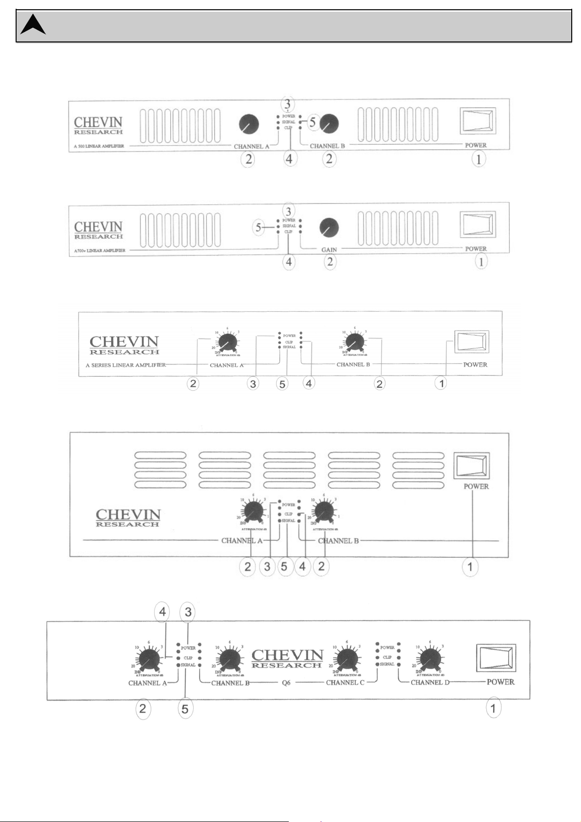
FRONT PANELS
A500
A700V
A750, A1000, A1004, A1500, A2000, A3000
A4000, A5003
Q6
Page 7
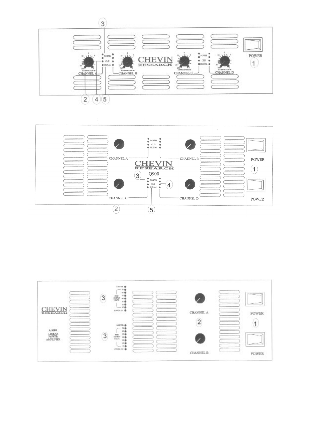
Q1004, QB1000/600
Q900
A5000 & A6000
1. Power Switch Controls the mains power supply to the amplifier
2. Output Controls Controls the output level (gain) of each channel
3. Power LEDs Top green LEDs. They illuminate when the unit is ON
4. Clip LEDs Red LEDs, one per channel. They illuminate when the unit is being driven into clip
and indicate the SoftClip system is active.
5.Singnal LEDs Bottom green LEDs. They illuminate when the signal is present
On the A500 & A700V, the signal LEDs are in the middle.
1. Power Switch Controls the mains power supply to the amplifier
2. Output control Controls the output level (gain) of each channel
3. Output Bargraph Power LED. The bottom green LED, illuminates when the unit is ON
Output Voltage LEDs. The column of green LEDs above the power LED.
These give indication of the output voltage. Output power willl be determined by load
impedance. Illumination of the 70V LED indicates imminent clipping.
Clip LED. The top red LED. It illuminates when the amplifier is being driven into clip
and indicates the SoftClip system is active. If the Clip threshold is exceeded, the
intensity of this LED provides an indication of the degree of overdrive.
Page 8
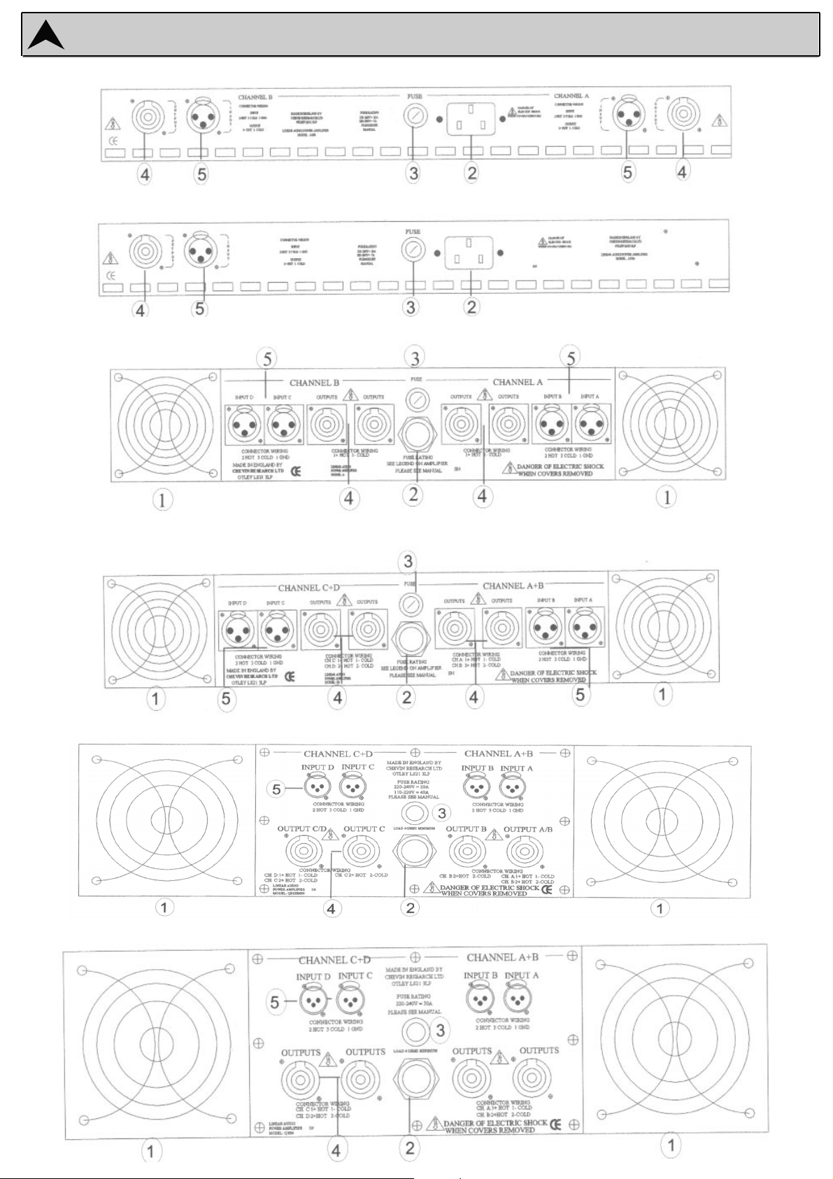
BACK PANELS
Q1004
QB1000/600
Q6
A750, A1000, A1004, A1500, A2000, A3000
A700V
A500
Page 9
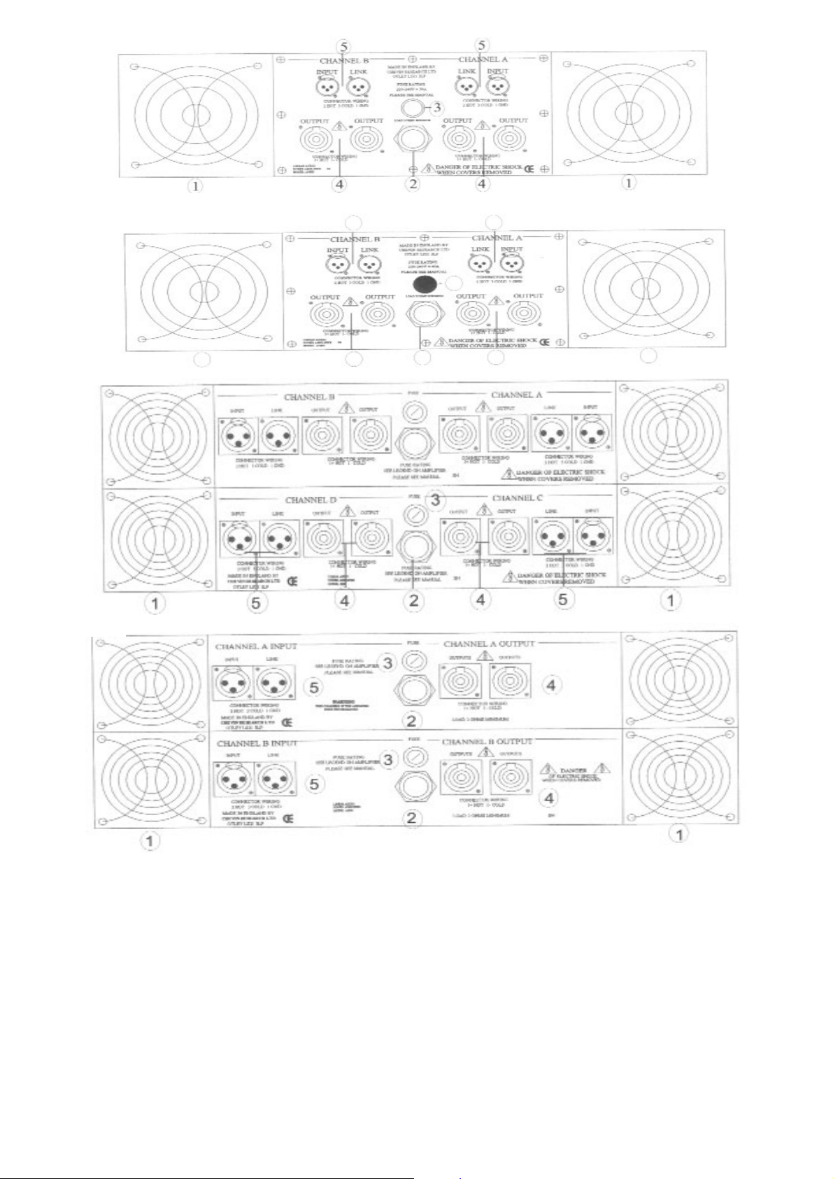
1. Vari Speed Fans
On the A500 & A700V, the fan is internal. On all other models, fans are at the back.
These spin at variable speeds depending on the signal level and ambient temperature
2. Mains Input
On the A500 & A700V, mains input is via a detachable 3-core main cable with integral connector.
All other models have a fixed, high current 3-core mains cable. Wiring as per standard European colour coding.
3. Mains Fuse
Correct fuse rating indicated on the back panel legend.
Please note the A5003 fuse is internal
4.Output Connectors Neutrik Speakon sockets.
Pin wiring indicated on legend
A500, A700, Q6, Q1004, QB1000/600: One per channel
A750, A1000, A1004, A1500, A2000, A2500, A3000, A4000, A5000, A5003. A6000, Q900: Two per channel
5. Input Connectors
XLR sockets
. Pin and wiring indicated on legend.
A500, A700v, Q6, Q1004, QB1000/600: One female XLR connector per channel.
A750, A1000, A1004, A1500, A2000, A2500, A3000, A4000, A5000, A5003, A6000, Q900
One male and one female XLR connector per channel.
A4000
A5003
Q900
A5000/A6000
1
2
3
44
44
5555
Page 10
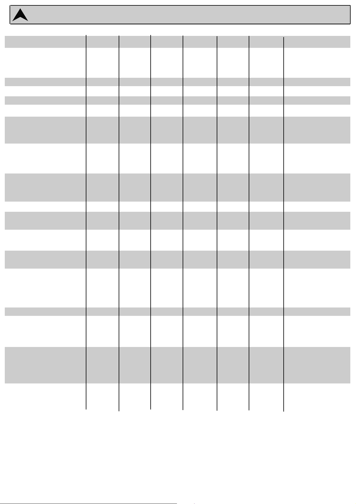
Specifications
RMS Power Output
into 4Ω, watts per channel
into 8Ω, watts per chanel
No of Channels
Power Bandwidth
+0dB, - 3dB
Slew Rate
in excess of
Gain
Total Harmonic Distortion
Typical @ 1 dB below clip
20kHz @ 1dB below clip
Signal to Noise Ratio
Typical ref. full output, unweighted
Worst case 10Hz - 30kHz
Crosstalk
Typical
Worst case 10Hz - 30kHz
Damping Factor
Input Impedance
electronically balanced
Common Mode Rejection
typically
Input Sensitivity
ref. full output into 4 ohms
Protection
Clipping
Load Below 2.4 ohms
Shorted Output, DC or RF at output
Power Consumption
Power Requirements
50/60Hz ac in volts
Internally selectable for
Dimensions
Rack Units
Height x Width x Depth in inches
Height x Width x Depth in mm
Weight
Gross in kg/lbs
Net in kg/lbs
SPECIFICATIONS
A500
350
200
2
2Hz-40kHz
40V/µs
x 37.5
0.06%
0.08%
-120dB
-95dB
-115dB
-95dB
400
10k Ohm
-70dB
IV RMS
Soft
Dynamic linear
Immediate
1.2kVA
220- 240v
100-120v
1u
1.75 x 19 x 8.5
44 x 483 x 215
5.2kg/11.5lbs
4.7kg/9lbs
A1000
600
350
2
2Hz-80kHz
75V/
µ
s
x 50
0.04%
0.07%
-125dB
-95dB
-115dB
-95dB
400
10k Ohm
-70dB
IV RMS
Soft
Dynamic linear
Immediate
2kVA
220- 240v
100-120v
2u
3.5 x 19 x 15
88 x 483 x 381
10kg/22lbs
8.4kg/18.5lbs
A1004
1000
600
2
2Hz-80kHz
75V/
µ
s
x 65
0.04%
0.07%
-125dB
-95dB
-115dB
-95dB
400
10k Ohm
-70dB
IV RMS
Soft
Dynamic linear
Immediate
3.3kVA
220- 240v
100-120v
2u
3.5 x 19 x 15
88 x 483 x 381
13.3kg/29lbs
11.7kg/26lbs
A1500
1250
650
2
2Hz-80kHz
60V/µs
x 70
0.04%
0.07%
-125dB
-95dB
-115dB
-95dB
400
10k Ohm
-70dB
IV RMS
Soft
Dynamic linear
Immediate
4kVA
220- 240v
100-120v
2u
3.5 x 19 x 15
88 x 483 x 381
14kg/31lbs
12.4kg/27lbs
Q6
600
350
4
2Hz-80kHz
75V/µs
x 50
0.04%
0.07%
-125dB
-95dB
-115dB
-95dB
400
10k Ohm
-70dB
IV RMS
Soft
Dynamic linear
Immediate
4kVA
220- 240v
100-120v
2u
3.5 x 19 x 15
88 x 483 x 381
14kg/30.9lbs
12.3kg/27lbs
Q1004
1000
600
4
2Hz-80kHz
75V/
µ
s
x 65
0.04%
0.07%
-125dB
-95dB
-115dB
-95dB
400
10k Ohm
-70dB
IV RMS
Soft
Dynamic linear
Immediate
6.6kVA
220- 240v
N/A
3u
5.25 x 19 x 15
132 x 483 x 381
16kg/34lbs
14kg/29.6lbs
QB1000/600
2 x 1000/ 2 x 600
2 x 600 / 2 x 375
4
2Hz-80kHz
75V/
µ
s
x 65 / x 50
0.04%
0.07%
-125dB
-95dB
-115dB
-95dB
400
10k Ohm
-70dB
IV RMS
Soft
Dynamic linear
Immediate
5.2kVA
220- 240v
100- 120v
3u
5.25 x 19 x 15
132 x 483 x 381
20kg/44lbs
18kg/40.5lbs
Page 11
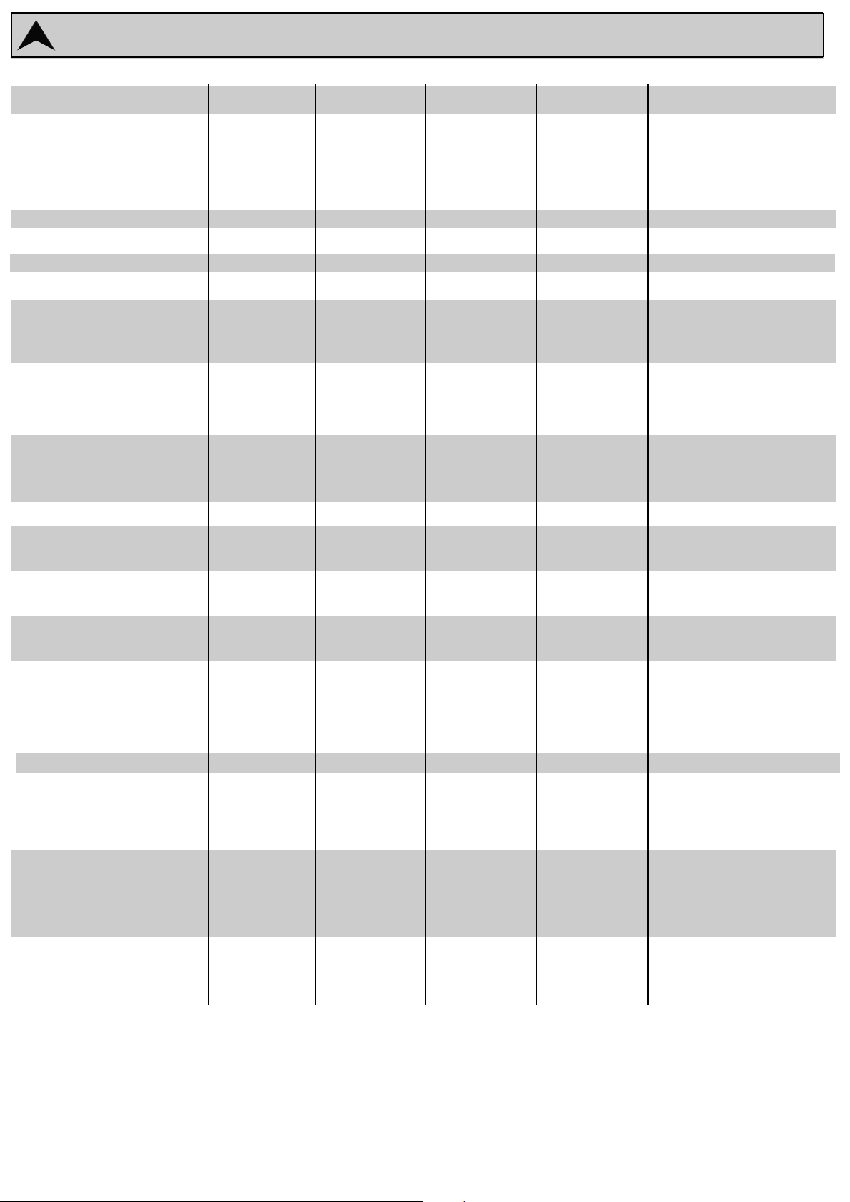
Specifications
RRMMSS PPoowweerr OOuuttppuutt
10Hz-20kHz
into 2Ω, watts per channel
into 4Ω, watts per channel
into 8Ω, watts per chanel
NNoo ooff CChhaannnneellss
PPoowweerr BBaannddwwiiddtthh
+0dB, - 3dB
SSlleeww RRaattee
in excess of
GGaaiinn
TToottaall HHaarrmmoonniicc DDiissttoorrttiioonn
Typical @ 1 dB below clip
20kHz @ 1dB below clip
SSiiggnnaall ttoo NNooiissee RRaattiioo
Typical ref. full output, unweighted
Worst case 10Hz - 30kHz
CCrroossssttaallkk
Typical
Worst case 10Hz - 30kHz
DDaammppiinngg FFaaccttoorr
IInnppuutt IImmppeeddaannccee
electronically balanced
CCoommmmoonn MMooddee RReejjeeccttiioonn
typically
IInnppuutt SSeennssiittiivviittyy
ref. full output into 4 ohms
PPrrootteeccttiioonn
Clipping
Load Below 1.2 ohms
Shorted Output, DC or RF at output
PPoowweerr CCoonnssuummppttiioonn
Power Requirements
50/60Hz ac in volts
Internally selectable for
DDiimmeennssiioonnss
Rack Units
Height x Width x Depth in inches
Height x Width x Depth in mm
WWeeiigghhtt
Gross in kg/lbs
Net in kg/lbs
SPECIFICATIONS
A2000
1200 watts
650 watts
350 watts
2
2Hz-80kHz
75V/
µ
s
x 50
0.04%
0.07%
-125dB
-95dB
-115dB
-95dB
400
10k Ohm
-70dB
IV RMS
Soft
Dynamic linear
Immediate
3.9kVA
220- 240v
100-120v
2u
3.5 x 19 x 15
88 x 483 x 381
13.3kg/29lbs
11.7kg/26lbs
A3000
1600 watts
900 watts
500 watts
2
2Hz-80kHz
50V/
µ
s
x 60
0.04%
0.07%
-125dB
-95dB
-115dB
-95dB
400
10k Ohm
-70dB
IV RMS
Soft
Dynamic linear
Immediate
5.3kVA
220- 240v
100-120v
2u
3.5 x 19 x 15
88 x 483 x 381
14kg/31lbs
12.4kg/27lbs
A4000
2000 watts
1000 watts
600 watts
2
2Hz-80kHz
65V/
µ
s
x 65
0.04%
0.07%
-125dB
-95dB
-115dB
-95dB
400
10k Ohm
-70dB
IV RMS
Soft
Dynamic linear
Immediate
6.6kVA
220- 240v
N/A
3u
5.25 x 19 x 15
132 x 483 x 381
16kg/34lbs
14kg/29.6lbs
A5003
2500 watts
1500 watts
900 watts
2
2Hz-80kHz
65V/
µ
s
x 70
0.04%
0.07%
-125dB
-95dB
-115dB
-95dB
400
10k Ohm
-70dB
IV RMS
Soft
Dynamic linear
Immediate
8kVA
220- 240v
N/A
3u
5.25 x 19 x 15
132 x 483 x 381
16kg/34lbs
14kg/29.6lbs
A6000
3000 watts
2000 watts
1200 watts
2
2Hz-50kHz
50V/
µ
s
x 90
0.04%
0.07%
-125dB
-95dB
-115dB
-95dB
400
10k Ohm
-70dB
IV RMS
Soft
Dynamic linear
Immediate
5.3kVA per channel
220- 240v
100-120v
4u
7 x 19 x 15
178 x 483 x 381
23.5kg/59lbs
21.5kg/47.4lbs
Page 12

THE CHEVIN WARRANTY
This precision engineered CHEVIN product is guaranteed against defects due to faulty materials and
workmanship for a period of 24 months from the date of the original purchase, subject to the following restrictions.
This warranty is only valid in the country of purchase
The equipment has not been abused or operated in conjunction with unsuitable or faulty apparatus.
The equipment has not been disassembled, modified or tampered with by any person other than
our CHEVIN staff or overseas by our own or distributors’ staff.
The equipment has not suffered damage in transit.
Should service be required, notify the dealer from whom you purchased the equipment to arrange for an
authorised CHEVIN agent to confirm the need for attention.
Do not dispatch the goods without the prior approval of CHEVIN or its authorised agents. If asked
to return the goods, pack carefully (preferably in the original carton) and return pre-paid.
Insurance is recommended as goods are returned at owner’s risk.
Packing insurance and freight on the return journey will be paid for by CHEVIN or its authorised
agents only if warranty work proves necessary. If warranty work proves unnecessary, goods
will be released upon payment by the owner for charges for non-warranty repair work and return packing,
insurance and freight.
The attached warranty card should be completed and returned to CHEVIN RESEARCH LTD.
Failure to register by not returning the warranty card in no way limits or invalidates the warranty, but in the event of
service being required, delay may result since warranty work cannot begin until thje original sale has been verified.
In case of difficulty, contact CHEVIN RESEARCH LTD. This warranty in no way affects your statutory rights.
Head Office: Chevin Research Ltd., 41a IIkley Road, Otley, West Yorkshire LS21 3LP ENGLAND
Tel: +44 (0)1943 466060 Fax: +44 (0)1943 466020
www.chevin-research.com
[email protected]
Trademark Acknowledgements:
Speakon is a registered trademark of Neutrik AG
XLR is a registered trademark of ITT Cannon Ltd.
This manual is intended for informational purposes only. All information included herein is subject to change without notice.
Chevin Research Ltd. shall not be held responsible for any damages, direct or indirect
arising from or relating to the use of this manual.
Chevin Research Ltd. 2003. All rights reserved.
c
 Loading...