

Chevin S1500, S1504, S2000 User Manual
USER MANUAL
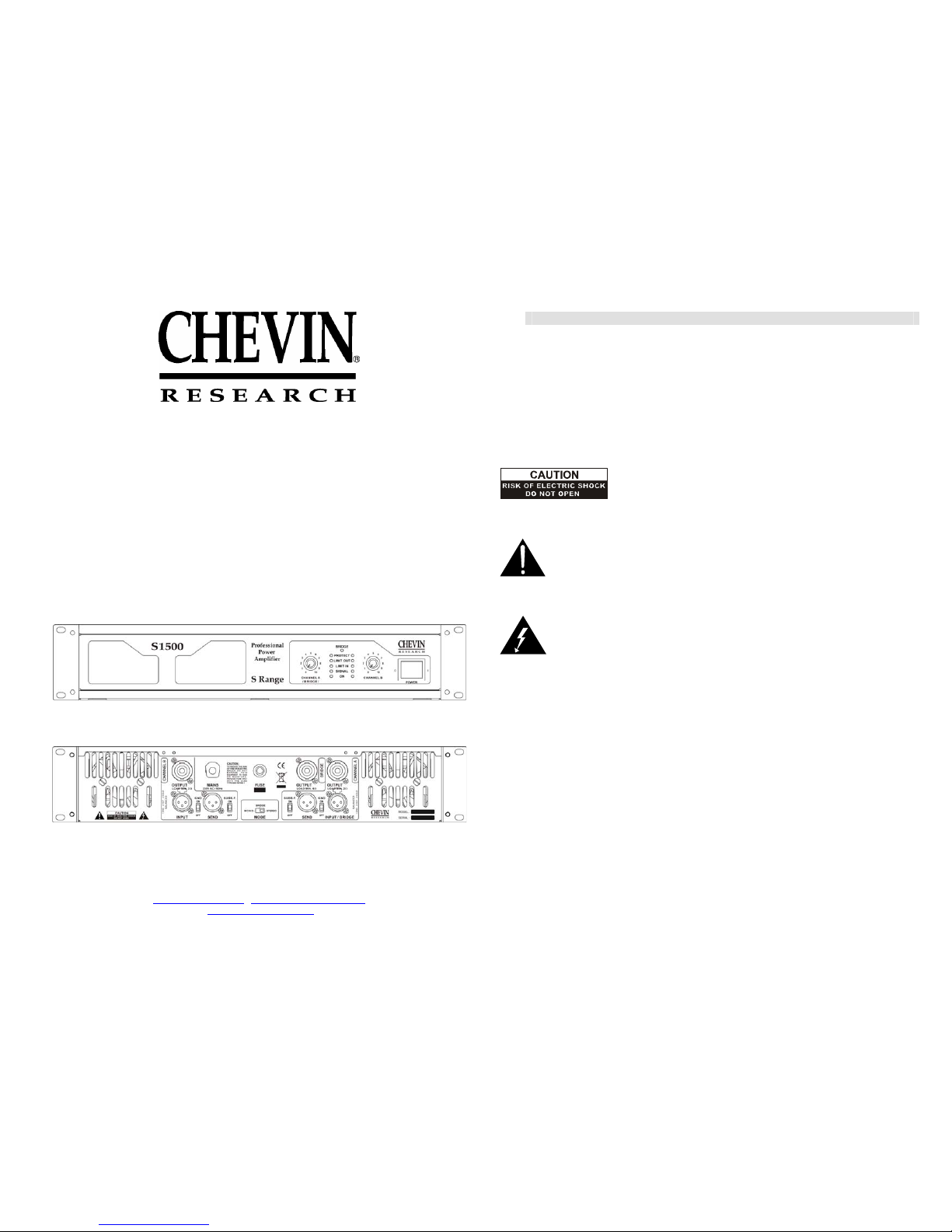
S1500/S1504/S2000
PROFESSIONAL POWER AMPLIFIER
Chevin Research, Kreuzbichlstraße 29 A-6112 Wattens, Austria
Tel/Fax: +43 (0)5224 51398
chevin.martin @aon.at , sales@chevin-research.com
www.chevin-research.com
Contents
Important Safety Instructions .................
Introduction ............................................
Front Panel ............................................
Rear Panel .............................................
Clip-Limiter ............................................
Subsonic Filter .......................................
2
3
3
4
4
5
GND Ground ..........................................
Stereo Mode ..........................................
Mono Mode ............................................
Bridge Mono Mode .................................
Installation and Dimensions .................
Technical Specifications ........................
5
5
6
7
8
11
Caution: To reduce the risk of electric shock do not remove the
cover. No user-servicable parts inside. Refer servicing to qualified service personnel.
Warning: To prevent fire or electric shock do not expose this equipment to rain or moisture.
The exclamation point within an equilateral triangle is intended to alert the user to
the presence of important operating and servicing instructions in the literature accompanying
the product.
The lightning flash with arrowhead symbol within an equilateral triangle is
intended to alert the user to the presence of uninsulted “dangerous voltage” within the
product’s enclosure that may be of sufficient magnitude to constitute a risk of electric shock.
WARNING - When using electric products basic precautions should always be followed,
including the following:
- Read all these instructions before using the product.
- Do not use the product near water e.g. near swimming pool, kitchen sink, bathtub, or
in a wet basement, etc.
- This product, either alone or in combination with other sound equipments, is capable
of producing sound levels that can cause permanent hearing loss. Do not operate
the product for a long time at high volume level.
- The product should be located away from heat sources such as direct sunlight or
other sources of heat.
- The product should be connected to a power supply only of the type marked on the
rear panel of the product.
- The power supply cord of the product should be unplugged from the mains socket
when left unused.
1 2
- Avoid allowing any objects to enter inside the product or spilling any liquid into it.
- The product should not be used when:
1. The power supply cord or plug has been damaged
2. Objects have fallen or liquid has been spilled into the product
3. The product has been exposed to rain
4. The product does not appear to operate normally or exhibits a marked change in
performance
5. The product enclosure has been damaged.
- Do not attempt to service the product. Refer servicing to qualified personnel.
The symbol of crossed-out wheeled bin is intended to inform the user that the
product is the subject to the requirements of the WEEE Directive of the European Parliament.
i.e. after the end of its lifetime the product should not be disposed as unsorted municipal waste
but should be collected separately.
Introduction
This 2-channel professional power amplifier provides high-value performance.
Features
- independent clip-limiters and subsonic filters (40Hz)
- operating modes: stereo / mono / bridge
- balanced XLR inputs
- Speakon outputs
- LED indicators for BRIDGE, PROTECT, SIGNAL, LIMIT IN, LIMIT OUT, SIGNAL,
POWER
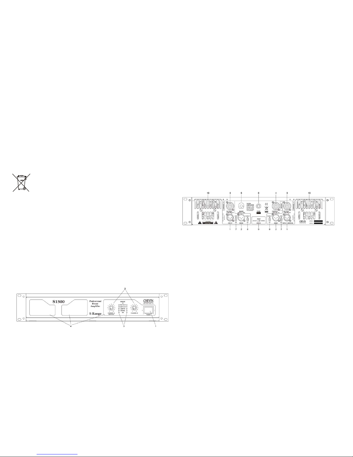
Front Panel
1. Power switch
2. Gain controls for CHANNEL A, CHANNEL B
LED indicators for respective channels
Blue ON indicators indicates that the amplifier is on, no matter if there is any input
signal.
Green SIGNAL indicators indicates the presence of the signal.
Yellow LIMIT IN and LIMIT OUT indicators indicates that limiter is activated and
reduces input or output signal.
Red PROTECT indicators indicates that the amplifier is overheated. In this case it is
recommended to reduce the gain or to switch off the amplifier until its temperature is
lower.
Yellow light of BRIDGE indicates that the amplifier works in BRIDGE mode.
4. Air inlet
Rear Panel
1. INPUT connectors for CHANNEL A and CHANNEL B
2. SEND connectors providing the same signals as A and B input signals
3. OUTPUT connectors for CHANNEL A, CHANNEL B
4. OUTPUT BRIDGE – output connector for bridge mode
5. MAINS – AC power cable
6. MAINS FUSE or BREAKER
7. GND lift switches
8. Switches for subsonic filters of CHANNEL A and CHANNEL B
9. 3-position switch for MONO / STEREO / BRIDGE
10. Air outlet
Clip-Limiter
When audio signals drive the amplifier’s output circuit beyond its power capability it clips. The
clip limiter detects this and reduces the gain to minimise the amount of overdrive.
To preserve as much of the program dynamics as possible, the clip limiter works only if clipping
occurs frequently. Each channel has its own limiter that cannot be defeated.
3
4
 Loading...