


vGauge G12P/G12S
User’s Manual
Chetco Digital Instruments

Copyright © 2008 Chetco Digital Instruments, Inc.
All rights reserved.
vGauge™ is a trademark of Chetco Digital Instruments, Inc.
SeaGauge™ is a trademark of Chetco Digital Instruments, Inc.
SeaSwitch™ is a trademark of Chetco Digital Instruments, Inc.
vDash™ is a trademark of Chetco Digital Instruments, Inc.
WARNING!
USE THIS UNIT ONLY AS AN AID TO MONITORING ENGINE
PERFORMANCE INFORMATION.
CAUTION
When showing sensor data, this unit will only show information based on the
sender used and its installed position.
The operating and storage temperature for your unit is from -4 degrees to+167
degrees Fahrenheit (-20 to +75 degrees Celsius). Extended storage temperatures
higher or lower than specified will cause the liquid crystal display to fail. Neither
this type of failure nor its consequences are covered by the warranty. For more
information, consult the factory customer service department.
All features and specifications subject to change without notice.
Chetco Digital Instruments may find it necessary to change or end our policies,
regulations, and special offers at any time. We reserve the right to do so without
notice.
All screens in this manual are simulated.
NOTICE!
Free software upgrades will be available on our website at http://
www.chetcodigital.com as they are released. Please check our website periodically
for these and other information as they become available.
Thank you for choosing Chetco Digital Instruments

This device complies with Part 15 of the FCC Rules. Operation is subject to the
following two conditions: (1) this device may not cause harmful interference, and
(2) this device must accept any interference received, including interference that
may cause undesired operation.
Note:
This equipment has been tested and found to comply with the limits for a Class B
digital device, pursuant to Part 15 of the FCC Rules. These limits are designed to
provide reasonable protection against harmful interference in a residential
installation. This equipment generates, uses and can radiate radio frequency energy
and, if not installed and used in accordance with the instructions, may cause
harmful interference to radio communications. However, there is no guarantee that
interference will not occur in a particular installation. If this equipment does cause
harmful interference to radio or television reception, which can be determined by
turning the equipment off and on, the user is encouraged to try to correct the
interference by one or more of the following measures:
• Reorient or relocate the receiving antenna.
• Increase the separation between the equipment and receiver.
• Connect the equipment into an outlet on a circuit different from that to which the
receiver is connected.
• Consult the factory customer service department for help.

SPECIFICATIONS
CASE Dimensions: ...............................................7.75” W x 6.5” H x 2.3” D
MODULE Dimensions:.......................................5.75” W x 4.6” H x 1.7” D
Input Voltage:.........................................................4.5-5.6 vDC, 5-volt Nominal
Processor Frequency:............................................ 18.432 MHz
Maximum Current:................................................800 mA
Display:.................................................................... 5.5”W x 4.5”H LCD 30 char H x 40
char W
Operating and Storage Temperature ................. -4 to +167 degrees Fahrenheit
-20 to +75 degrees Celsius
Analog Conversion Accuracy :............................10 bits
Analog update rate : .............................................. 2 per second (10 point average)
Sender voltage range:............................................ 0 -3.3 volts
Sender voltage resolution:.................................... 0.0128 volts
Pulse Count update rate: ...................................... 1 per second
Maximum Pulse Count:........................................ 500 per second
Firmware Revision:................................................ G12R1.14
NMEA 2.0 Instrumentation Sentences $IIXDR,A $IIXDR,C $IIXDR,D
$IIXDR,F $IIXDR,G $IIXDR,I $IIXDR,P $IIXDR,R $IIXDR,S $IIXDR,T
$IIXDR,U $IIXDR,V $SDDBT, $SDMTW, $GPVTG,S $GPVTG,H

Table of Contents
Table of Contents 5
Introduction 7
Welcome 7
Anti-glare faceplate 8
What You Get 9
Unit 9
Cables 9
Software 10
Operation 11
Normal Operation 13
Graphic Modes 17
System Configuration 23
Options File 24
Page Format file 35
Display Engine Hour Meter 42
Display Date/Time 43
Alarms 44
Analog Inputs 46
Connectors 51
System Power 52
Optional Analog Sensors 54
Installation 57
Cutout 57
Power 60
Alarm 60
Pulse input 60
Signals 61
Calibration Tables 62
Serial Port Protocols 65
NEXT MENU 66
SET Function 66
Real-time data 66
STOP Function 66
Program Mode 67
NMEA INPUT 69
Flash Programming 71
Unit Dimensions vGauge-G12 Case 72
Unit Dimensions vGauge-G12 Module 73
90 day Warranty 74

SeaGauge-G12 User’s Manual
6

SeaGauge-G12 User’s Manual
Introduction
Welcome
Thank you for purchasing a Chetco Digital Instruments product. vGauge G12™ is
a multi-function display head that provides custom instrumentation in a rugged
compact design. Its menu driven functions allow it adapt to and monitor many
different sensors from a single location. Optional built-in wireless capability allows
display of real-time data from remote locations.
This manual covers the vGauge G12A/vGauge G12P/ vGauge G12i /vGauge
G12S products. All are functionally the same except for screen sizes and
enclosures.
vGauge G12A features 5.7” Sunlight viewable monochrome LCD screen and
rugged Aluminum enclosure. NMEA 0183 input via USB/Serial
vGauge G12P features 5.7” Sunlight viewable monochrome LCD screen and
sealed plastic enclosure. NMEA 0183 input via USB/Serial
vGauge G12i features 5.7” Sunlight viewable monochrome LCD screen and sealed
plastic enclosure. NMEA 0183 input and 4 direct analog inputs with 1 Tachometer
input.
vGauge G12S features 3.8” Sunlight viewable monochrome LCD screen and
sealed plastic enclosure. NMEA 0183 input via USB/Serial
All products are designed to work with vGauge Remote sensor unit which provides
interface to external sensors to create a virtual instrumentation system. The vGauge
G12 display heads support both USB and Serial interfaces to vGauge Remote units
or PC.
Display data is received in digital format conforming to the NMEA 0183 serial
protocol. Up to 16 $IIXDR NMEA instrumentation sentences can be received and
displayed using a variety of user specified graphic formats.
7

SeaGauge-G12 User’s Manual
vGauge G12i models are available with 4 direct analog inputs and a single
tachometer input. These models will have an additional 6-pin connector on the rear
of the unit for receiving the additional analog inputs.
An ti -gla re face p l ate
The vGauge™ G12 display head is shipped with a protective film to prevent
damage to the faceplate during shipping. Keep the protective film in place until
finished with installation. It is easily removed by pealing off when ready for use.
The special anti-glare display window should only be cleaned with soap and water
or window cleaner. A mild dish soap works well and then rinse with clean water.
Do not wipe surface with a paper towel as it will mar the finish. A lens cleaning
tissue used for eye glasses works best. Be sure it is safe for plastic lenses and antiglare coatings.
8

SeaGauge-G12 User’s Manual
What You Get
Unit
vGauge G12 head unit with power and data input. Unit constantly monitors the
data inputs and updates the graphic LCD display two times per second. Digital data
is received from vGauge Remote sensor unit via both serial (RS232) and USB
protocols and is decoded for display based on user configured formats.
Multiple instrumentation display can be configured and scrolled though using a
sealed pushbutton on the unit. Custom configurations can be created using
supplied
USB interface.
A single water-resist connector in the rear provides a quick disconnect for both
power and data inputs. Unit can be powered directly from vGauge Remote sensor
unit or USB.
vDash software on PC and downloaded to G12 display unit using the
Cables
Maximum distance using USB is 16 feet and up to 150 feet can be achieved using
serial input. Custom interface cables are required to support both interface types
vGauge G12 is supplied with a standard USB interface cable with a maximum
length of 16 feet. One end is type A USB connector and opposite end is custom 8pin circular water-resist connector for attachment to unit.
For distances longer than 16 feet, a custom serial cable can be ordered up 150 feet.
Please contact Chetco Digital Instruments if you need a longer cable.
Flash Programming cable – A custom USB interface cable is available for
reprogramming the unit firmware. This cable is only used to reprogram the unit
and is not required for normal operations including configuration via attached PC
9

SeaGauge-G12 User’s Manual
Software
vGauge G12 units come with vDash instrumentation software for WindowsXP
and Vista platforms.
graphic elements for up to 8 user defined pages. These settings can be arranged on
the host PC connected to vGauge Remote sensor unit and then transferred to
attached vGauge G12 units via supplied USB cable.
Please consult
vDash user manual for details on user configuration.
vDash allows creation of custom screen layouts and
10

SeaGauge-G12 User’s Manual
Operation
This manual covers operation for vGauge G12 Dash units and the vGauge G12
OEM Modules. Both units feature a 320X240 graphic LCD display. Operation of
both units is the same with the exception of the location of the control buttons. On
the vGauge G12 Dash unit, the sealed button is located on the front of the case
while the vGauge G12 OEM module has a rear connector for attachment of
control buttons. The single control button provides multiple functions based on
how long it is pushed and released. Throughout the manual reference will be made
to the button as:
• BackLight On/OFF (hold and release less then 2 seconds)
• Screen Select (hold release for more then 2 seconds)
• Unit Reset (hold for more then 30 seconds)
Control of the vGauge G12 unit is done using sealed pushbutton. The Screen
Select function is used to scroll through different display pages. The Backlight
function is used to toggle the backlight on or off.
11

SeaGauge-G12 User’s Manual
When you receive your unit it has been programmed to display gauge readings in
groups with a maximum of eight groups. On power-up the unit will start to display
the first group of gauge functions. Additional gauge display groups can be viewed
by using the Select button. Push and hold the button for 2 seconds and then
release to view the next page. Once the unit has shown all display groups it cycles
over again from the first group.
The Backlight function performs two functions.
BACKLIGHT TOGGLE – Pressing during normal operation will toggle
backlight. Press and release the Select Button for one second to toggle the
backlight.
ALARM DISABLE – If alarm function is active, pressing button will deactivate
alarm for 60 seconds after which alarm will resume.
12

SeaGauge-G12 User’s Manual
Norm al Op eratio n
When the unit is powered up it will display the first group of display values. The
vGauge G12 can display from 1 to 12 values per group and up to 8 groups. The
total number of groups displayed is an option that can be changed in setup mode.
For example if the number of groups is set to four – pressing the Select button will
take you through the following possible displays.
Figure 1 Display Group 1
13
SeaGauge-G12 User’s Manual
Figure 2 Display Group 2
14
SeaGauge-G12 User’s Manual
Figure 3 Display Group 3
15

SeaGauge-G12 User’s Manual
Figure 4 Display Group 4.
Once you cycle through all display groups they start over. You can change the
group assignment and position for any of the display values using the setup modes.
16

SeaGauge-G12 User’s Manual
Graphic Modes
vGauge G12 supports ten graphics modes to display digital data. The modes can be
selected dependent on the type of desired display format.
• Digital Data Display (1)
• Histogram (2)
• Horizontal Bar Graph (4)
• Small Gauge Dial (6)
• Large Gauge Dial (8)
• Large Half Dial (9)
• Large Digital Data Display (10)
• Vertical Bar Graph (11)
• Small Digital Data Display (12)
• Huge Text Graph (13)
Graphic display modes can be combined with digital data display in each display
group. Graphic display modes are available for the analog inputs and NMEA
$IIXDR inputs. Non - NMEA $IIXDR data can be displayed using Digital Data
Display (D) only.
Graphic display modes are assigned during group configuration. As specific gauge
values are being assigned to each of the eight possible groups there is an option to
choose which display mode to use for that sensor input.
Digital Data – An 8 character text label followed by a 6 character digital readout.
The characters are 16 X 8 for a total of 12 readouts (6 rows by 2 columns) per
display page. Digital data display modes can be mixed with other graphic display
modes
Figure 5 Digital Data Element
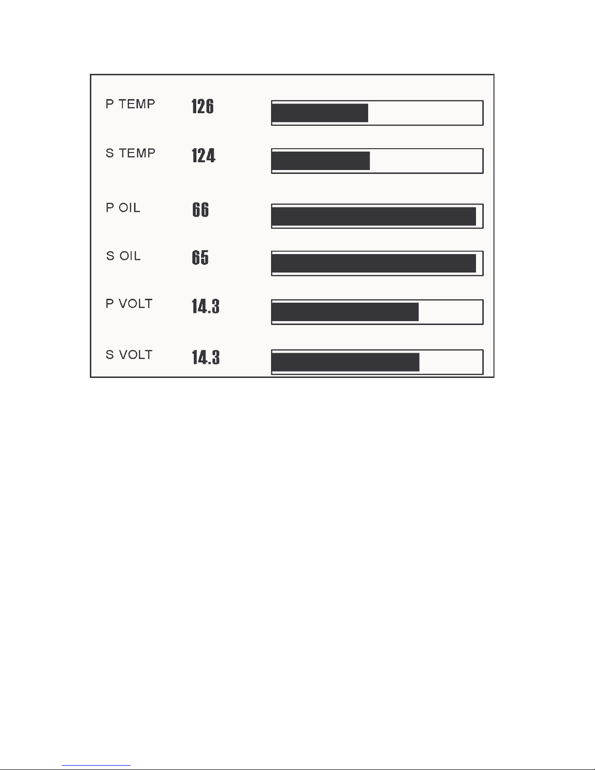
Bar Graph – 24 segment Bar graph used to show relative signal level with low
values to the left and high values to the right. Each segment contains represents
1/10th of full scale value. As sensor signal increases, the graph will grow to the
right in real time.
17

SeaGauge-G12 User’s Manual
Figure 6 Bar Graph Element
Sensor text label and digital value are displayed on the left of the graph. One Bar
Graph can be assigned to each row of the display for a total of 6 per display page.
NO OTHER GRAPHIC ELEMENTS CAN BE ASSIGNED TO THE
SAME ROW WITH THE BAR GRAPH
Histogram Graph – A 40 bar Histogram graph shows the relative strength of
sensor input over a user configured time interval. Recent time values are on the left
and oldest time values on the right. As new values arrive - the graph scrolls to the
right adding the newest value and dropping the oldest. Signal strength is depicted
by a 64 segment bar with lowest strength at the bottom and highest at the top.
Histograms show signal trends over time.
Figure 7 Histogram Graphic Element
Sensor text label and digital value are displayed on top of the graph. One
Histogram Graph uses 10 rows of the display. There can be three Histograms per
group.
NO OTHER GRAPHIC ELEMENTS CAN BE ASSIGNED TO THE
SAME ROWS WITH THE HISTOGRAM
18

SeaGauge-G12 User’s Manual
Digital Gauge Dial Graph – A 15 segment digital dial shows the relative signal
strength using a analog style gauge display.
The needle at the 9:00 O’clock position represents low
signal
The needle at the 12:00 O’clock represent Mid-strength
The needle at the 3:00 O’clock represents Max strength
The needle moves in real-time in a clockwise direction to represent the relative
strength of the analog signal.
Sensor text label is displayed in small text under the dial and digital sensor readout
is display in center of dial using larger text.
Each display page can have up to 12 digital dial elements arranged as 3 rows of 4
elements. Other graphic elements can be mixed with digital dial displays.
19
SeaGauge-G12 User’s Manual
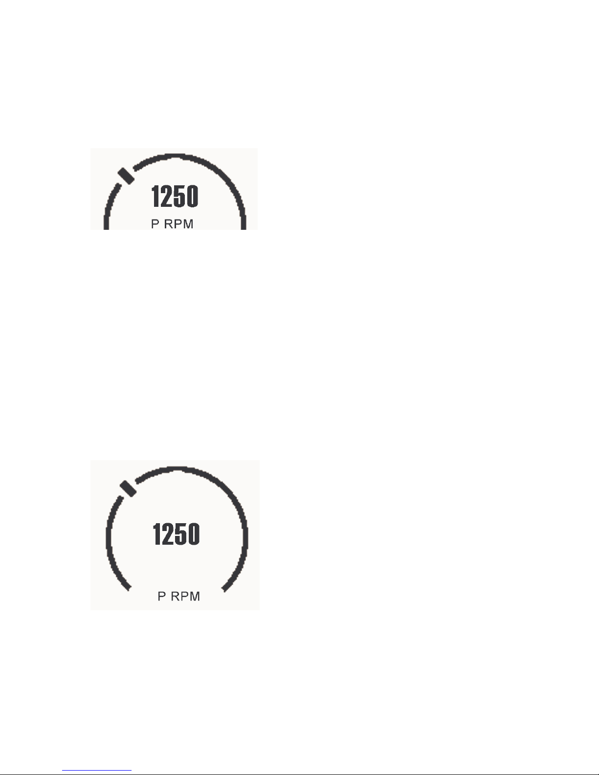
Large Half Digital Dial – This graphic mode shows relative signal strength using
a familiar dial display with a 14 element needle around the other edge. As sensor
value increases, the needle moves in a clockwise direction This graph is an
instantaneous display of signal strength.
Figure 8 Large Half Dial Display Mode
Sensor text label is display in small text below dial and digital readout of sensor is
shown in the middle using large text.
Six Large Half Digital Dials can be used on a single display page arranged as three
rows and two columns. A Large Half Digital Dial can be combined with other
graphic elements as long as they do not overlap the dial position.
Large Full Digital Dial – This graphic mode shows relative signal strength using
a familiar dial display with a 24 element needle around the other edge. As sensor
value increases, the needle moves in a clockwise direction This graph is an
instantaneous display of signal strength.
Figure 9 Large Full Dial Display Mode
Sensor text label is display in small text below dial and digital readout of sensor is
shown in the middle using large text.
20

SeaGauge-G12 User’s Manual
Four Large Digital Dials can be used on a single display page arranged as two rows
and two columns. A Large Digital Dial can be combined with other graphic
elements as long as they do not overlap the dial position.
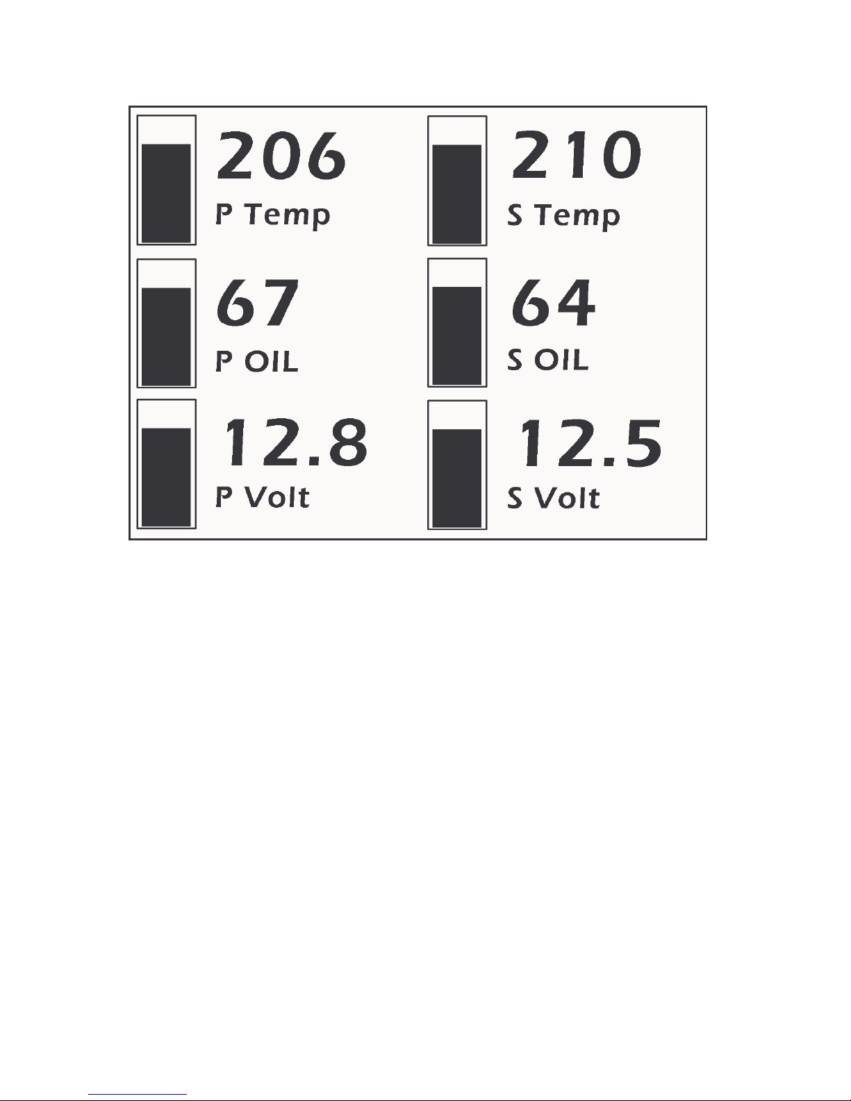
Big Vertical Bar – This graphic mode shows relative signal strength using a
vertical bar display with a 20 elements and a large digital readout. As sensor value
increases, the bars fill in from bottom to top. When bar fill in, the signal is at
maximum strength. Up to 6 Vertical Bar graphs can be shown on one screen. This
graph is an instantaneous display of signal strength.
Figure 10 Big Vertical Bar Display Mode
Sensor text label is display in small text below dial and digital readout of sensor is
shown on top using large text.
Huge Text Bar – This graphic mode shows large digital readout. Text shows
instantaneous readout of sensor values in a large banner across the screen. Up to 3
Huge Text displays can be shown on one screen. This graph is an instantaneous
display of signal strength.
Figure 11 Huge Text Display Mode
Sensor text label is displayed on Left side and a huge numerical readout of sensor
value is on the right. No other items can be placed on the same row and the mode
fills all 4 columns of the display
NO OTHER GRAPHIC ELEMENTS CAN BE ASSIGNED TO THE
SAME ROW WITH THE HUGE TEXT BAR GRAPH
21

SeaGauge-G12 User’s Manual
Small Digital Data – An 8 character text label followed by a 6 character digital
readout. The characters are 8 X 6 for a total of 24 readouts (12 rows by 2 columns)
per display page. Digital data display modes can be mixed with other graphic
display modes
Figure 9 Small Digital Data Element
All Display pages are configurable to use any of the graphic display formats for
each sensor input. It is possible to mix some graphic display formats on the same
page. For example –
Figure 10 Mixed Display modes
These can be configured by using the display setup options in the SETUP MODE
entered by pressing the Option Set button
22

SeaGauge-G12 User’s Manual
System Configuration
System configuration consists of:
• Disable Alarms
• Turn Backlight ON/OFF (LCD ONLY)
• Enter Screen Contrast
• Enter Display Labels
• Enter NMEA TAGS
• Select Display Graphics Modes
• Select Display Groups
• ENTER Alarm values
These functions can be performed by using supplied
Windows PC and then download configurations to unit via USB cable.
Please refer to the
configure your vGauge display unit.
NO ADJUSTMENTS CAN BE MADE DIRECTLY TO UNIT WITOUT
PC INTERFACE.
The most common task is configuration of display labels and choosing display
graphics modes. It is always important to set Display Labels first as other
operations use them. Having incorrect display labels will make other steps
confusing and difficult. There are 12 analog sensor inputs, 6-12 NMEA inputs, and
0-2 Pulse Inputs for a total of 16 possible Display Labels
Once Display Labels are chosen the next step is to decide where to place them on
the display. Most graphic modes have only a few options while Digital Data can be
placed almost anywhere. The most common problem is placing two or more values
on the same location or on overlapping locations. Take care to map out all possible
combinations to avoid overlap.
vDash User’s Manual for detailed information on how to
vDash software on a
The final step is assigning gauge readings to groups and picking the graphic display
modes to best view the data. A group is collection of information presented on the
main display. vGauge G12 can have up to 8 groups or pages. Any Display Label
and associated sensor can be assigned to any of the 8 groups. Most groups hold
from 1 to 12 gauge readings depending on the chosen graphics display format.
23

SeaGauge-G12 User’s Manual
Options File
Most vGauge G12 configurations are contained in a separate Options file created
by the
or Serial cable.
Use the
The options file is used to configure each unit
While it is not necessary to create or edit the options file directly, it can be useful to
understand its format. Not all values in the options file are used for the vGauge
G12 since the options file may be shared with vGauge Remote and other vGauge
products.
vDash Program and transferred to flash memory from a PC using a USB
vDash configuration program to edit any vGauge12 settings.
• Disable Alarms
• Set alarm parameters
• Set number of display pages
• Set data input ports and rates
• Set screen contrast (select models)
• Turn Start up Backlight ON/OFF
• Set NMEA input modes
Value Description Index
db %05 Number of display pages 0
db %00 NOT USED 1
db %04 NOT USED 2
db %00 Number of analog inputs (select
models only)
db %00 Number of NMEA inputs 4
db %00 NOT USED 5
db %08 DISPLAY TYPE 6
db %26 Screen Contrast 7
db %1E P0 Scale factor (select models only) 8
db %4B P0 Time constant(select models only) 9
3
24

SeaGauge-G12 User’s Manual
db %00 Pulse0 Enable(select models only) 10
db %01 P0 Edge(select models only) 11
db %1E P1 Scale factor (not used) 12
db %4B P1 Time (not used) 13
db %00 Pulse1 Enable (not used) 14
db %01 P1 Edge (not used) 15
db %03 Data input ports 0=Serial 1=USB
16
2=Both
db %00 Data Out (not used) 17
db %00 NOT USED 18
db %1E Serial Baud Rate 120 = 9600
19
30=38600 20=57400
db %00 NOT USED 20
db %00 NOT USED 21
db %01 Display Labels 0=Master mode (Uses
22
local labels) 1=Slave mode (uses
remote labels)
db %00 NOT USED 23
db %01 Alarm Enable 0=disable 1=enable 24
db %00 NOT USED 25
db %00 Invert Display 1=invert 26
db %E3 Backlight POWER ON (greater then
27
%80 )
db %04 Scroll Button NOT USED 28
db %02 Set Button NOT USED 29
db %10 Pulse0 Dial Scale factor (select
30
models only)
db %10 Pulse1 Dial Scale factor NOT USED 31
db %86 Input Channel 0 (< then %80 is
32
NMEA, >%80 Analog)
db %85 Input Channel 1 (< then %80 is
33
NMEA, >%80 Analog)
db %84 Input Channel 2 (< then %80 is
34
NMEA, >%80 Analog)
db %83 Input Channel 3 (< then %80 is
35
NMEA, >%80 Analog)
db %82 Input Channel 4 (< then %80 is
36
NMEA, >%80 Analog)
db %81 Input Channel 5 (< then %80 is
37
NMEA, >%80 Analog)
db %80 Input Channel 6 (< then %80 is 38
25

SeaGauge-G12 User’s Manual
NMEA, >%80 Analog)
db %87 Input Channel 7 (< then %80 is
39
NMEA, >%80 Analog)
db %88 Input Channel 8 (< then %80 is
40
NMEA, >%80 Analog)
db %89 Input Channel 9 (< then %80 is
41
NMEA, >%80 Analog)
db %CC Input Channel 10 (< then %80 is
42
NMEA, >%80 Analog)
db %8B Input Channel 11 (< then %80 is
43
NMEA, >%80 Analog)
db %8C Input Channel 12 (< then %80 is
44
NMEA, >%80 Analog)
db %8D Input Channel 13 (< then %80 is
45
NMEA, >%80 Analog)
db %8E Input Channel 14 (< then %80 is
46
NMEA, >%80 Analog)
db %8F Input Channel 15 (< then %80 is
47
NMEA, >%80 Analog)
db %00 Output Channel 0 Map 48
db %01 Output Channel 1 Map 49
db %02 Output Channel 2 Map 50
db %03 Output Channel 3 Map 51
db %04 Output Channel 4 Map 52
db %05 Output Channel 5 Map 53
db %06 Output Channel 6 Map 54
db %07 Output Channel 7 Map 55
db %08 Output Channel 8 Map 56
db %09 Output Channel 9 Map 57
db %0A Output Channel 10 Map 58
db %0B Output Channel 11 Map 59
db %0C Output Channel 12 Map 60
db %0D Output Channel 13 Map 61
db %0E Output Channel 14 Map 62
db %0F Output Channel 15 Map 63
db %25 ALARM 0 LOW VALUE 64
db %FF ALARM 0 HIGH VALUE 65
db %00 ALARM 1 LOW VALUE 66
db %FF ALARM 1 HIGH VALUE 67
db %00 ALARM 2 LOW VALUE 68
db %FF ALARM 2 HIGH VALUE 69
26

SeaGauge-G12 User’s Manual
db %00 ALARM 3 LOW VALUE 70
db %FF ALARM 3 HIGH VALUE 71
db %00 ALARM 4 LOW VALUE 72
db %FF ALARM 4 HIGH VALUE 73
db %00 ALARM 5 LOW VALUE 74
db %FF ALARM 5 HIGH VALUE 75
db %00 ALARM 6 LOW VALUE 76
db %FF ALARM 6 HIGH VALUE 77
db %00 ALARM 7 LOW VALUE 78
db %FF ALARM 7 HIGH VALUE 79
db %00 ALARM 8 LOW VALUE 80
db %FF ALARM 8 HIGH VALUE 81
db %00 ALARM 9 LOW VALUE 82
db %FF ALARM 9 HIGH VALUE 83
db %00 ALARM 10 LOW VALUE 84
db %FF ALARM 10 HIGH VALUE 85
db %00 ALARM 11 LOW VALUE 86
db %FF ALARM 11 HIGH VALUE 87
db %00 ALARM 12 LOW VALUE 88
db %00 ALARM 12 HIGH VALUE 89
db %00 ALARM 13 LOW VALUE 90
db %FF ALARM 13 HIGH VALUE 91
db %00 ALARM 14 LOW VALUE 92
db %FF ALARM 14 HIGH VALUE 93
db %00 ALARM 15 LOW VALUE 94
db %FF ALARM 15 HIGH VALUE 95
db %00 NOT USED 96
db %00 NOT USED 97
db %00 NOT USED 98
db %00 NOT USED 99
db %00 NOT USED 100
db %00 NOT USED 101
db %00 NOT USED 102
db %00 NOT USED 103
db %00 NOT USED 104
db %00 NOT USED 105
db %00 NOT USED 106
db %00 NOT USED 107
db %00 NOT USED 108
db %00 NOT USED 109
27

SeaGauge-G12 User’s Manual
db %00 NOT USED 110
db %00 NOT USED 111
db %00 NOT USED 112
db %00 NOT USED 113
db %00 NOT USED 114
db %00 NOT USED 115
db %00 NOT USED 116
db %00 NOT USED 117
db %00 NOT USED 118
db %00 NOT USED 119
db %00 NOT USED 120
db %00 NOT USED 121
db %00 NOT USED 122
db %00 NOT USED 123
db %00 NOT USED 124
db %00 NOT USED 125
db %00 NOT USED 126
db %00 NOT USED 127
db %01 INVERT FLAG Channel 0 128
db %00 INVERT FLAG Channel 0 129
db %01 INVERT FLAG Channel 1 130
db %00 INVERT FLAG Channel 1 131
db %00 INVERT FLAG Channel 2 132
db %01 INVERT FLAG Channel 2 133
db %00 INVERT FLAG Channel 3 134
db %01 INVERT FLAG Channel 3 135
db %00 INVERT FLAG Channel 4 136
db %01 INVERT FLAG Channel 4 137
db %00 INVERT FLAG Channel 5 138
db %01 INVERT FLAG Channel 5 139
db %00 INVERT FLAG Channel 6 140
db %01 INVERT FLAG Channel 6 141
db %00 INVERT FLAG Channel 7 142
db %01 INVERT FLAG Channel 7 143
db %01 INVERT FLAG Channel 8 144
db %00 INVERT FLAG Channel 8 145
db %01 INVERT FLAG Channel 9 146
db %00 INVERT FLAG Channel 9 147
db %00 INVERT FLAG Channel 10 148
db %01 INVERT FLAG Channel 10 149
28

SeaGauge-G12 User’s Manual
db %01 INVERT FLAG Channel 11 150
db %00 INVERT FLAG Channel 11 151
db %00 INVERT FLAG Channel 12 152
db %00 INVERT FLAG Channel 12 153
db %00 INVERT FLAG Channel 13 154
db %00 INVERT FLAG Channel 13 155
db %00 INVERT FLAG Channel 14 156
db %00 INVERT FLAG Channel 14 157
db %00 INVERT FLAG Channel 15 158
db %00 INVERT FLAG Channel 15 159
db %00 NOT USED 160
db %00 NOT USED 161
db %00 NOT USED 162
db %00 NOT USED 163
db %00 NOT USED 164
db %00 NOT USED 165
db %00 NOT USED 166
db %00 NOT USED 167
db %00 NOT USED 168
db %00 NOT USED 169
db %00 NOT USED 170
db %00 NOT USED 171
db %00 NOT USED 172
db %00 NOT USED 173
db %00 NOT USED 174
db %00 NOT USED 175
db %00 NOT USED 176
db %00 NOT USED 177
db %00 NOT USED 178
db %00 NOT USED 179
db %00 NOT USED 180
db %00 NOT USED 181
db %00 NOT USED 182
db %00 NOT USED 183
db %00 NOT USED 184
db %00 NOT USED 185
db %00 NOT USED 186
db %00 NOT USED 187
db %00 NOT USED 188
db %00 NOT USED 189
29

SeaGauge-G12 User’s Manual
db %00 NOT USED 190
db %00 NOT USED 191
db %00 USB AUTODET(Not Used) 192
db %00 USB 1 ENABLE (Not Used) 193
db %00 USB 2 ENABLE (Not Used) 194
db %00 USB STATUS (Not Used) 195
db %00 SIO0 ENABLE (Not Used) 196
db %00 SIO1 ENABLE (Not Used) 197
db %03 USB BAUDRATE 1=9600 2=1800
198
3=38400 4=57600
db %00 (Not Used) 199
db %1F OPTIONS RPM2 SCALE(Not Used) 200
db %4B OPTIONS RPM2 TIME(Not Used) 201
db %04 OPTIONS RPM2 ENABLE(Not
202
Used)
db %01 OPTIONS RPM2 EDGE(Not Used) 203
db %01 OPTIONS P2 DIAL SCAL (Not
204
Used)
db %00 OPTIONS RPM3 TIME 205 205
db %00 OPTIONS RPM3 ENABLE 206 206
db %00 OPTIONS RPM3 EDGE 207 207
db %01 OPTIONS TIMER0ENABLE 208 208
db %01 OPTIONS TIMER1ENABLE 209 209
db %01 OPTIONS TIMER2ENABLE (must
210
be %01)
db %01 OPTIONS TIMER3ENABLE 211 211
db %00 OPTIONS TIMER0 HB 212 212
db %01 OPTIONS TIMER0 LB 213 213
db %00 OPTIONS TIMER1 HB 214 214
db %01 OPTIONS TIMER1 LB 215 215
db %FF OPTIONS TIMER2 HB 216
db %FF OPTIONS TIMER2 LB 217
db %FF OPTIONS TIMER3 HB 218 218
db %FF OPTIONS TIMER3 LB 219 219
db %02 OPTIONS BASE TIMMER (must be
220
%02)
db %00 (Not Used) 221
db %FF OPTIONS LCD TEMP ADJ 222 222
db %00 (Not Used) 223
db %00 (Not Used) 224
db %00 (Not Used) 225
30

SeaGauge-G12 User’s Manual
db %00 (Not Used) 226
db %00 (Not Used) 227
db %00 (Not Used) 228
db %00 (Not Used) 229
db %00 (Not Used) 230
db %00 (Not Used) 231
db %00 (Not Used) 232
db %00 (Not Used) 233
db %00 (Not Used) 234
db %00 (Not Used) 235
db %00 (Not Used) 236
db %00 (Not Used) 237
db %00 (Not Used) 238
db %00 (Not Used) 239
db %00 (Not Used) 240
db %00 (Not Used) 241
db %00 (Not Used) 242
db %00 (Not Used) 243
db %00 (Not Used) 244
db %00 (Not Used) 245
db %00 (Not Used) 246
db %00 (Not Used) 247
db %00 (Not Used) 248
db %00 (Not Used) 249
db %00 (Not Used) 250
db %00 (Not Used) 251
db %00 (Not Used) 252
db %00 (Not Used) 253
db %00 (Not Used) 254
db %00 (Not Used) 255
db %00 LCD TEMPERATURE ADJUST
256
Table (Select Models)
31
SeaGauge-G12 User’s Manual
The
vDash configuration program is used to set or change any options and will
construct the correct OPTIONS File to be loaded into vGauge G12 Flash memory.
The options settings are very similar to vGauge Remote sensor units with a few
exceptions.
vGauge Section
Be sure the unit type is set to G12 Landscape (320 X 240) or G12 Portrait (240 X
320). The display can be configured with either orientation
32

SeaGauge-G12 User’s Manual
Serial/USB0 Section
The NMEA inputs need to be enabled (checked) to receive any data from a
vGauge Remote Sensor unit. NMEA data can be received from both USB and
Serial ports. It is best to keep both ports enabled.
The Mode should be set to SLAVE to allow vGauge G12 to display sensor labels
and calibrated readings from a vGauge Remote sensor unit. Setting Mode to
MASTER will instruct the vGauge G12 to ignore the sensor labels from the
NMEA data and use the matching labels stored internally (LABELS tab). This
could be useful when using multiple display heads and wishing to have different
senor names at different locations (engine room or helm station)
USB1/USB2 Section
Set the Baud rate to match the source of the NMEA data (default is 57600)
Input Section
Set Analog to 0 (default) if being used as a display head for vGauge Remote. If unit
is configured for direct analog inputs, set to 4 channels.
Pages value determines the number of display screens that can be scrolled through
using the SELECT button. Once the limit is reached, the pages reset to and start
over.
Pulse 2 Section
vGauge G12 uses an internal timer to perform pulse rate calculations and output
NMEA data. The Setting default is TimeBase2 and should not be changed. There is
no advantage to selecting other values and doing so could result in instability.
LCD Display Section
Various display options can be set depending on the particular model and screen.
The Backlight On at Start turns the backlight on when the unit powers up.
Backlight can still be toggled by press and release of SELECT button for 2
33

SeaGauge-G12 User’s Manual
seconds. For best viewing in day and low conditions, the backlight should be left
on.
The Backlight Adjust setting sets the brightness of the backlight. Minimum value is
0 (off) and maximum value is 100 (full on).
The Contrast setting will lighten or darken the display. Maximum value is 255
(lightest) and minimum value is 0 (darkest). Not all units support contrast
adjustment. Some screens have built-in temperature compensated features and
require no adjustment under normal operating conditions.
When making contrast adjustment on enabled units, it is possible to choose a
setting that is too dark or light to see anything. If this happens, revert to previous
value and reload Options file. Be careful to only make small adjustments and
record previous settings. Also, when making contrast adjustments – only
change one value (contrast).
Some units have an option to perform temperature based contrast adjustments
outside of the normal operating conditions. This should only be used when
operating under extreme temperature conditions (less then 10F or over 120 F).
Under normal conditions, built-in temperature compensation of screen contrast
will be sufficient.
34

SeaGauge-G12 User’s Manual
Page Format file
The Page Format file is created by the vDash application and downloaded into
non-volatile memory (FLASH) and does not need to be directly edited.
The file allows display graphic elements to be assigned to each possible channel for
each of 8 display page groups
The ten display mode symbols are:
• |0| - not assigned to the group
• |1| - Digital Data Display Mode
• |2| - Histogram Graph
• |4| - Bar Graph
• |6| - Digital Gauge
• |8| - Large Half Dial Gauge
• |9| - Large Full Dial Gauge
• |10| - Large Digital Text
• |11| - Vertical Bar Graph
• |12| -Small Digital Text
• |13| - Huge Digital Text
For example the following entry would assign 6 small dials and 2 large dials to the
first display page group
db %06 DISPLAY CHANNEL 00-PAGE 00
db %06 DISPLAY CHANNEL 01-PAGE 00
db %00 DISPLAY CHANNEL 02-PAGE 00
db %06 DISPLAY CHANNEL 03-PAGE 00
db %06 DISPLAY CHANNEL 04-PAGE 00
db %00 DISPLAY CHANNEL 05-PAGE 00
db %06 DISPLAY CHANNEL 06-PAGE 00
db %06 DISPLAY CHANNEL 07-PAGE 00
db %00 DISPLAY CHANNEL 08-PAGE 00
db %00 DISPLAY CHANNEL 09-PAGE 00
db %00 DISPLAY CHANNEL 10-PAGE 00
db %00 DISPLAY CHANNEL 11-PAGE 00
35

SeaGauge-G12 User’s Manual
db %00 DISPLAY CHANNEL 12-PAGE 00
db %00 DISPLAY CHANNEL 13-PAGE 00
db %09 DISPLAY CHANNEL 14-PAGE 00
db %09 DISPLAY CHANNEL 15-PAGE 00
36

SeaGauge-G12 User’s Manual
The location of each graphic element on a page is determined by a index to a
screen position. The entire 320X240 graphic space is divided to 24 regions where
elements can be assigned
The Position Index determines the display location of the selected sensor value on
the 40X30 character display matrix as outlined below.
0 0 0 0 0 0 0 0 0 0 1 1 1 1 1 1 1 1 1 1 2 2 2 2 2 2 2 2 2 2 3 3 3 3 3 3 3 3 3 3
0 0 0 0 0 0 0 0 0 0 1 1 1 1 1 1 1 1 1 1 2 2 2 2 2 2 2 2 2 2 3 3 3 3 3 3 3 3 3 3
0 0 0 0 0 0 0 0 0 0 1 1 1 1 1 1 1 1 1 1 2 2 2 2 2 2 2 2 2 2 3 3 3 3 3 3 3 3 3 3
0 0 0 0 0 0 0 0 0 0 1 1 1 1 1 1 1 1 1 1 2 2 2 2 2 2 2 2 2 2 3 3 3 3 3 3 3 3 3 3
0 0 0 0 0 0 0 0 0 0 1 1 1 1 1 1 1 1 1 1 2 2 2 2 2 2 2 2 2 2 3 3 3 3 3 3 3 3 3 3
4 4 4 4 4 4 4 4 4 4 5 5 5 5 5 5 5 5 5 5 6 6 6 6 6 6 6 6 6 6 7 7 7 7 7 7 7 7 7 7
4 4 4 4 4 4 4 4 4 4 5 5 5 5 5 5 5 5 5 5 6 6 6 6 6 6 6 6 6 6 7 7 7 7 7 7 7 7 7 7
4 4 4 4 4 4 4 4 4 4 5 5 5 5 5 5 5 5 5 5 6 6 6 6 6 6 6 6 6 6 7 7 7 7 7 7 7 7 7 7
4 4 4 4 4 4 4 4 4 4 5 5 5 5 5 5 5 5 5 5 6 6 6 6 6 6 6 6 6 6 7 7 7 7 7 7 7 7 7 7
4 4 4 4 4 4 4 4 4 4 5 5 5 5 5 5 5 5 5 5 6 6 6 6 6 6 6 6 6 6 7 7 7 7 7 7 7 7 7 7
8 8 8 8 8 8 8 8 8 8 9 9 9 9 9 9 9 9 9 9 10 10 10 10 10 10 10 10 10 10 11 11 11 11 11 11 11 11 11 11
8 8 8 8 8 8 8 8 8 8 9 9 9 9 9 9 9 9 9 9 10 10 10 10 10 10 10 10 10 10 11 11 11 11 11 11 11 11 11 11
8 8 8 8 8 8 8 8 8 8 9 9 9 9 9 9 9 9 9 9 10 10 10 10 10 10 10 10 10 10 11 11 11 11 11 11 11 11 11 11
8 8 8 8 8 8 8 8 8 8 9 9 9 9 9 9 9 9 9 9 10 10 10 10 10 10 10 10 10 10 11 11 11 11 11 11 11 11 11 11
8 8 8 8 8 8 8 8 8 8 9 9 9 9 9 9 9 9 9 9 10 10 10 10 10 10 10 10 10 10 11 11 11 11 11 11 11 11 11 11
12 1 2 12 12 12 12 12 12 12 12 13 13 13 13 13 13 13 13 13 13 14 14 14 14 14 14 14 14 14 14 15 15 15 15 15 15 15 15 15 15
12 1 2 12 12 12 12 12 12 12 12 13 13 13 13 13 13 13 13 13 13 14 14 14 14 14 14 14 14 14 14 15 15 15 15 15 15 15 15 15 15
12 1 2 12 12 12 12 12 12 12 12 13 13 13 13 13 13 13 13 13 13 14 14 14 14 14 14 14 14 14 14 15 15 15 15 15 15 15 15 15 15
12 1 2 12 12 12 12 12 12 12 12 13 13 13 13 13 13 13 13 13 13 14 14 14 14 14 14 14 14 14 14 15 15 15 15 15 15 15 15 15 15
12 1 2 12 12 12 12 12 12 12 12 13 13 13 13 13 13 13 13 13 13 14 14 14 14 14 14 14 14 14 14 15 15 15 15 15 15 15 15 15 15
16 16 16 16 16 16 16 16 16 16 17 17 17 17 17 17 17 17 17 17 18 18 18 18 18 18 18 18 18 18 19 19 19 19 19 19 19 19 19 19
16 16 16 16 16 16 16 16 16 16 17 17 17 17 17 17 17 17 17 17 18 18 18 18 18 18 18 18 18 18 19 19 19 19 19 19 19 19 19 19
16 16 16 16 16 16 16 16 16 16 17 17 17 17 17 17 17 17 17 17 18 18 18 18 18 18 18 18 18 18 19 19 19 19 19 19 19 19 19 19
16 16 16 16 16 16 16 16 16 16 17 17 17 17 17 17 17 17 17 17 18 18 18 18 18 18 18 18 18 18 19 19 19 19 19 19 19 19 19 19
16 16 16 16 16 16 16 16 16 16 17 17 17 17 17 17 17 17 17 17 18 18 18 18 18 18 18 18 18 18 19 19 19 19 19 19 19 19 19 19
20 20 20 20 20 20 20 20 20 20 21 21 21 21 21 21 21 21 21 21 22 22 22 22 22 22 22 22 22 22 23 23 23 23 23 23 23 23 23 23
20 20 20 20 20 20 20 20 20 20 21 21 21 21 21 21 21 21 21 21 22 22 22 22 22 22 22 22 22 22 23 23 23 23 23 23 23 23 23 23
20 20 20 20 20 20 20 20 20 20 21 21 21 21 21 21 21 21 21 21 22 22 22 22 22 22 22 22 22 22 23 23 23 23 23 23 23 23 23 23
20 20 20 20 20 20 20 20 20 20 21 21 21 21 21 21 21 21 21 21 22 22 22 22 22 22 22 22 22 22 23 23 23 23 23 23 23 23 23 23
20 20 20 20 20 20 20 20 20 20 21 21 21 21 21 21 21 21 21 21 22 22 22 22 22 22 22 22 22 22 23 23 23 23 23 23 23 23 23 23
37

SeaGauge-G12 User’s Manual
The following table sets the positions for each element on the first page
db %00 POSITION 00 - PPOS0
db %03 POSITION 01 - PPOS0
db %00 POSITION 02 - PPOS0
db %08 POSITION 03 - PPOS0
db %0B POSITION 04 - PPOS0
db %00 POSITION 05 - PPOS0
db %10 POSITION 06 - PPOS0
db %13 POSITION 07 - PPOS0
db %00 POSITION 08 - PPOS0
db %00 POSITION 09 - PPOS0
db %00 POSITION 10 - PPOS0
db %00 POSITION 11 - PPOS0
db %00 POSITION 12 - PPOS0
db %00 POSITION 13 - PPOS0
db %0D POSITION 14 - PPOS0
db %01 POSITION 15 - PPOS0
These settings would create the following screen format for the first page
38

SeaGauge-G12 User’s Manual
The Page Format file contains 15 pairs for Format and position assignments but
only the first 8 are used.
39

SeaGauge-G12 User’s Manual
The final entry in the Page Format file is the NMEA tag assignment table
db %00 POSITION 00 - NMEA
db %00 POSITION 01 - NMEA
db %00 POSITION 02 - NMEA
db %00 POSITION 03 - NMEA
db %00 POSITION 04 - NMEA
db %00 POSITION 05 - NMEA
db %00 POSITION 06 - NMEA
db %00 POSITION 07 - NMEA
db %00 POSITION 08 - NMEA
db %00 POSITION 09 - NMEA
db %00 POSITION 10 - NMEA
db %00 POSITION 11 - NMEA
db %E1 POSITION 12 - NMEA
db %D1 POSITION 13 - NMEA
db %00 POSITION 14 - NMEA
db %00 POSITION 15 – NMEA
This table assigns selected NMEA 0183 tags to selected channels for display at the
specified location. A non-zero entry in a specific channel location will decode that
NMEA string and place it according to chosen graphic and location.
40

SeaGauge-G12 User’s Manual
The following table shows the currently available tags that can be captured and
displayed. Once a selected tag is detected for the designated display label, the data
is decoded and displayed if that label is assigned to a Display Group. NMEA data
can only be displayed in Digital Data format..
INDEX NMEA TAG Function
0x00 $IIXDR,G Instrumentation Data
0x10 $GPGGA UTC TIME, Position, Sat info
0x20 $GPVTG Track and ground speed
0x30 $SDDBT depth below transducer
0x40 $SDMTW water temperature
0x50 $GPRMC Position, ground speed, true heading
0x60 $GPRMB Destination WP position, Bearing to WP,
Closing speed to WP, Distance to WP
0x70 $VWVHW Speed and heading
0x80 $VWVLW Water traveled distance
0xA0 $SDDPT depth below transducer
0xB0 $GPGLL Basic position
0xC0 $SDVHW Sonar Water Speed and heading
0xD0 $PCDIS,T Custom tag for DATE TIME
0xE0 $PCDIS,H Custom tag for Engine Hour Meter Display
0xF0 $GPRMC Used for adjusted UTC time to local time
All NMEA tags use a comma “,” to separate data fields in the NMEA sentence.
The lower half (nibble) if the index determines which position to extract.
A value of 0x25
th
The example pulls the 5
data position to obtain the GPS Speed in knots.
is important to always pair the selected NMEA tags with the correct Display
Labels. This flexibility allows freedom to choose any text label for selected NMEA
data.
If the same NMEA Tag is used in more then one display location, both locations
will receive random updates.
41

SeaGauge-G12 User’s Manual
For example, here are two NMEA display positions (NMEA0 and NMEA1) with
two different Display Labels (SPEED1 and SPEED2) looking for the same NMEA
TAG ($GPVTG).
In this case both NMEA positions will receive random updates since it is
impossible to determine which location to assign the incoming data to. It is
important to avoid using the same NMEA TAG in multiple display location with
the exception of $IIXDR, G tags.
The unit handles $IIXDR,G tags differently to allow multiple display positions. For
example, here are two NMEA display positions (NMEA0 and NMEA1) with two
different Display Labels (TEMP1 and TEMP2) looking for the same NMEA TAG
($IIXDR).
In the case of $IIXDR,G tags, display positions are determined by looking at the
last character of the Data Label field of the incoming NMEA sentence.
$IIXDR,X,DATA,U,LABEL,CHECKSUM
• X = sensor type (G,P,C,..)
• DATA = 8 character sensor data value returned from the lookup table
• U = unit of measurement specifier
• LABEL = 8 character sensor label and a 1 character number representing
the channel
• CHECKSUM = NEMA check sum calculation on the string
EXAMPLE - $IIXDR,G, 175.6,D,TEMP1 1,*45
All vGauge units append a sequential number to the end of the LABEL field that
corresponds to the display position assigned on that unit. This allows other units to
decode that number and place the received data in the correct location on the slave
unit. Multiple vGauge units can cascade data while sharing the same $IIXDR.G tag.
Display En gine Hour Meter
A special NMEA tag ($PCDIS,H) is reserved for allowing display of the internal
Engine Hour Meter in one of the NMEA data positions. Selecting this tag for any
of the NMEA positions will display a 40 character readout of the current hour
tachometers with the display label assigned to the selected NMEA position. This
display is Text readout only.
42

SeaGauge-G12 User’s Manual
Displ ay Date/Time
A special NMEA tag ($PCDIS,T) is reserved for allowing display of the internal
Date and Time in one of the NMEA data positions. Selecting this tag for any of the
NMEA positions will display a 16 character readout of the current Date and time
with the display label assigned to the selected NMEA position. This display is Text
readout only.
43
SeaGauge-G12 User’s Manual
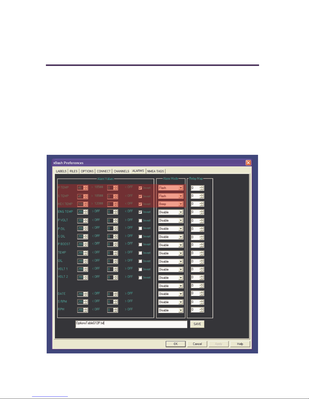
Alarms
vGauge G12 display units are capable of indicating alarms for each of the NMEA
or Analog inputs NMEA $IIXDR sentences contain a sensor value index (0-255)
that can be used to lookup user defined alarm thresholds for both Low and High
conditions. The alarms are set using the
same manner as setting alarms for any vGauge Remote sensor unit. Individual
alarm values are stored in the Options file which is latter loaded into Flash Memory
by the
The following screen shows an example of setting 3 high temperature alarms.
vDash application.
vDash configuration application in the
44

SeaGauge-G12 User’s Manual
vGauge G12 parses incoming NMEA $IIXDR sentences and extracts the raw
sensor index value
This value is then compared according to the user specified conditions from the
Alarm Options and the indicated action performed. The Alarm Mode determines
what action is taken for each individual sensor input.
Alarm Mode = Disabled results in no alarm indication
Alarm Mode = Flash will flash the indicated sensor value on the display if
currently shown.
Alarm Mode = Beep will sound an internal buzzer if the sensor is in alarm. It will
also flash the display value if shown.
All other Alarm Modes do not apply to vGauge G12 Display heads.
Important Note – When using
vDash to set alarms for vGauge G12 display
units – it is important to be sure the correct corresponding calibration tables are
chosen for each sensor to achieve the desired conditions.
vGauge G12i units must have the correct calibration tables loaded for the analog
inputs to achieve the desired alarm conditions.
45

SeaGauge-G12 User’s Manual
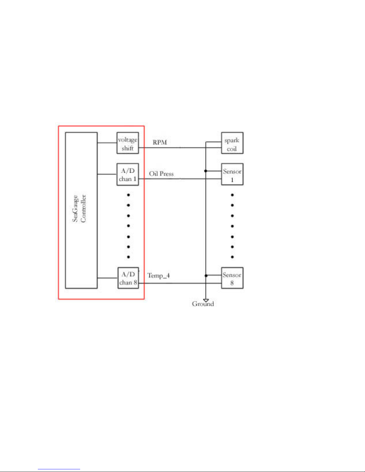
Analog Inputs
vGauge G12i units are configured with 4 analog inputs and one pulse (tachometer)
input. These Display units can be operated stand-alone without a vGauge Remote
sensor unit.
A separate 6-pin connector in the rear is used for interface to analog signals from
temperature, pressure, fuel, or voltage sensors.
Configuration and operation is the same as all other G12 units except for assigning
the NMEA input channels used for analog input.
When attached to a vGauge Remote, input data is received via NMEA 0183
$IIXDR sentence digital protocol which maps sensor reading to each of 16
channels for possible display on the display head. For analog inputs, some of the 16
NMEA input are reassigned to analog mode. vGauge G12i use NMEA channels 8
– 11 for analog mode and NMEA channel 15 for pulse (tachometer) input. Units
configured for analog inputs can still receive NMEA digital data on other channels
via USB or serial inputs
46

SeaGauge-G12 User’s Manual
The re-assignment of NMEA channels for analog mode is performed by using the
vDash program on a PC and loading the modified options file to the display
head. The following table shows a typical modified section in the Options File for
setup in analog mode.
db %86 NMEA CHANNELS 00
db %85 NMEA CHANNELS 01
db %84 NMEA CHANNELS 02
db %83 NMEA CHANNELS 03
db %82 NMEA CHANNELS 04
db %81 NMEA CHANNELS 05
db %80 NMEA CHANNELS 06
db %87 NMEA CHANNELS 07
db %08 ANALOG CHANNELS 08
db %09 ANALOG CHANNELS 09
db %0A ANALOG CHANNELS 10
db %0B ANALOG CHANNELS 11
db %8C NMEA CHANNELS 12
db %8D NMEA CHANNELS 13
db %8E NMEA CHANNELS 14
db %0F PULSE CHANNELS 15
47

SeaGauge-G12 User’s Manual
The
vDash applaction has a Channels section to allow for resetting NMEA
channels 8-11 for analog input.
In addition to channel assignment, then Options File is also modified to indicate
the number of analog inputs (0-4).
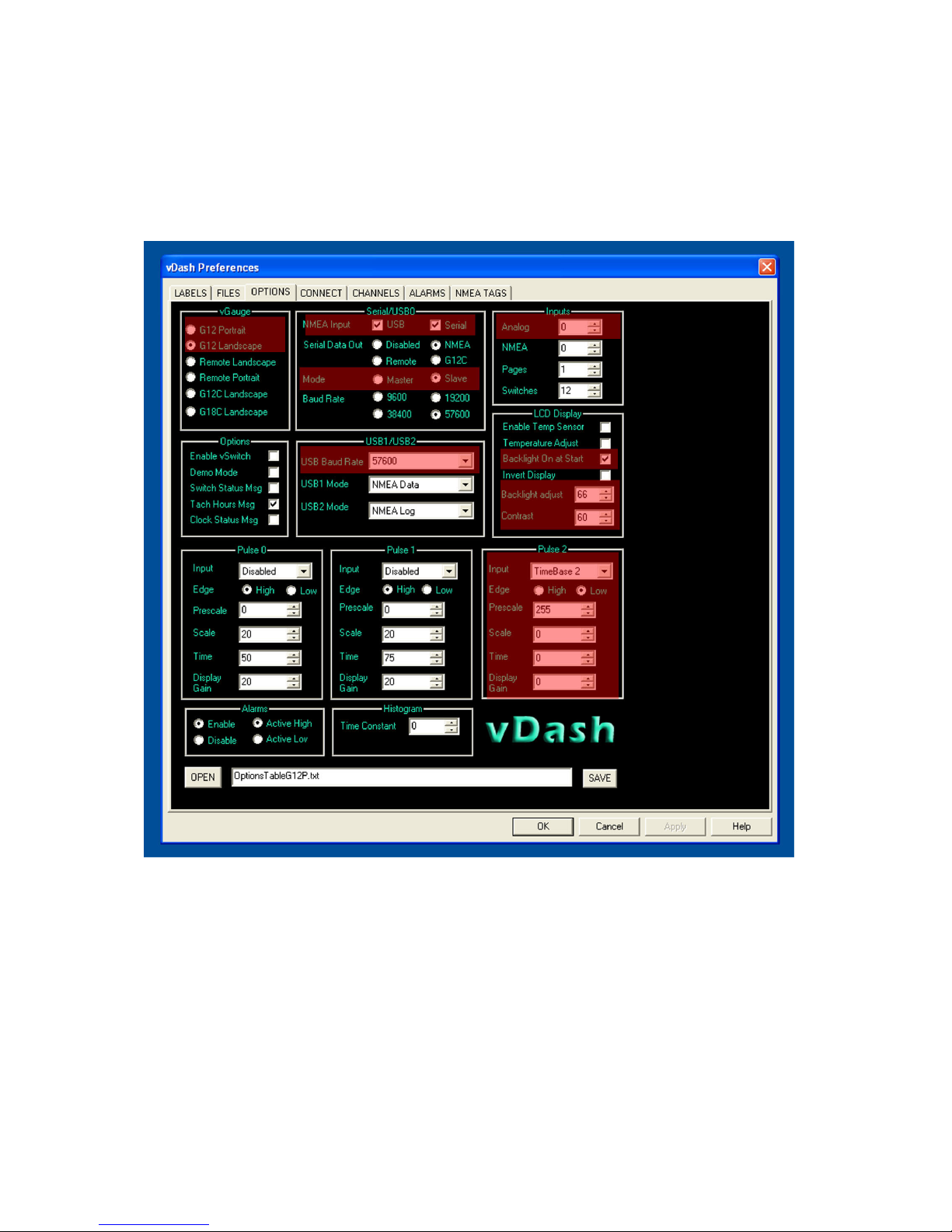
The following screen shows a typical Options screen in
configured for use on a vGauge G12i display head with 4 analog inputs and 1
tachometer input.
vDash which is
48

SeaGauge-G12 User’s Manual
Note the Analog setting in the Input section is set to 4 and that the Pulse 0 section
has enabled to allow for tachometer function.
When purchasing G12i display units from Chetco Digital Instruments with analog
input options, be sure to specify which type of sender is going to used on each
analog channel to ensure proper operation. Typical configuration is as:
Channel Function Termination
Channel 8 Temperature 300 OHM Pullup
Channel 9 Pressure 50 OHM Pullup
Channel10 Fuel 50 OHM Pullup
Channel 11 Volt 1/11 Divider
Channel 15 Tachometer Pulse 0-12V
49

SeaGauge-G12 User’s Manual
50

SeaGauge-G12 User’s Manual
Connectors
The vGauge G12P/G12S display unit has single water-resist quick-connect
connector on the rear panel (two for G12i with analog input option). Each
connector is keyed to ensure proper alignment when attaching the supplied cables.
Never force a cable in. Rotate the cable until the keys align and it should smoothly
insert.
The 8-pin Power/USB cable (P1) it typically used for direct attachment to a
vGauge Remote sensor unit. The interface contains both Power (+5V) and digital
data.
Rear View SeaGauge-G12P Case
51

SeaGauge-G12 User’s Manual
System Power
System power is supplied via the 8-pin power/USB connector. G12P/G12S units
can be powered directly from +5V USB bus.
POWER (P2)
Pin
1
2
3
4
5
6
7
8
Color Function Direction Volt
Green USBP IN 0-5
Orange/White Serial IN 0-5
Blue Flash OUT 0-5
Brown & Brown/White Power IN 5V/12V*
Blue/White Flash IN 0-5
Green/White Serial OUT 0-5
White USBM IN 0-5
Green & Orange Ground IN 0
* vGauge G12i units with analog input options are designed to be powered
by positive (+) 12 volt battery systems and will not work directly off USB
power without an adapter.
vGauge G12P/G12S display units designed to work directly off USB bus (from PC
or vGauge Remote sensor unit) will be supplied with a custom USB type A to 8Pin cable adapter which provide both power and a digital data. The cable can be
plugged directly into host PC USB port or vGauge Remote Host USB port.
For distances longer then the specified 16 foot maximum of USB cable length, a
optional serial cable interface can be obtained for distances up to 150 feet.
Contact Chetco Digital Instruments to order a custom length serial cable for your
installation.
52

SeaGauge-G12 User’s Manual
The serial port connector provides the interface to a computer RS232 interface for
command and status control of the unit. The unit can be remotely controlled via
this interface using ASCII command sequences or the optional software utilities.
Status information is transmitted out this interface using NMEA 0185 $IIXDR
sentences. Status information includes current gauge readings and display labels.
Cables are supplied for connection to this interface and there should be no need to
interface directly. A serial interface cable is normally used to remotely control the
unit or to collect status information in NMEA 0185 format. A separate
reprogramming (FLASH) cable is used if the unit needs to be reprogrammed. This
cable is compatible with RS232 protocols but requires special software to provide
this function. This cable is supplied only with the purchase of the development kit.
5VPOWER is a 5.0 volt regulated input from USB power source. This signal
should not be used for any other purpose. Maximum output is 500 mA and is not
fuse protected.
FLASH TX is the serial transmit line for reprogramming the unit. It is compatible
with standard RS232 transmit protocols
FLASH RX is the serial receive line for reprogramming the unit. It is compatible
with standard RS232 receive protocols
SERIAL1TX is the serial transmit line for status information from the unit. It is
compatible with standard RS232 transmit protocols
SERIAL1RX is the serial receive line for control information to the unit. It is
compatible with standard RS232 receive protocols
USBP is then positive USB digital signal input
USBM is then negitive USB digital signal input
SERIALGND is the serial ground. It is compatible with standard RS232 transmit
protocols.
53

SeaGauge-G12 User’s Manual
Optional Analog Sensors
The analog sensor connector on vGauge G12i units is used to interface with
various senders to provide information to the unit. The supplied color-coded cable
will have to be terminated to the appropriate senders dependent on your
application. The information supplied in the following table is typical but may be
different dependent on your application.
There are two basic classes of senders – those that provide a resistive load to
ground and those that provide a voltage.
Senders that provide a resistance to ground (temperature/pressure) are easily
interfaced by using a pull-up resistance. This resistance should be set to the midrange resistance of the selected sender.
Senders that produce a voltage need to limit the full range voltage to no more then
2.5 volts. These senders will require a voltage divider (series/pull-down) to scale
the range down to 2.5 volt max. For example – to support a voltage reading of 0-
27.5 volts requires a scale down of 2.5/11 = 0.091 Using the voltage divider
calculation of Vout = Vin (Rpd/(Rpd + Rs)) if we set Rpd to 1000 and Rs to
10000, the resulting divider is 1/11 = 0.091.
54
SeaGauge-G12 User’s Manual
The standard vGauge-G12i configuration for direct analog input is to provide 1
temperature sender input, 1 voltage input, 1 fuel level input, 1 pressure inputs, and
1 tachometer input.
• Temperature Inputs – These inputs are designed to be used with
standard coolant senders with a resistance of 1000 ohms at 70 degrees F.
Most VDO and GM style senders fit into this range.
• Voltage Inputs – These inputs use a voltage divider ratio of 1/11 and
can accept input voltages up to 27.5 volts. Do not connect to a voltage
source greater then 28 volts or damage to the unit will result.
• Pressure Inputs – These inputs are designed to be used with standard oil
pressure senders of 0-45 PSI and an resistance range of 0 – 200 ohms.
Most VDO and GM style senders fit into this range.
• Tachometer Inputs – These inputs are designed to be used with pulse
inputs of 0.5 to 12V. The multi-function input can interface directly with
flywheel inductive pickups, HAL effect, negative spark coil, VDO tach
generators, and some alternators.
The vGauge-G12i can be ordered with any combination of Rpu, Rpd, and Rs for
each of the eight sensor inputs that match your application. Contact Chetco Digital
Instruments for your custom application.
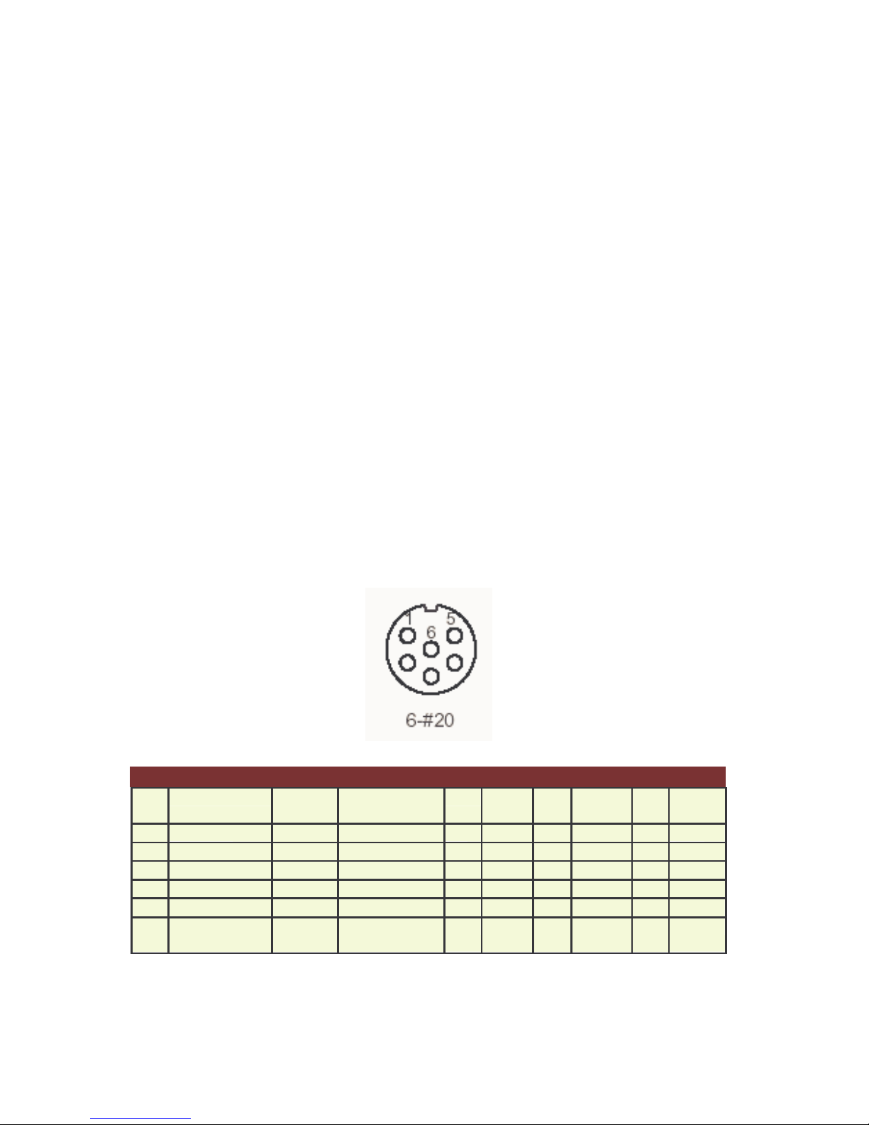
SIGNAL (P1)
Pin Color Channel Function Pull-
Up Ω
1 Green/White A8 TEMP1 R36 300 R26 - R16 2 Blue A9 PRESSURE R35 50 R25 - R15 3 Brown P0 TACH - - - - - -
4 Blue/White A10 FUEL R33 50 R23 1000 R13 5000
5 Orange/White 11 VOLT R32 - R22 1000 R12 10000
6 Orange &
Green
A1 Ground - - - - - -
Pull-
Down Ω
Series
Ω
55

SeaGauge-G12 User’s Manual
56

SeaGauge-G12 User’s Manual
Installation
Cutout
vGauge-G12 can be mounted directly in the dash by performing a rectangular cut
out as shown in the figure. The bezel lip is 0.5” from the cutout dimensions so care
must be taken to not to make the cutout any larger then specified. It is a good idea
to practice on scrap material before cutting into the panel. You must allow for the
1.5” depth of the unit plus another 4” to support the cables for a total of 6” behind
the dash.
The G12P cutout dimensions are 7.17” X 5.71”
The G12A cutout dimensions are 7.125” X 5.4”
vGauge G12P Rear case dimensions
57

SeaGauge-G12 User’s Manual
vGauge G12A Rear case dimensions
The unit can be secured in place by using slotted “L” brackets in the threaded
gimbal holes on either side of the unit. Be careful not to tighten down the supplied
screws into the holes with out a washer or “L” bracket - else damage to the internal
seal will result.
58

SeaGauge-G12 User’s Manual
vGauge-G12 OEM MODULE can be mounted directly in the dash by
performing a rectangular cut out a shown in the figure. You must allow for the 1.5”
depth of the unit plus another 3.5” to support the cables for a total of 5” behind
the dash.
The cutout dimensions are 3.5” X 2” to allow for the display area. Four
mounting holes are required as shown in the diagram.
The unit can be secured in place by using bolts through the mounting holes. Do
not let the glass of the display touch the dash. Use standoffs and foam tape to
insolate the glass from the rear of the dash. The module should be suspended by
the mounting bolts only.
59

SeaGauge-G12 User’s Manual
Power
Power is supplied from the accessory bus via a 2 amp fuse. Never attempt to
connect power without providing a fused input or serious damage may result. Unit
should have power applied when key is in the accessory or run position and power
removed when key is off.
Be sure to attach ground lead to a solid ground bus for proper operation. All
sensor/sender grounds should be attached to the same ground buss.
Alarm
The vGauge G12 contains an internal buzzer which will sound when any of the
sensor inputs exceed the preset alarm conditions.
To momentarily deactivate the alarm for 60 seconds, press and release the select
button on the front of the case with-in 2 seconds
Pulse input
The vGauge G12i unit can detect and count voltage pulses. This is typically used
for RPM or MPH calculations. Signals feed into the pulse input should be 5 – 12
volts referenced to ground and not exceed 14 volts. This input is normally attached
to the tachometer signal and can be run in parallel with existing gauges. Be careful
that the supplied signal does not contain large voltage transients or permanent
damage may result. Use caution when connecting directly to the negative terminal
of the ignition coil as large voltage spikes may occur if not properly filtered.
60
SeaGauge-G12 User’s Manual
Signals
The vGauge G12i unit supports up to 5 sensor inputs (4 analog and 1 pulse). Refer
to the connector diagrams for the proper connection for each type of sender. Any
unused sensors should be connected to ground to avoid unwanted noise. Never
connect any resistive sensor input (temperature/pressure) directly to a voltage
source or damage to the unit may result.
61

SeaGauge-G12 User’s Manual
Calibration Tables
vGauge G12i utilizes 12 modifiable calibration tables to convert sensor data into
user readable display information. The internal Analog-to-Digital converter
converts sensor voltages to 10-bit values. The converter can resolve voltages to
2.5/1024 = 2.5 mVolts. These values are averaged and then used to lookup 8
character values form a 256 point lookup table. The use of a lookup table allows
for accurate readings from non-linear sensors like temperature senders. The lookup
table also allows for easy modification of display values to suit individual
preferences and senders.
Following is an example of a partial table used to display battery voltage. The actual
table has 256 indexed values. The measured voltage has a range from 0 to 2.5 volts.
In this example it is desired to measure battery voltage from 0 to 18 volts so the
input voltage from the battery is scaled down using a voltage divider ratio of 2.5/18
= 0.1388. The scaled down voltage is converted to an averaged digital value and
then used as an index lookup in the table. For example an Input voltage of 1.178
volts becomes index value 18 in the table which corresponds to the 8 character
display value of 1.1 vdc. Using this method allows the SeaGauge-G12 to display
just about any range of values form a large variety of sensors/senders.
Index Input Voltage Measured
Voltage
1
2
3
4
5
6
7
8
9
10
11
12
13
14
15
16
0.065 0.012968
0.131 0.025936
0.196 0.038904
0.262 0.051872
0.327 0.06484
0.393 0.077808
0.458 0.090776
0.523 0.103744
0.589 0.116712
0.654 0.12968
0.720 0.142649
0.785 0.155617
0.851 0.168585
0.916 0.181553
0.981 0.194521
1.047 0.207489
Display value
0 vdc
0.1 vdc
0.1 vdc
0.2 vdc
0.3 vdc
0.3 vdc
0.4 vdc
0.5 vdc
0.5 vdc
0.6 vdc
0.7 vdc
0.7 vdc
0.8 vdc
0.9 vdc
0.9 vdc
1.0 vdc
62

SeaGauge-G12 User’s Manual
The calibration table must conform to a strict format to be loaded. The first row of
the text file must start with “[TABLE] [Table Address] [Num of Characters per line
= 8] [Number of lines = 256]” to indicate to the download program it is a text file.
The remaining 256 lines are the display lookup values corresponding to each of 256
table indexes. No extra spaces or other symbols can be inserted as the file is parsed
by position.
Following is an example of a partial table used to display battery voltage. The actual
table has 256 indexed values.
0 1 2 3 4 5 6 7 8 9 10 11 12 13 14 15 16 17 18 19 20 17
[ T A B L E] [ C 0 0 0 ] [ 8 ] [ 2 5 6 ]
d b ‘ 0 . 0 0 0 ‘ ; 0 0 0
d b ‘ 0 . 1 0 0 ‘ ; 0 0 1
d b ‘ 0 . 1 0 0 ‘ ; 0 0 2
d b ‘ 0 . 2 0 0 ‘ ; 0 0 3
d b ‘ 0 . 3 0 1 ‘ ; 0 0 4
d b ‘ 0 . 3 0 1 ‘ ; 0 0 5
d b ‘ 0 . 4 0 1 ‘ ; 0 0 6
d b ‘ 0 . 5 0 1 ‘ ; 0 0 7
d b ‘ 0 . 5 0 2 ‘ ; 0 0 8
d b ‘ 0 . 6 0 2 ‘ ; 0 0 9
d b ‘ 0 . 7 0 2 ‘ ; 0 1 0
d b ‘ 0 . 7 0 2 ‘ ; 0 1 1
d b ‘ 0 . 8 0 3 ‘ ; 0 1 2
d b ‘ 0 . 9 0 3 ‘ ; 0 1 3
d b ‘ 0 . 9 0 3 ‘ ; 0 1 4
d b ‘ 1 . 0 0 3 ‘ ; 0 1 5
d b ‘ 1 . 1 0 4 ‘ ; 0 1 6
d b ‘ 1 . 1 0 4 ‘ ; 0 1 7
d b ‘ 1 . 2 0 4 ‘ ; 0 1 8
d b ‘ 1 . 3 0 4 ‘ ; 0 1 9
• Column 0-3 must be “db ‘” to indicate start of data field
• Column 4-9 is the 6 character display value associated with the table index
• Column 10-11 is two character (HEX) used for graphic display lookup
• Column 12-13 must be “’;” to indicate end of display values
• Column 14 – is a comment and usually is the table row index number for
reference
63

SeaGauge-G12 User’s Manual
The 6 character display value can be any alpha-numeric value but usually is a
numeric sequence representing the desired readout for the given table index. The
“*” character is reserved to skip the space when displaying the sequence. For
example ‘ 1.3**04” will only display the 4 character value “ 1.3”. Most display
values will only be 4 characters long.
The 2 character HEX Graphic Display Lookup value is used to calibrate the
graphic displays. The values range for 0x00 Hex to 0x3F Hex (63 decimal) were
0x3F represents the maximum range for the graphic display. Normally these values
can increase in a linear fashion form 0x00 to 0x3F. However, they can be adjusted
in a non-linear sequence to give graphic displays more resolution in a desired
operating range. For example if it is desired to have more sensitivity at vehicle
operating temperature of 180 F, these values can be adjusted so graphic displays
ramp quickly and then level off.
Less sensitive graphic display More sensitive graphic display
db ' 55F 20' ; 164
db ' 60F 20' ; 165
db ' 65F 20' ; 166
db ' 70F 20' ; 167
db ' 75F 21' ; 168
db ' 80F 21' ; 169
db ' 85F 21' ; 170
db ' 90F 21' ; 171
db ' 95F 22' ; 172
db '100F 22' ; 173
db '105F 22' ; 174
db '110F 22' ; 175
db '155F 31' ; 229
db '160F 32' ; 230
db '165F 33' ; 231
db '170F 34' ; 232
db '175F 35' ; 233
db '180F 36' ; 234
db '185F 37' ; 235
db '190F 38' ; 236
db '195F 39' ; 237
db '200F 3A' ; 238
db '205F 3B’ ; 239
db '210F 3C' ; 240
Each table has 2048 characters to modify and there are 88 choices for each
character for a total of over 18,000 character choices for each table. For this reason
the tables are much too large to be modified directly from the Setup Mode.
However table files can be obtained and downloaded to the unit to allow for
modification of any table. All that is needed is a computer interface (RS232 or
Bluetooth) and a communication program such as HyperTerminal or the
utility.
Contact Checto Digital Instruments or http://www.chetcodigital.com/support.htm
for more information on obtaining additional table files to match particular
senders/sensors.
vDash
64

SeaGauge-G12 User’s Manual
Serial Port Protocols
The serial port interface of the SeaGauge-G12 unit can be used for real-time status
and reprogramming. The status information is sent in NMEA 0183 format using
the $IIXDR sentence format. Custom NMEA control sentences are used to
control the unit via the serial port interface.
To access the serial port information – connect the supplied cable to computer
RS232 port. Set the baud rate of the computer interface to match the baud rate of
the unit (57200 or 9600). Use the standard 8 bits, no parity, and 1 stop bit (8-N-1).
Start a serial interface program such as HyperTerminal with these settings then
power up the unit. If the connection is correct you will status message from the
unit –
vGauge Version 2.02. This indicates the settings are correct.
NMEA 0183 support custom message formats for command and control of
propriety equipment. SeaGauge uses the sentence structures:
$PCDIC,X - for control were X is the control command
• N = Next menu. Same as pressing the top button
• S = Set function. Same as pressing the bottom button
• G = Start dumping NMEA $IIXDR sentences in real-time at two updates
per second
• P = Initiate programming the unit
• B = Initialize the Bluetooth module.
$PCDIS,YYYYY – for status where YYYYY is the returned status information
• $PCDIS,SEAGAUGE,0001.100,,*79 = Model Name and Firmware
revision
Instrumentation data is returned using the standard NMEA $IIXDR sentence
structure:
$IIXDR,X,DATA,U,LABEL CHECKSUM
65

SeaGauge-G12 User’s Manual
• X = sensor type (G,P,C,..)
• DATA = 8 character sensor data value returned from the lookup table
• U = unit of measurement specifier
• LABEL = 8 character sensor label and a 1 character number representing
the channel
• CHECKSUM = NEMA check sum calculation on the string
NEXT MENU
The $PCDIC,N command is used to command the unit to display the next menu
or group. It functions exactly the same as pressing the top button on the unit
SET Func tion
The $PCDIC,S command is used to enter Set-up mode or increment a setting. It
operates the same as pressing the bottom button on the unit.
Real-time data
The $PCDIC,G command is used to view real-time instrumentation from the
serial port. When the unit is first powered up it will start listening to the default
serial port (RS232 or Bluetooth) for commands. It will not dump data until it
receives the $PCDIC,G command. To view real-time data type this command in
HyperTerminal after you see the prompt. Data for each of the sensors will
immediately begin to be displayed in NMEA 0183 $IIXDR sentence format. The
unit will dump data for all 8 sensors every 0.5 seconds.
HyperTerminal allows capture of real-time data to a text file. First enable the
Capture Text command under the Transfer menu. Select the file name and location
to capture to. Next enter the $PCDIC,G command string to start dumping data to
the specified file.
STOP Function
The $PCDIC,X command is used to stop real-time display out the serial ports..
66

SeaGauge-G12 User’s Manual
Program Mode
The $PCDIC,P command is used to put the unit into reprogramming mode. Once
in this mode a programming file can be sent to the unit to update Lookup Tables,
Sensor labels, Display Groups, Label positions, or channel assignments.
Use caution when using this command as improper use will erase the unit
and it will have to be sent back for reprogramming.
Programming files can be obtained from Chetco Digital Instruments for use in this
mode. These are in a special propriety format and can not be constructed or edited
in the field. Contact Chetco Digital Instruments for more information on this
option.
Download of new table information requires three steps:
• Enter program mode
• Erase existing table
• Load new table
Program mode is entered by using the $PCDIC,P command from HyperTerminal.
If this command is successful the unit will display:
• READY->
At this point the unit will wait to receive the starting and ending pages to erase.
Page numbers are 512 bytes and can be calculated by dividing the starting page
memory location by 512. The following table will help you determine the table page
numbers.
67

SeaGauge-G12 User’s Manual
Table Address Start Page End Page Erase
Command
Sensor Labels 6800 0D 0D *0D0D
Groups 7000 0E 0E *0E0E
Options 7800 0F 0F *0F0F
Lookup Table 0 0800 01 01 *0101
Lookup Table 1 1000 02 02 *0202
Lookup Table 2 1800 03 03 *0303
Lookup Table 3 2000 04 04 *0404
Lookup Table 4 2800 05 05 *0505
Lookup Table 5 3000 06 06 *0606
Lookup Table 6 3800 07 07 *0707
Lookup Table 7 4000 08 08 *0808
Lookup Table 8 4800 09 09 *0909
Lookup Table 9 5000 0A 0A *0A0A
Lookup Table 10 5800 0B 0B *0B0B
Lookup Table 11 6000 0C 0C *0C0C
To erase the memory you must enter a “*” symbol followed by the start and end
page values with no spaces. For example to erase the GROUPS table enter:
• *0E0E
To erase Lookup Table 3 enter:
• *0404
Once you have entered the 5 characters the unit will erase the memory and respond
with
• ERASED->
At this point the unit will wait to receive the data to reprogram the unit. Use the
HyperTerminal Send Text File function to transfer the appropriate file to
reprogram the memory. As the file is transferring data the unit will display the
memory address for each update. The display should increment till it reaches the
end of file and then reset if no errors occur.
68

SeaGauge-G12 User’s Manual
NMEA INPUT
The serial port interface of the vGauge unit can be used to receive information in
NMEA 0183 format using the $IIXDR sentence format.
The following table shows the currently available tags that can be captured and
displayed. Once a selected tag is detected for the designated display label, the data
is decoded and displayed if that label is assigned to a Display Group. NMEA data
can only be displayed in Digital Data format.
NMEA TAG Function
$IIXDR,G Instrumentation Data
$GPGGA UTC TIME, Position, Sat info
$GPVTG Track and ground speed
$SDDBT depth below transducer
$SDMTW water temperature
$GPRMC Position, ground speed, true heading
$GPRMB Destination WP position, Bearing to WP, Closing speed
to WP, Distance to WP
$YXMTW water temperature
$VWVHW Speed and heading
$VWVLW Water traveled distance
$SDDPT depth below transducer
$GPGLL Basic position
$SDVHW Sonar Water Speed and heading
$SDVLW Sonar Water traveled distance
$PDICH Display Engine Hour Meter
$GPRMC Used for adjusted UTC time to local time
To receive NMEA 0183 input, the following set-up conditions must be met.
• vGauge put into slave mode
• NMEA tags set to value other then 0
• NMEA display positions set to desired locations
• NMEA data assigned to 1 of 8 display groups
• Display text labels for desired NMEA position set to match incoming
$IIXDR label
69

SeaGauge-G12 User’s Manual
Please refer to unit Setup sections of this manual for proper information on how to
set these modes.
NMEA $IIXDR tags are filtered based on the first 8 characters of the label portion
of the sentence. This label must match one of (6-8) the NMEA Display Labels
stored in the unit to be displayed. The data value will be displayed in the position
assigned to the matching label.
$IIXDR,X,DATA,U,LABEL CHECKSUM
• X = sensor type (G,P,C,..)
• DATA = 8 character sensor data value returned from the lookup table
• U = unit of measurement
• LABEL = 8 character sensor label and a 1 character number representing
the channel
• CHECKSUM = NEMA check sum calculation on the string
By matching NMEA Display Labels with labels from incoming NMEA $IIXDR
sentences, vGauge-G12 can decode and display a large variety of NMEA data.
All vGauge and vSwitch units output NMEA $IIXDR data with a number in the
last position on the label field so that multiple $IIXDR sentences can be displayed
on one screen.
When an incoming NMEA $IIXDR label matches one of the 6-8 stored in the unit,
the first 4 characters of the data field are extracted for display in the chosen
position. NMEA data can only be displayed in Digital Data format. None of the
Graphic Display modes can be used with NMEA data since it arrives as a TEXT
stream and is not numerical data.
vGauge-G12 will format any received NMEA data into a $IIXDR sentence for
output and data logging. This means that SONAR and GPS sentences will be
converted into $IIXDR sentences and output via the serial port. The resulting
output stream can be cascaded to other NMEA equipment that is capable of
decoding $IIXDR sentences like the vDash display and logging utility which is
available for all units.
70

SeaGauge-G12 User’s Manual
Flash Programming
The firmware of the vGauge-G12 unit can be upgraded using the optional flash
programming cable and software utility. To perform this function you will need a
WINDOWS compatible computer or laptop and a NULL MODEM adapter or
USB to Serial adapter to connect the supplied cable.
Updating the firmware requires a binary image and flash programming utility. If
you do not have these or are not sure on which version is required – PLEASE
CONTACT THE FACTORY before proceeding.
Firmware updates are performed using the vDash application from a Windows
XP/Vista PC. Please consult the vDash User’s guide for further information on
how to complete these steps.
If you have any questions/problems with this procedure – contact the factory for
assistance.
71

SeaGauge-G12 User’s Manual
Unit Dimensions vGauge-G12
Case
The following table provides dimension information for the vGauge-G12 case unit
with 320 X 240 LCD display. All dimensions are in inches.
G12P case Front G12P case Rear
G12A case Front G12A case Front
72

SeaGauge-G12 User’s Manual
Unit Dimensions vGauge-G12
Module
The following table provides dimension information for the vGauge-G12 module
with 320 X 240 LCD display. All dimensions are in inches..
73

SeaGauge-G12 User’s Manual
90 day Warranty
“We”, “our”, or “us” refers to Chet c o Digi t al I nstrum ent s, the manufacturer of
this product. “You” or “your” refers to the first person who purchases this product
as a consumer item for personal, family, or household use.
We warrant this product against defects or malfunctions in materials and
workmanship, and against failure to conform to this product’s written
specifications, all for 90 days from the date of original purchase by you. WE
MAKE NO OTHER EXPRESS WARRANTYOR REPRESENTATION OF
ANY KIND WHATSOEVER CONCERNING THIS PRODUCT. Your
remedies under this warranty will be available so long as you can show in a
reasonable manner that any defect or malfunction in materials or workmanship, or
any nonconformity with the product’s written specifications, occurred within 90
days from the date of your original purchase, which must be substantiated by a
dated sales receipt or sales slip. Any such defect, malfunction, or non-conformity
which occurs within 90 days from your original purchase date will either be
repaired without charge or be replaced with a new product identical or reasonably
equivalent to this product, at our option, within a reasonable time after our receipt
of the product. If such defect, malfunction, or non-conformity remains after a
reasonable number of attempts to repair by us, you may elect to obtain without
charge a replacement of the product or a refund for the product. THIS REPAIR,
REPLACEMENT, OR REFUND (AS JUST DESCRIBED) IS THE
EXCLUSIVE REMEDY AVAILABLE TO YOU AGAINST US FOR ANY
DEFECT, MALFUNCTION, OR NON-CONFORMITY CONCERNING THE
PRODUCT OR FOR ANY LOSS OR DAMAGE RESULTING FROM ANY
OTHER CAUSE WHATSOEVER. WE WILL NOT UNDER ANY
CIRCUMSTANCES BE LIABLE TO ANYONE FOR ANY SPECIAL,
CONSEQUENTIAL, INCIDENTAL, OR OTHER INDIRECT DAMAGE OF
ANY KIND.
Some states do not allow the exclusion or limitation of incidental or consequential
damages, so the above limitations or exclusions may not apply to you.
This warranty does NOT apply in the following circumstances: (1) when the
product has been serviced or repaired by anyone other than us, (2) when the
product has been connected, installed, combined, altered, adjusted, or handled in a
manner other than according to the instructions furnished with the product, (3)
when any serial number has been effaced, altered, or removed, or (4) when any
74

SeaGauge-G12 User’s Manual
defect, problem, loss, or damage has resulted from any accident, misuse,
negligence, or carelessness, or from any failure to provide reasonable and necessary
maintenance in accordance with the instructions of the owner’s manual for the
product.
We reserve the right to make changes or improvements in our products from time
to time without incurring the obligation to install such improvements or changes
on equipment or items previously manufactured.
This warranty gives you specific legal rights and you may also have other rights
which may vary from state to state.
REMINDER: You must retain the sales slip or sales receipt proving the date of
your original purchase in case warranty service is ever required.
Chetco Digital Instruments, INC.
BOX 5359
Brookings, OREGON 97415
541-661-2051
75

SeaGauge-G12 User’s Manual
vGAUGE FIRMWARE LICENSE AGREEMENT
THIS IS A LEGAL AGREEMENT BETWEEN THE END-USER WHOFIRST
PURCHASES THIS PRODUCT AS A CONSUMER ITEM FORPERSONAL,
FAMILY, OR HOUSEHOLD USE (“YOU”) AND CHETCO DIGITAL
INSTRUMENTS, INC., THE MANUFACTURER OF THIS PRODUCT.
(“WE”, “OUR”, OR “US”). USING THE PRODUCT ACCOMPANIED BY
THIS LICENSE AGREEMENT CONSTITUTES ACCEPTANCE OF THESE
TERMS AND CONDITIONS.
1. This License Agreement applies to the microcode and one or more lookup tables
that your product may contain. We refer to these singly as a “FIRMWARE”.
2. The FIRMWARE that your product may contain are licensed, not sold. We grant
to you the nonexclusive, non-assignable right to use these FIRMWARE for
monitoring sensor/sender data, but only as long as you comply with the terms and
conditions of this License Agreement. We reserve the right to terminate this license
if you violate any aspect of this License Agreement.
3. The FIRMWARE housed in your product are protected by the copyright notices
appearing on the product or its screen(s). You may NOT modify, adapt, translate,
reverse engineer, decompile, disassemble, rent, lease, or resell any FIRMWARE,
and you may NOT create derivative works based upon any FIRMWARE or its
contents.. Any unauthorized reproduction, use, or transfer of a FIRMWARE may
be a crime and may subject you to damages and attorney fees.
4. This License Agreement will terminate immediately without prior notice from us
if you fail to comply with or violate any of the provisions of this Agreement. Upon
termination, you will promptly return all products containing one or more
FIRMWARE to us.
5. Prices and programs are subject to change without notice.
6. This License Agreement shall be governed by the laws of the State of Oregon
and comprises the complete and exclusive understanding between you and us
concerning the above subject matter.
76

SeaGauge-G12 User’s Manual
How to Obtain Service
We back your investment in quality products with quick, expert service and genuine
replacement parts. If you’re in the United States and you have questions, please
contact the Factory Customer Service Department using our number listed below.
You must send the unit to the factory for warranty service or repair. Please call the
factory before sending the unit. You will be asked for your unit’s serial number
(shown above). Use the following number:
541-661-2051
U.S.A.only. Monday through Friday, except holidays.
Your unit is covered by a full 90 day warranty. (See inside for complete warranty
details.) If your unit fails and the failure is not covered by the original warranty,
Chetco Digital Instruments has a flat-rate repair policy that covers your unit and
accessories packed with the unit at the factory. There is a 30-day warranty on all
non-warranty repairs from the factory, which is similar to the original warranty, but
is for 30 days rather than 90 days. For further details, please call us at the above
number.
Remember, non-warranty repairs are subject to Chetco Digital Instruments
published flat rate charges and 30-day warranty.
CHETCO DIGITAL INSTRUMENTS, INC
Box 5359
Brookings, OR 97415
541-661-2051
http://www.chetcodigital.com
77
 Loading...