

Page 1
INSTALLATION, OPERATION and
MAINTENANCE INSTRUCTIONS
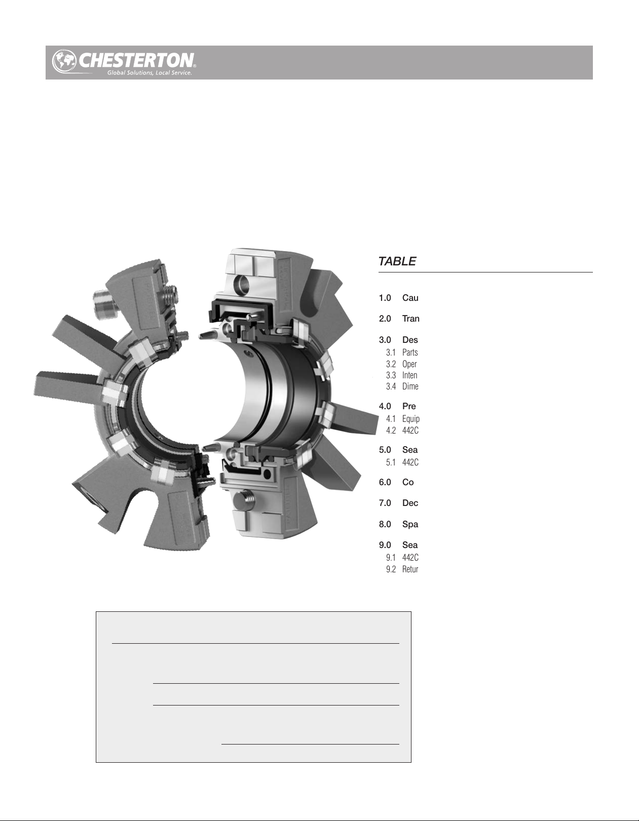
442C™ Cartridge
Split Mechanical Seal
Installation, Operation and Maintenance Instructions
TABLE OF CONTENTS
1.0 Cautions .............................................................................2
2.0 Transport and Storage .................................................2
3.0 Description ........................................................................2
3.1 Parts Identification .............................................................2 - 3
3.2 Operating Parameters .............................................................. 3
3.3 Intended Use ........................................................................... 3
3.4 Dimensional Data ...............................................................4 - 5
Seal Data Reference
(Insert seal and equipment data here for future reference)
ITEM #
4.0 Preparation for Installation .................................6 - 8
4.1 Equipment ............................................................................... 6
4.2 442C Cartridge Split Mechanical Seal.....................................7
5.0 Seal Installation ..................................................... 9 - 11
5.1 442C Installation Video ......................................................... 11
6.0 Commissioning/Equipment Start-up .................. 11
7.0 Decommissioning/Equipment Shut Down ....... 11
8.0 Spare Parts .................................................................... 11
9.0 Seal Maintenance and Repair ......................12 - 16
9.1 442C Seal Repair Instruction Video.......................................16
9.2 Returning Seals for Repair;
Hazard Communication Requirements .................................. 16
SEAL
(Example: 442C – 50 mm SSC/CB)
INSTALLATION D ATE
Page 2
1.0 CAUTIONS
G
P NPT
These instructions are general in nature. It is assumed
that the installer is familiar with seals and certainly with
the requirements of their plant for the successful use of
mechanical seals. If in doubt, get assistance from someone
in the plant who is familiar with seals or delay the installation
until a seal representative is available. All necessary auxiliary
arrangements for successful operation (heating, cooling,
flushing) as well as safety devices must be employed. These
decisions are to be made by the user. The decision to use this
seal or any other Chesterton seal in a particular service is the
customer’s responsibility.
2.0 TRANSPORT AND STORAGE
Transport and store seals in their original packaging.
Mechanical seals contain components that may be subject to
alteration and ageing. It is therefore important to observe the
following conditions for storage:
• Dust free environment
• Moderately ventilated at room temperature
• Avoid exposure to direct sunlight and heat
3.0 DESCRIPTION
Do not touch the mechanical seal for any reason while it is
operating. Lockout or uncouple the driver prior to personal
contact with the seal. Do not touch the mechanical seal
while it is in contact with hot or cold fluids. Ensure that all the
mechanical seal materials are compatible with the process
fluid. This will prevent possible personal injury.
• For elastomers, storage conditions should conform to
ISO 2230; particularly storage temperatures between 15°C
(59°F) and 25°C (77°F). If stored outside these ranges, the
seal assembly or spare parts should be unboxed in a clean
environment, with ambient temperature within the previously
stated ranges, and allowed to recover for at least 1 hour
prior to installation. Failure to follow this step can impact the
performance of the seal.
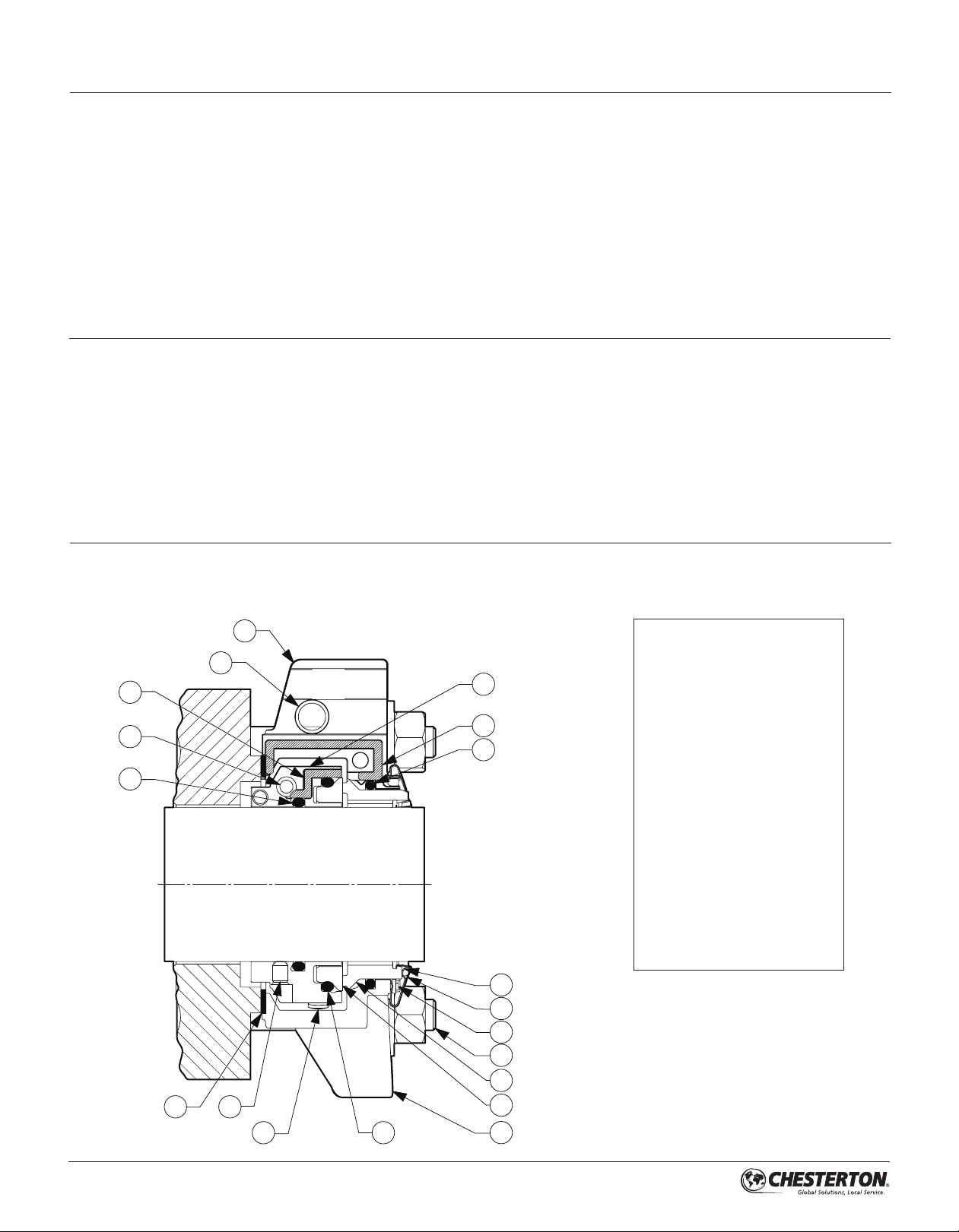
3.1 Parts Identification
Figure 1
10
3
2
4
11
19
16
15
KEY
1 – Rotary Holder
2 – Holder Cap Screw (X)
1
9
8
13
14
18
17
7
6
5
12
3 – Holder Gasket
4 – Shaft O-Ring
5 – Rotary O-Ring
6 – Rotary Face
7 – Stationary Face
8 – Stationary O-Ring
9 – Gland Gasket
10 – Gland Cap Screw (Y)
11 – Stuffing Box Gasket
12 – Bolt Tab
13 – Spring
14 – Spring Retainer
15 – Centering Button
16 – Gland
17 – Stuffing Box Bolts (Z)
18 – Spring Lifter
19 – Holder Set Screw (W)
2
Page 3
3.0 DESCRIPTION cont.
3.1 Parts Identification
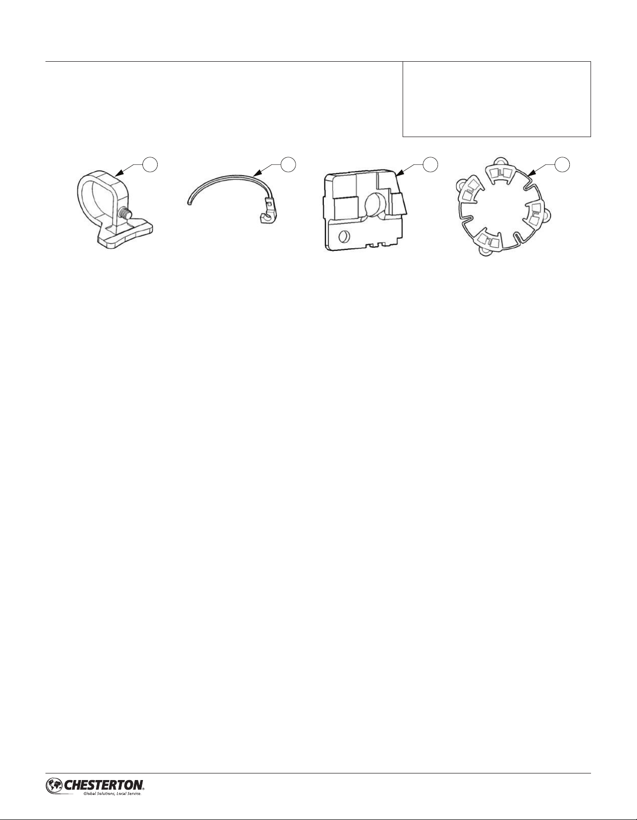
Figure 2
KEY
NOT SHOWN AS PART OF INSTALLED SEAL
20 – Rotary Holder Installation Spacer
21 – Rotary Holder Shipping Spacer
22 – Gland Shipping Spacer
23 – Gland Installation Tool
20
21
3.2 Operating Parameters*
Pressure Limits:
All 442 Seals can withstand operating pressures from full
vacuum (710 mm Hg /28") to the maximum pressures at the
conditions listed.
Small Sizes:
25 mm through 60 mm (1.000" through 2.500")
Reaction Bonded Silicon Carbide/Carbon – (3600 RPM)
up to 30 bar g/450 psig
Use 4 bolt mounting configuration for pressures above
20 bar g/300 psig
22
23
3.3 Intended Use
The mechanical seal is specifically designed for the intended
application and is to be operated within the operating
parameters as specified. For use beyond the intended
application and/or outside the operating parameters, consult
Chesterton to confirm the suitability of the mechanical seal
prior to putting the mechanical seal in operation.
Large Sizes:
65 mm through 120 mm (2.625" through 4.750")
Reaction Bonded Silicon Carbide/Carbon – (1750 RPM)
up to 18 bar g/250 psig
Use 4 bolt mounting configuration for pressures above
14 bar g/200 psig
Speed Limits:
To 20 m/s (4000 fpm)
Temperature Limits:
To 120°C (250°F)
* Consult Chesterton Mechanical Seal Application Engineering for higher
operating conditions.
3
Page 4
3.0 DESCRIPTION cont.
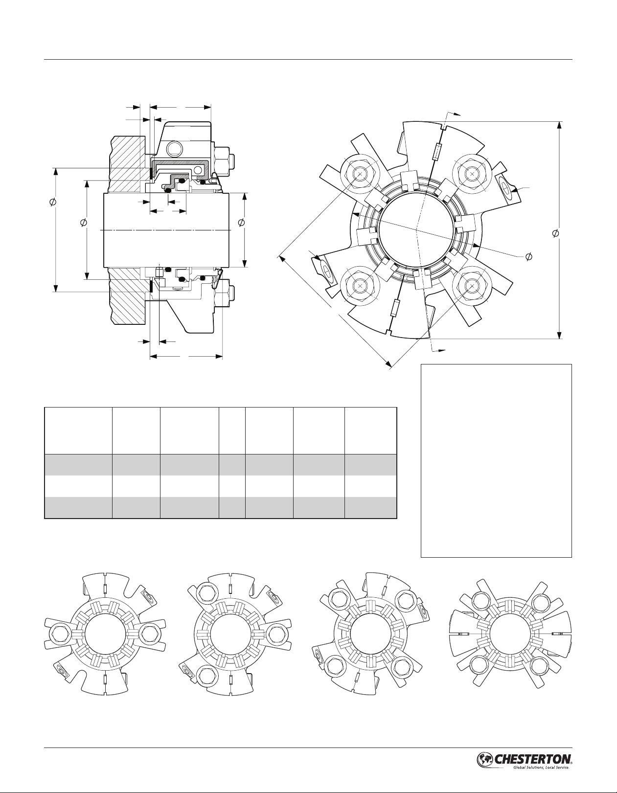
3.4 Dimensional Data (Drawings)
Figure 3
E
N
H
C
D
Q
M
A
P NPT
P NPT
B
L
G
R
F
Table 1 – Dimensional Data (Metric and Inch)
SHAFT SIZE
25 mm to 38 mm
(1.000" to 1.500")
40 mm to 60 mm
(1.625" to 2.500")
65 mm to 120 mm
(2.625" to 4.750")
M
HOLDER
INSIDE
DIAMETER
FROM BOX
24,4 mm
(0.96")
24,4 mm
(0.96")
27,1 mm
(1.07")
N
INSTALLATION
DIM
2,4 mm
(0.09")
2,4 mm
(0.09")
2,4 mm
(0.09")
P
NPT
SIZE
1/4"
3/8"
3/8"
Figure 4 – Mounting Configurations with Bolt Tabs
Q
SHAFT
O-Ring
FROM BOX
12,7 mm
(0.50")
12,7 mm
(0.50")
12,4 mm
(0.49")
R
SET SCREW
FROM BOX
5,8 mm
(0.23")
5,8 mm
(0.23")
5,8 mm
(0.23")
S
SLEEVE
LENGTH
FROM BOX
15,2 mm
(0.60")
15,2 mm
(0.60")
15,7 mm
(0.62")
KEY (chart)
A – Shaft Size
B – Max. Gland Dia.
C – Min./Max. Stuffing Box Dia.
D – Gland Length
E – Minimum Stuffing Box Depth
F – Outboard Seal Length
G – Min./Max. Bolt Circle by Bolt Size
H – Min. Stuffing Box Face
Outside Diameter
L – Gland Hub Outside Diameter
M – Holder End from Box
N – Installation Dimension
P – NPT Size
Q – Shaft O-Ring from Box
R – Set Screw from Box
S – Min. Sleeve Length from Box
2 BOLTS 3 BOLTS 4 BOLTS
44
Page 5
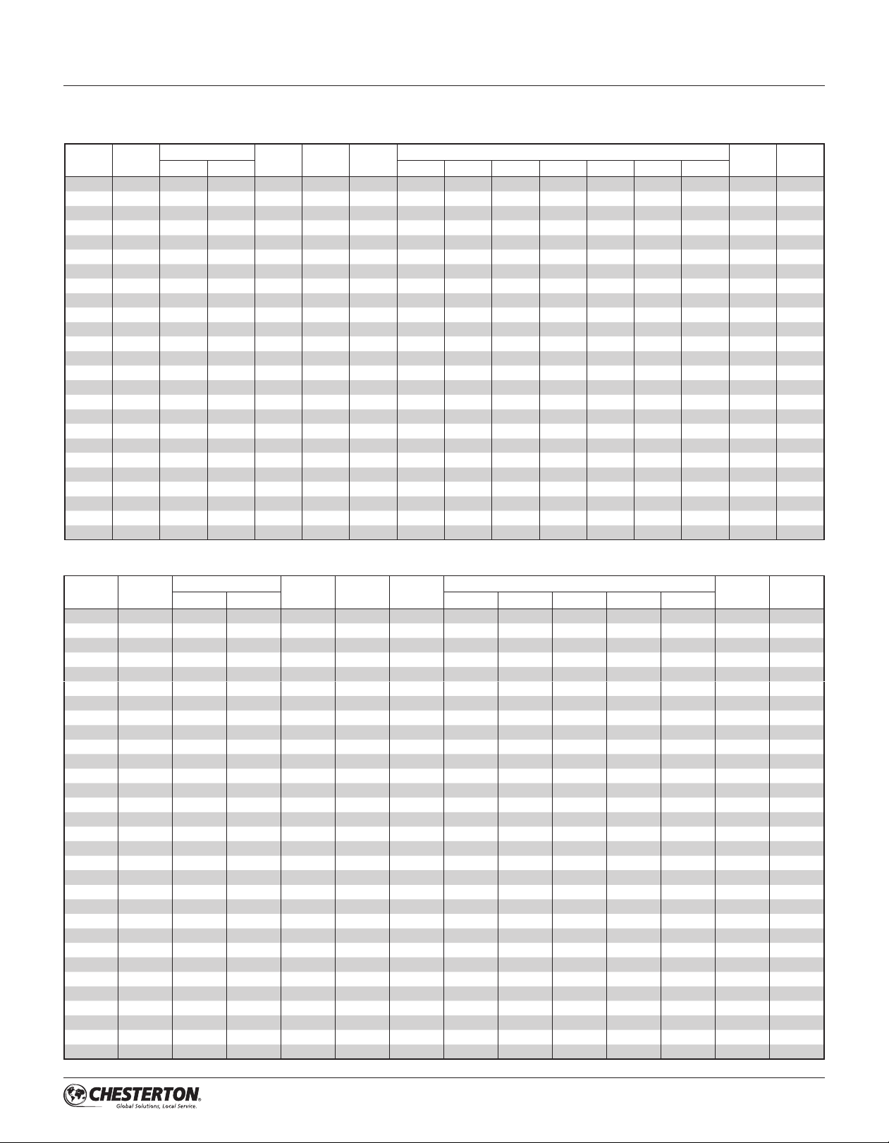
3.0 DESCRIPTION cont.
Table 2 – Dimensional Data
METRIC - Millimeters
A
25,0 125,5 47,2 53,3 40,1 4,3 47,8 79,8 81,8 83,8 85,8 87,8 - - 59,9 70,9
30,0 125,5 47,2 53,3 40,1 4,3 47,8 79,8 81,8 83,8 85,8 87,8 - - 59,9 70,9
32,0 125,5 47,2 53,3 40,1 4,3 47,8 79,8 81,8 83,8 85,8 87,8 - - 59,9 70,9
33,0 125,5 47,2 53,3 40,1 4,3 47,8 79,8 81,8 83,8 85,8 87,8 - - 59,9 70,9
35,0 127,4 49,3 60,5 40,1 4,3 47,8 81,8 83,8 85,8 87,8 89,8 - - 66,8 72,8
38,0 130,5 52,3 63,5 40,1 4,3 47,8 85,0 87,0 89,0 91,0 93,0 - - 69,9 76,0
40,0 133,6 55,6 66,8 40,1 4,3 47,8 87,4 89,4 91,4 93,4 95,4* - - 73,2 79,0
43,0 136,8 58,7 70,0 40,1 4,3 47,8 90,5 92,5 94,5 96,5 98,5* - - 76,2 82,0
45,0 136,8 58,7 70,0 40,1 4,3 47,8 90,5 92,5 94,5 96,5 98,5* - - 76,2 82,0
48,0 140,0 62,0 73,2 40,1 4,3 47,8 97,7 95,7 97,7 99,7 101,7* - - 79,5 85,2
50,0 143,2 65,0 76,2 40,1 4,3 47,8 98,4 100,4 102,4 104,4 106,4* - - 82,6 88,4
55,0 146,3 68,3 79,2 40,1 4,3 47,8 101,6 103,6 105,6 107,6 109,6 - - 85,9 91,5
60,0 152,6 74,7 85,6 40,1 4,3 47,8 107,8 109,8 111,8 113,8 115,8 - - 92,2 97,9
65,0 196,1 85,1 108,0 48,0 8,1 57,7 - - 140,6 142,6 144,6 146,6* 148,6* 120,7 126,6
70,0 196,1 85,1 108,0 48,0 8,1 57,7 - - 140,6 142,6 144,6 146,6* 148,6* 120,7 126,6
75,0 202,5 91,4 114,3 48,0 8,1 57,7 - - 146,2 148,2 150,2 152,2 154,2* 127,0 133,0
80,0 208,8 97,8 120,7 48,0 8,1 57,7 - - 154,8 156,8 158,8 160,8 162,8 133,4 139,3
85,0 215,2 104,1 127,0 48,0 8,1 57,7 - - 158,9 160,9 162,9 164,9 166,9 139,7 145,7
90,0 215,2 104,1 127,0 48,0 8,1 57,7 - - 158,9 160,9 162,9 164,9 166,9 139,7 145,7
95,0 221,5 110,5 133,4 48,0 8,1 57,7 - - 165,2 167,2 169,2 171,2 173,2 146,1 152,0
100,0 227,9 116,8 139,7 48,0 8,1 57,7 - - 171,6 173,6 175,6 177,6 179,6 152,4 158,4
105,0 234,2 123,2 146,1 48,0 8,1 57,7 - - 177,7 179,7 181,7 183,7 185,7 160,3 164,7
110,0 240,6 129,5 152,4 48,0 8,1 57,7 - - 184,3 186,3 188,3 190,3 192,3 165,1 171,1
115,0 240,6 129,5 152,4 48,0 8,1 57,7 - -
120,0 246,9 135,9 158,8 48,0 8,1 57,7 - - 190,6 192,6 194,6 196,6 198,6 171,5 177,4
B
MAX
C
MIN MAX 8 mm 10 mm 12 mm 14 mm 16 mm 18 mm 20 mm
D
E
MIN
F
184,3 186,3 188,3 190,3 192,3 165,1 171,1
G MIN
H
MINLMAX
INCH
A
1.000 4.94 1.86 2.10 1.58 0.17 1.88 3.20 3.33 3.45 3.58* - 2.35 2.79
1.125 4.94 1.86 2.10 1.58 0.17 1.88 3.20 3.33 3.45 3.58* - 2.35 2.79
1.250 4.94 1.86 2.10 1.58 0.17 1.88 3.20 3.33 3.45 3.58* - 2.35 2.79
1.375 5.02 1.94 2.38 1.58 0.17 1.88 3.28 3.40 3.53 3.66* - 2.63 2.87
1.500 5.14 2.06 2.50 1.58 0.17 1.88 3.40 3.53 3.65 3.78* - 2.75 2.99
1.625 5.26 2.19 2.63 1.58 0.17 1.88 3.50 3.63 3.81* 3.94* - 2.87 3.11
1.750 5.39 2.31 2.75 1.58 0.17 1.88 3.63 3.75 3.94* 4.06* - 3.00 3.23
1.875 5.51 2.44 2.88 1.58 0.17 1.88 3.75 3.88 4.06* 4.19* - 3.12 3.35
2.000 5.64 2.56 3.00 1.58 0.17 1.88 3.94 4.06 4.19* 4.31* - 3.25 3.48
2.125 5.76 2.69 3.12 1.58 0.17 1.88 4.06 4.19 4.31 4.44* - 3.37 3.60
2.250 5.88 2.81 3.25 1.58 0.17 1.88 4.19 4.31 4.44 4.56* - 3.50 3.73
2.375 6.01 2.94 3.37 1.58 0.17 1.88 4.31 4.43 4.56 4.69* - 3.62 3.85
2.500 6.13 3.06 3.75 1.58 0.17 1.88 4.57 4.70 4.82 4.95* - 4.00 4.23
2.625 7.72 3.35 4.25 1.89 0.32 2.27 5.44 5.56 5.69 5.81* 5.94* 4.75 4.99
2.750 7.72 3.35 4.25 1.89 0.32 2.27 5.44 5.56 5.69 5.81* 5.94* 4.75 4.99
2.875 7.97 3.60 4.50 1.89 0.32 2.27 5.66 5.78 5.91 6.03* 6.16* 5.00 5.24
3.000 7.97 3.60 4.50 1.89 0.32 2.27 5.66 5.78 5.91 6.03* 6.16* 5.00 5.24
3.125 8.22 3.85 4.75 1.89 0.32 2.27 6.00 6.12 6.25 6.37* 6.50* 5.25 5.48
3.250 8.22 3.85 4.75 1.89 0.32 2.27 6.00 6.12 6.25 6.37* 6.50* 5.25 5.48
3.375 8.47 4.10 5.00 1.89 0.32 2.27 6.16 6.28 6.41 6.53 6.66* 5.50 5.74
3.500 8.47 4.10 5.00 1.89 0.32 2.27 6.16 6.28 6.41 6.53 6.66* 5.50 5.74
3.625 8.72 4.35 5.25 1.89 0.32 2.27 6.41 6.53 6.66 6.78 6.91* 5.75 5.99
3.750 8.72 4.35 5.25 1.89 0.32 2.27 6.41 6.53 6.66 6.78 6.91* 5.75 5.99
3.875 8.97 4.60 5.50 1.89 0.32 2.27 6.66 6.78 6.91 7.03 7.16* 6.00 6.24
4.000 8.97 4.60 5.50 1.89 0.32 2.27 6.66 6.78 6.91 7.03 7.16* 6.00 6.24
4.125 9.22 4.85 5.75 1.89 0.32 2.27 6.90 7.02 7.15 7.27 7.40* 6.25 6.49
4.250 9.22 4.85 5.75 1.89 0.32 2.27 6.90 7.02 7.15 7.27 7.40* 6.25 6.49
4.375
4.500 9.47 5.10 6.00 1.89 0.32 2.27 7.16 7.28 7.41 7.53 7.66* 6.50 6.74
4.625 9.72 5.35 6.25 1.89 0.32 2.27 7.41 7.53 7.66 7.78 7.91* 6.75 6.99
4.750 9.72 5.35 6.25 1.89 0.32 2.27 7.41 7.53 7.66 7.78 7.91* 6.75 6.99
* Two bolts only usi ng bolt tabs
B
MAX
9.47 5.10 6.00 1.89 0.32 2.27 7.16 7.28 7.41 7.53 7.66* 6.50 6.74
C
MIN MAX 3/8" 1/2" 5/8" 3/4" 7/8"
D
E
MIN
F
G MIN
H
MIN
L
MAX
5
Page 6
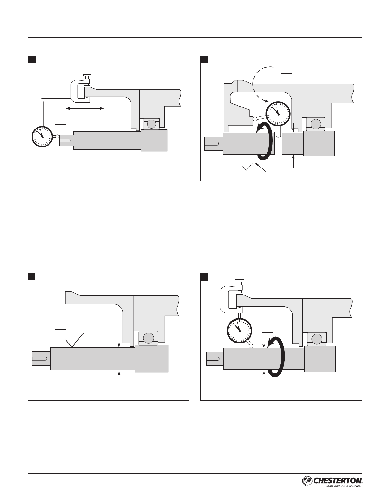
4.0 PREPARATION FOR INSTALLATION
4.1 Equipment
1
.005"
<
0,13 mm
2
125 µ"
3,2 µm
<
ø
200
ø
If practical, place the dial indicator tip on the end of the shaft
sleeve or on a step in the shaft to measure end play. Alternately
push and pull the shaft in the axial direction. If the bearings are
in good condition, end play should not exceed 0,13 mm (.005").
3
<
32 µ"
0,8 µm
R
a
If possible, attach a base dial indicator to the shaft and rotate
both the indicator and shaft slowly while reading the runout
of the stuffing box face. Misalignment of the stuffing box face
relative to the shaft should not exceed 0,005 mm TIR per mm
(.005 in per inch) of shaft diameter.
The stuffing box face must be flat and smooth enough to
seal the gland. Surface roughness should be 3,2 microns
(125 microinch) Ra maximum for gaskets and 0,8 micron (32
microinch) Ra for O-Rings. Steps between halves of split case
pumps should be machined flat. Make sure the stuffing box is
clean and clear along it’s entire length.
4
ø
<
1000
.002"
±
0,05 mm
ø
Remove all sharp corners, burrs, and scratches on the shaft,
especially in areas where the O-Ring will slide, and polish if
necessary to achieve a 0,8 micron (32 microinch) Ra finish.
Make sure the shaft or sleeve diameter is within 0,05 mm
(.002") of nominal.
ø
Use a dial indicator to measure the shaft runout in the
area where the seal will be installed. Runout should not
exceed 0,001 mm TIR per millimeter (.001 inch TIR per inch)
of shaft diameter.
66
Page 7

4.0 PREPARATION FOR INSTALLATION cont.
4.2 442C Cartridge Split Mechanical Seal
Review seal packaging ensuring no damage or shortage has
occurred to the contents.
Review the seal fit dimensions in Tables 1 and 2 to ensure the
equipment to be sealed has the required dimensions.
Record the seal Item Number and Name found on the label
for referencing when contacting AW Chesterton Application
Engineering.
Installation is straightforward, provided the parts are handled
and installed carefully. Make sure your hands are clean.
Prepare a clean work surface on which to place parts.
NOTES:
• The gland and rotary holder halves are matched pairs by
the same number stamped on each half; face halves are
matched pairs; mixing components from different seals will
result in seal failure.
• Greasy fingerprints on seal faces, dirt particles on the
faces seal faces/splits or misaligned face splits may cause
leakage. Do not bring the assembly halves together before
actual installation. Damage to the seal ring splits may occur.
REQUIRED FOR INSTALLATION
(Items are provided with seal):
• Hex key wrenches
• Grease
• Cleaning wipes
7
Page 8
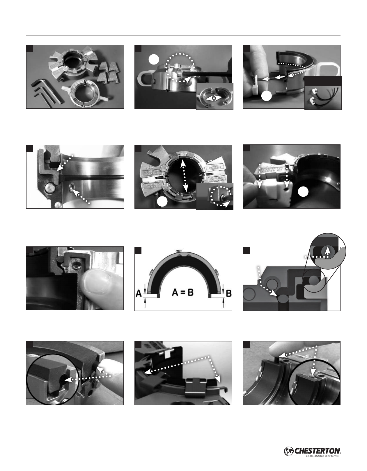
4.0 PREPARATION FOR INSTALLATION cont.
1
Remove seal from packaging and place on
clean work surface. Ensure installation spacers
are seated on outside diameter of rotary holder
halves. Important: DO NOT glue any O-Rings,
holder or gland half gaskets!
4
Holder Gasket
Set Screw
Ensure that the holder gaskets are lubricated and
seated in their grooves. Important: Set screws
protruding past the inside diameter may cause
the holder to deform resulting in shaft leakage
and/or damage to the rotary faces.
2 3
2X
Disengage rotary holder screws and separate
rotary holder halves.
5
2X
Disengage gland cap screws and separate gland
halves.
Shipping Spacer
Assembly
2X
Important! Remove entire shipping spacer
assembly from each holder half by pulling on tab;
retain for future use. Caution: Do not push on
the rotary faces. Re-install shipping spacers if
this occurs.
6
2X
Remove gland split shipping spacers from each
gland half.
7
Ensure that the gland gaskets are lubricated and
seated in their grooves.
10
To prevent seal leakage, ensure that the rotary
face O-Ring ends are flush with but not below
the face splits. Push on O-Ring ends if they
protrude past the face splits.
8
Ensure that the rotary holder shaft O-Ring is
properly seated in its groove with both ends
protruding evenly. Apply grease to shaft O-Ring
only where it contacts the shaft.
11
Spring Lifter
Ensure that gland spring lifter is extended
prior to star ting installation of gland assembly.
If spring lifter is not in its proper position, review
rebuild instructions.
9
Rotary holder
O-Ring detent
Shaft O-Ring
Ensure the rotary face O-Rings are positioned
in holder O-Ring detent. If rotary face O-Rings
are not in the holder detent, review rebuild
instructions.
12
To prevent seal leakage, ensure that the
stationary face O-Ring ends are flush with but
not below the stationary face splits. Carefully
push on O-Ring ends if they protrude past the
face splits. Preparation complete; go to Seal
Installation
8
Page 9
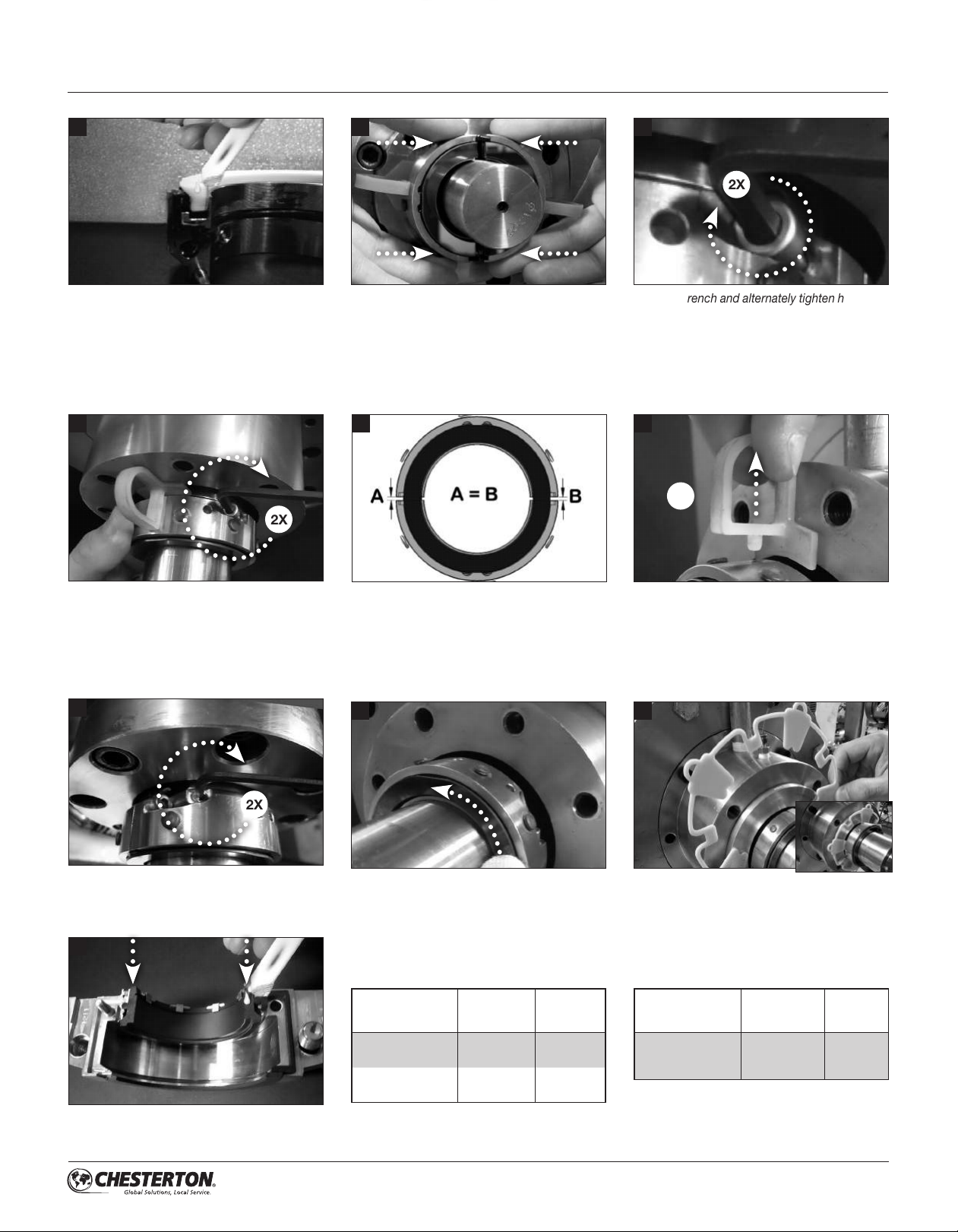
5.0 SEAL INSTALLATION
1
Equipment shaft should be cleaned and greased
prior to rotary holder installation. Apply supplied
grease only to face splits. Do not apply grease
to o-ring ends. Caution: Dirt particles on seal
face splits may cause leakage. The rotary holder
should not be rotated on the shaft during Steps
2 through 4 as it may lead to shaft leakage and/
or face damage.
4
2X
2
Bring rotary holder assembly halves together
over shaft, engaging the pins. Caution: DO NOT
use holder installation spacers as handles. Note:
If shaft cannot be rotated manually, the holder
split line should not align with the gland split line
(refer to steps 12 and 17).
5
3
2X
Use hex wrench and alternately tighten holder
cap screws to finger-tightness to allow holder
to slide along the shaft. Caution: Care should be
taken not to rotate the rotary holder on the shaft.
6
2X
Push holder assembly so that plastic installation
spacers contact the stuffing box. Face. Use hex
wrench and alternately tighten holder cap
screws (Refer to Table 3 - Holder Cap screw
Torque Values). Ensure gaps at holder splits are
equal on both sides (see Figure 5).
Caution: DO NOT push directly on seal face.
7
2X
Alternately tighten 2 holder set screws (1 per
holder half) (refer to Table 4 – Holder Set
Screw Torque Values).
10
Apply supplied grease only to face splits. Do
not apply grease to O-Ring ends. Caution: Dirt
particles on seal face splits may cause leakage.
Gaps at holder splits should be equal on both
sides.
8
Clean rotary face with supplied cleaning wipe,
ensuring there is no debris at splits. Caution: Do
not push on seal face - it may cause the seal face
to misalign resulting in seal leakage.
Table 3
Holder Cap Screw Torque Values
SEAL SIZE
SCREW* (X)
25 mm to 60 mm
(1" to 2.5")
65 mm to 120 mm
(2.625" to 4.75")
* Recommended maximum
HOLDER
CAP
4,8 Nm
(43 in-lbf)
12,4 Nm
(110 in-lbf)
HEX
WRENCH
SIZE
5/32
3/16
Remove installation spacers; retain for future
use.
9
Install gland installation tool between holder
assembly and stuffing box face.
Table 4
Holder Set Screw Torque Values
SEAL SIZE
25 mm to 120 mm
(1" to 4.75")
* Recommended maximum
SET SCREW*
HOLDER
(W)
4,3 Nm
(38 in-lbf)
HEX
WRENCH
SIZE
1/8
9
Page 10
5.0 SEAL INSTALLATION cont.
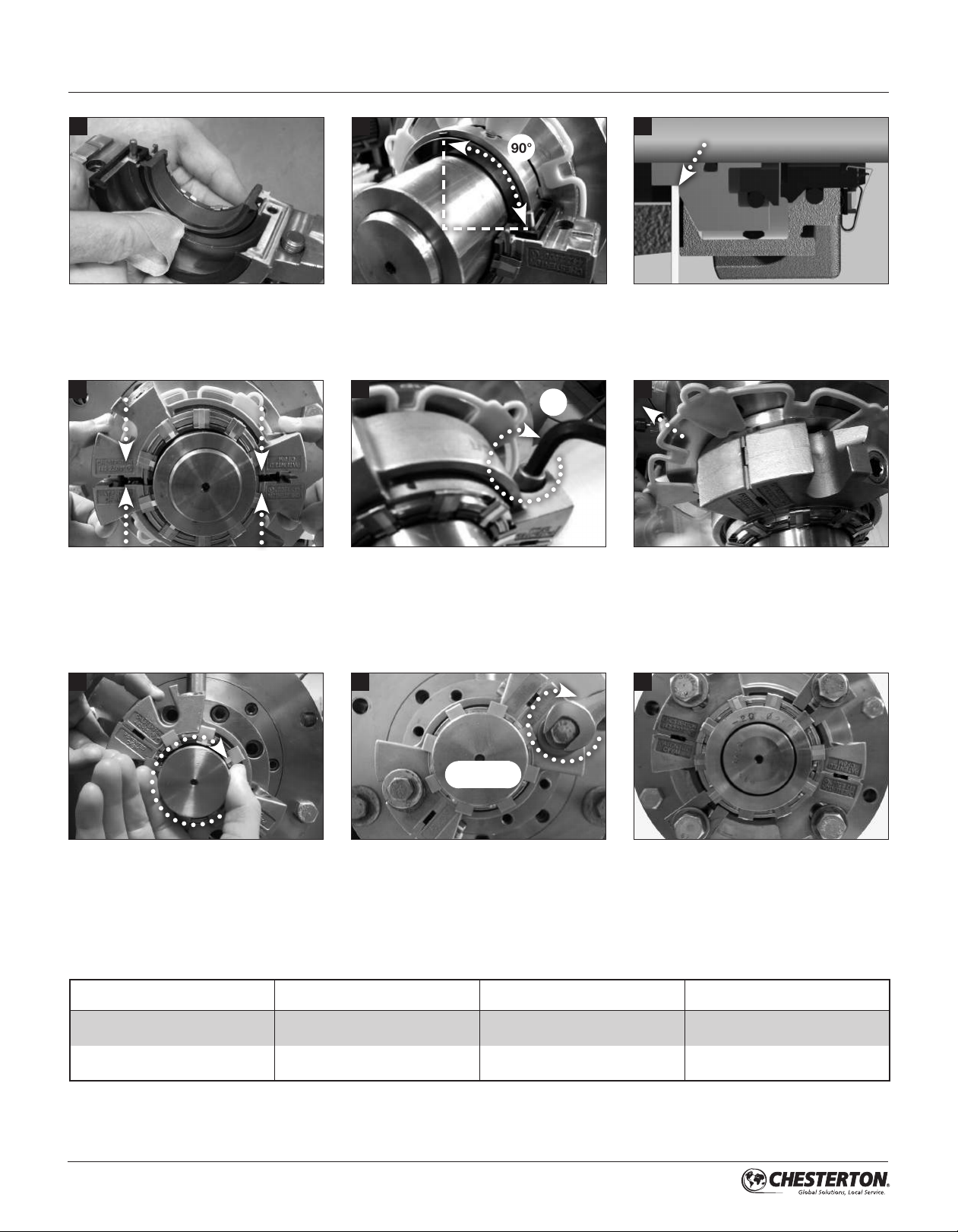
11
Clean stationary face with cleaning wipe,
ensuring that there is no debris at splits.
Bring the second gland half squarely into
position against the gland installation tool,
ensuring the pins and gland bolts are engaged.
12
90°
Position the gland splits approximately 90
degrees from the rotar y holder splits.
132X15
2X
Alternately tighten gland cap screws to specified
torque (refer to Table 5 – Gland Cap Screw and
Stuffing Box Bolt Torque Values). Note: The
spring lifter will automatically move into its final
position once the gland cap screws are tightened.
13
Installation Tool
Bring the first gland half squarely into position by
sliding the gland gasket face against the gland
installation tool, ensuring the stationary face
does not make contact with the rotary face.
1614
Carefully remove the gland installation tool,
taking care not to dislodge the gland stuffing
box gasket. Retain the gland installation tool for
future use.
18
2X or 4X
If possible rotate gland together with shaft when
aligning gland bolt slots with the stuffing box bolt
holes (refer to step 12 ).
Install and alternately tighten stuffing box
bolts to recommended torque (refer to
Table 5 – Gland Cap Screw and Stuffing Box
Bolt Torque Values) .
Table 5 – Gland Cap Screws and Stuffing Box Bolt Torque Values
SEAL SIZE
25 mm to 60 mm
(1" to 2.5")
65 mm to 120 mm
(2.625" to 4.75")
* Recommended maximum
** Typical Values : Torque necessary to seat stuffing box gasket varies with application.
GLAND
CAP SCREWS* (Y)
14-20 Nm
(125 – 175 in-lbf)
17-23 Nm
(150 – 200 in-lbf)
HEX WRENCH
SIZE
5/16
3/8
1917
Seal installation complete (refer to EQUIPMENT
STARTUP) . Note: Four bolt configuration
is shown. (refer to Figure 4 - Mounting
Configurations for other bolt quantities).
STUFFING BOX
BOLTS** (Z)
13,5-27 Nm
(15 – 20 ft-lbf)
27-34 Nm
(20 – 25 ft-lbf)
10
Page 11

5.0 SEAL INSTALLATION cont.
5.1 442C INSTALLATION VIDEO
To view an instructional installation video, please scan the
QR Code with your mobile device or go to our web page
at www.chesterton.com/442C_Videos and click on the
desired video.
6.0 COMMISSIONING / EQUIPMENT START-UP
1. Rotate the shaft by hand, if possible, to ensure no metal-to-
metal contact within the seal. A slight drag may be found
due to the seal faces and the centering buttons but the shaft
should rotate freely.
2. Attach appropriate plumbing/environmental controls to
the seal. Take all necessary precautions and follow normal
safety procedures before starting the equipment.
3. Depending on how carefully the seal components were
handled during installation, split seals may drip on startup.
For example, greasy fingerprints on the faces or misaligned
face splits may cause leakage. This type of leakage usually
decreases and stops over a period of time. If the leakage
remains steady, check O-Rings and gaskets for proper
installation and check the faces for chips, scratches and
proper alignment.
Please Contact Chesterton Mechanical Seal Application Engineering for
assistance regarding split seals.
7.0 DECOMMISSIONING / EQUIPMENT SHUT DOWN
Ensure that the equipment is electrically isolated. If the
equipment has been used on toxic or hazardous fluids, ensure
that the equipment is correctly decontaminated and made safe
prior to commencing work. Ensure that the pump is isolated
and check that the stuffing box is drained from any fluid and
pressure is fully released. Disassemble the 442C split seal and
remove from equipment in the reverse order from installation
instructions. Incase of disposal, ensure the local regulations
and requirements for disposal or recycling of the different
components in the seal are adhered to.
8.0 SPARE PARTS
Use only Chesterton original spare parts. Use of non-original
spare parts represents risk of failure, danger to persons/
equipment and voids the product warranty.
Spare Parts Kit can be purchased from Chesterton,
referencing the recorded seal data from cover page.
11
Page 12
9.0 SEAL MAINTENANCE AND REPAIR
A correctly installed and operated mechanical seal requires little
maintenance. It is recommended to periodically check the seal for
leakage. Wearing components of a mechanical seal such as seal
faces, O-Ring, etc., require replacement over time. While a seal is
installed and operating, maintenance is not possible. Therefore it
is recommended that a spare seal unit or a spare parts kit be held
in stock to allow quick repair.
1. Only the gland and rotary holder are reused. Caution: The
gland, rotary holder, face halves and O-Rings are matched
pairs; do not mix halves from different seals since this will cause
seal failure.
2. The following items, in addition to wrenches, grease and
cleaning wipes, will be required for rebuild:
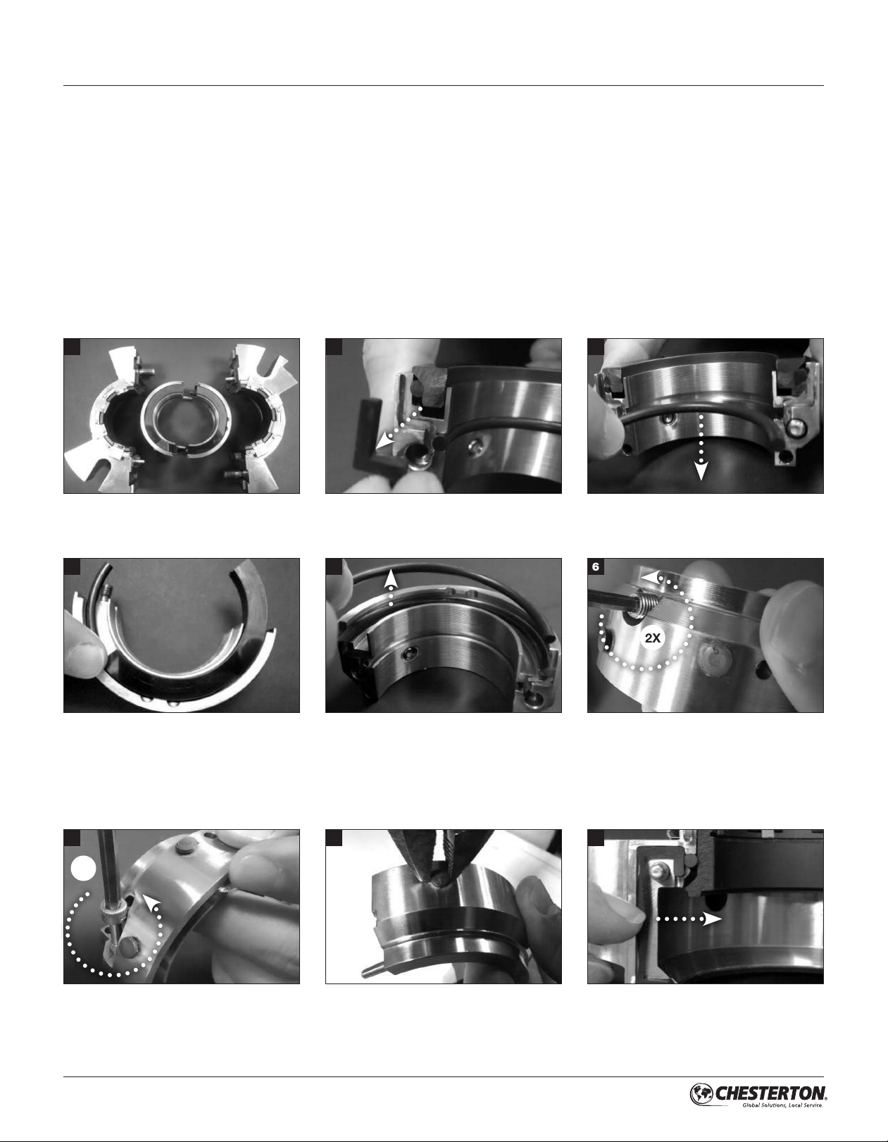
1
Prepare a clean work surface for seal
disassembly and rebuild.
2
Remove used rotary holder gaskets.
• Small pliers (remove centering buttons)
• Small, flat-head screwdriver (set spring lifter location)
• Plastic tipped mallet or hammer (replace
centering buttons)
• Cleaning solvent (clean elastomer/gasket surfaces)
3. Note the condition of the parts, including elastomer surfaces
and gland springs. Analyze the cause of failure and correct the
problem, if possible, before reinstalling the seal.
4. Clean all elastomer and gasket surfaces with
cleaning solvent.
3
Remove used shaft O-Ring halves.
4
Remove used rotary face halves by pushing on
end of face and sliding out of rotary holder half.
7
2X
5
Remove used rotary face O-Ring halves.
8
6
2X
Remove used holder set screws (2 places) from
rotary holder.
9
Remove used holder cap screws from holder
halves.
12
Remove used centering buttons from outside
diameter of rotary holder.
Remove used gland gaskets from gland grooves.
Page 13
9.0 SEAL MAINTENANCE AND REPAIR cont.
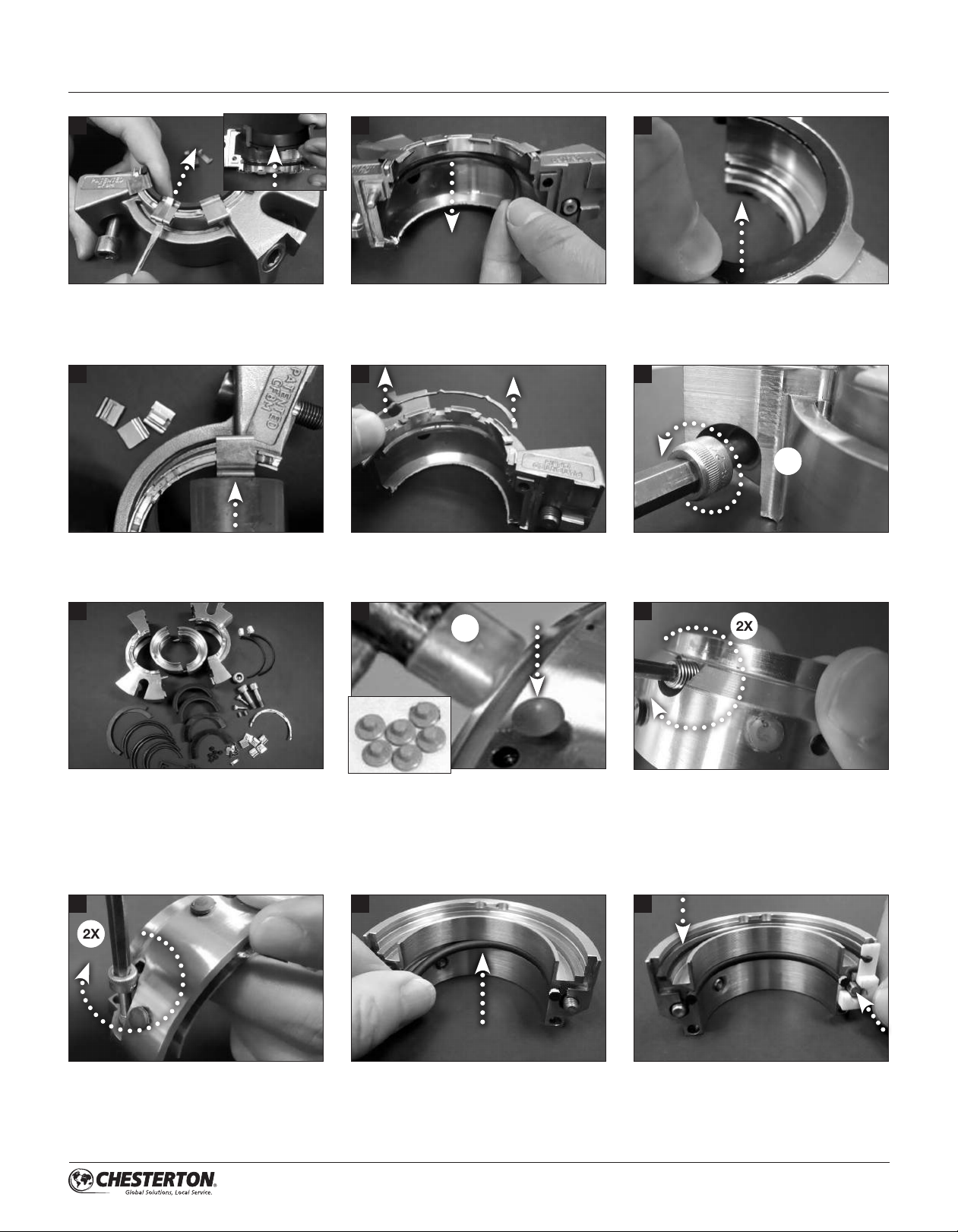
10
Remove used spring retainers from gland
halves. Note: When last retainer is removed the
stationary seal ring can be removed
13
Remove used springs from gland halves by
tapping them from the gland half inside diameter
with a small hammer
11
Remove used stationary face O-Ring.
14
Remove spring lifter halves from gland halves.
12
Remove used stuffing box gasket from gland
recess and all adhesive residue with cleaning
solvent.
15
2X2X
Remove used gland cap screws.
16
Remove all spare parts kit components from
packaging and place on the clean work surface.
19
2X2X
17
2X6X
Install new centering buttons on outside
diameter of rotary holder. Important: Make sure
buttons are fully seated without deforming the
exposed heads
20
18
2X
Lubricate threads with a recommended antiseize compound and install new holder set
screws (2 places) in rotary holder. Important:
Prior to installing the rotar y holder on the shaft/
sleeve, check to ensure the holder set screws are
not protruding beyond the inside diameter of the
rotary holder.
21
Lubricate threads with a recommended anti
seize compound and install holder cap screws in
rotary holder half.
Apply a thin film of grease and install shaft
O-Ring halves in rotary holder halves. O-Rings
must protrude evenly from both holder half ends.
(Refer to step 9 on page 8).
Install rotary holder shipping spacers in rotary
holder halves to hold the rotar y face O-Ring in
place.
13
Page 14
9.0 SEAL MAINTENANCE AND REPAIR cont.
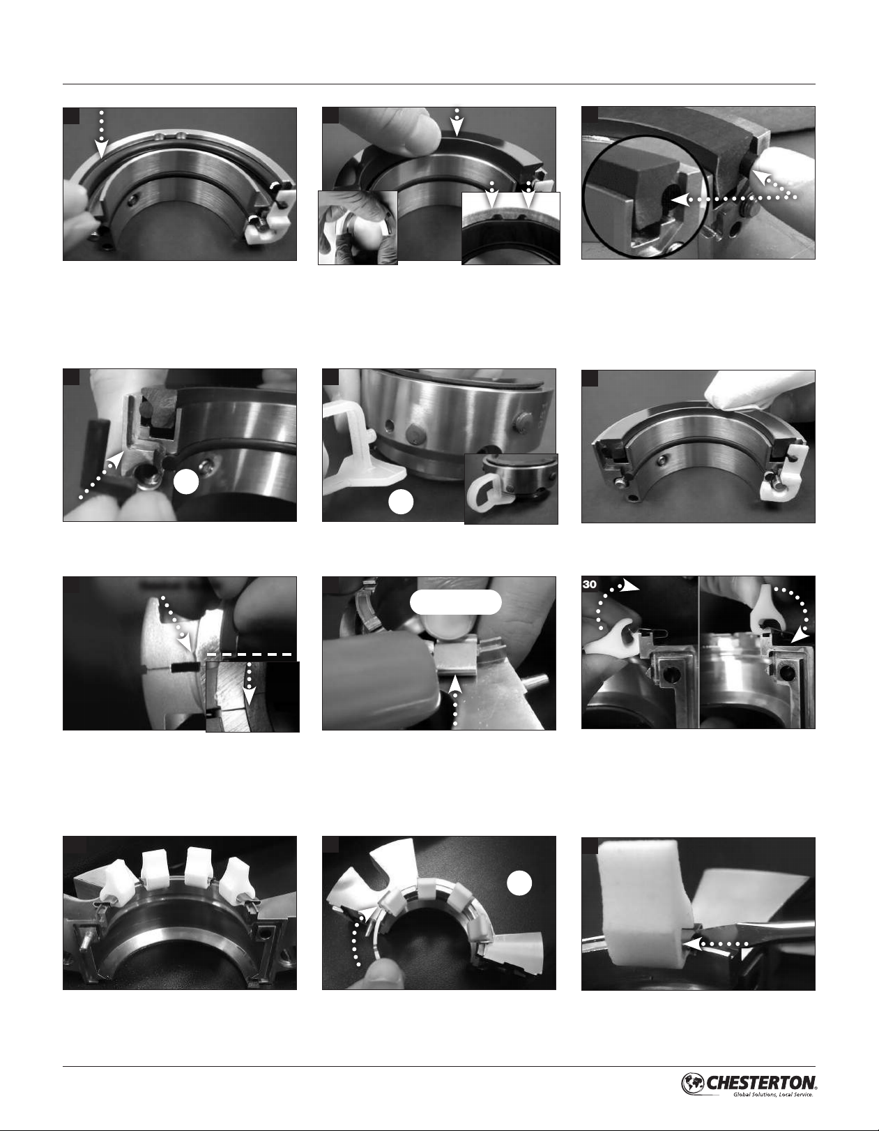
22
Apply a thin film of grease and install rotary face
O-Ring halves in rotary holder halves.
25
2X2X
23
Install rotary face halves in rotary holder halves.
Important: Manually press to seat the rotary
face in the holder halves while keeping pressure
on the plastic spacer and protruding O-ring to
ensure the O-ring position is maintained.
Align flat on outside diameter of rotary face with
flat on inside diameter surface of rotary holder.
26
2X
24
Ensure that the rotary face O-Ring ends are
flush, not below, with the face splits. Push on
O-Ring ends if they protrude past the face splits.
27
Apply a thin film of grease and install holder half
gaskets (1 per holder half).
28
Gasket Guide
Bring gland halves together. After peeling off
protective backing, seat one gasket half in the
gland recess ensuring that cut end aligns with
gasket guide. Seat second gasket half into gland
recess, ensuring that it butts up to cut ends of
first half.
30a
Install installation spacers on outside diameter of
holder halves.
29
6X, 8X or 10X
Install springs into spring slots on gland. Use a
plastic tipped mallet to ensure springs are seated
into place.
31
2X
Clean rotary face halves with cleaning wipe.
30
Install spring lifter clips in gland halves.
32
Spring lifter clips installed in gland halves.
14
Install spring lifter in gland halves such that
leading end is exposed beyond last spring.
Important: Bent TAB on spring lifter must be
installed on the recessed side of the gland.
Set spring lifter location using a flat head
screwdriver. Important: End of spring lifter must
be aligned with edge of the end spring. Remove
all clips and retain for re-setting lifter location.
Page 15
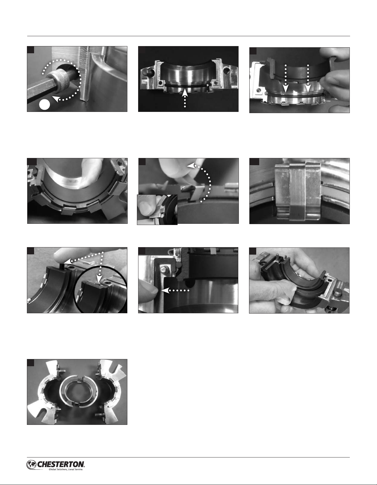
9.0 SEAL MAINTENANCE AND REPAIR cont.
33
2X
2X
2X2X
Install new gland cap screws in gland halves.
Note: Gland cap screws are installed in one end
of each gland half, in the ends away from the
mounting bolt slot.
35a
34
Apply a thin film of grease to the stationary face
O-Ring halves and install in gland halves; Ensure
that O-Ring splits are protruding evenly on both
sides.
36
35
Install stationary face halves into gland halves.
36a
Stationary face half installed in gland half.
Important: Ensure that O-Ring splits are still
protruding evenly at both sides.
37
Ensure that the stationar y face O-Ring ends
are flush with and not below the stationary face
splits. Push on O-Ring ends if they protrude past
the stationary face splits.
40
Install spring retainers in gland halves, holding
the stationary seal ring half in the gland.
38
Apply a thin film of grease to gland gaskets and
install in grooves of gland halves. Note: Gland
gaskets must be installed on gland end where
stuffing box face gasket protrudes.
Spring retainer installed.
39
Clean stationary face halves with cleaning wipe
to ensure there is no debris on face and at splits.
Seal components are ready for installation.
Proceed to Seal Installation Instructions.
15
Page 16
9.0 SEAL MAINTENANCE AND REPAIR cont.
9.1 442C SEAL REPAIR INSTRUCTION VIDEO
To view an instructional video on how to repair the 442C,
please scan the QR Code with your mobile device or go to our
web page at www.chesterton.com/442C_Videos and click
on the desired video.
9.2 RETURNING SEALS FOR REPAIR AND
HAZARD COMMUNICATION REQUIREMENTS
Any mechanical seal returned to Chesterton that has
been in operation, must comply with our Hazard
Communication requirements. Please scan the QR
Code with your mobile device or go to our web page at
www.chesterton.com/Mechanical_Seal_Returns to
obtain information required for returning seals for repair
or seal analysis.
860 Salem Street
Groveland, MA 01834 USA
Telephone: 781- 438-7000 Fax: 978- 469-6528
www.chesterton.com
© 2019 A.W. Chesterton Company.
® Registered trademark owned by A.W. Chesterton Company
in USA and other countries.
DISTRIBUTED BY:
FORM NO. EN14068 REV 8 01/19
Chesterton ISO certificates available on www.chesterton.com/corporate/iso
 Loading...