

Page 1
INSTALLATION, OPERATION and
MAINTENANCE INSTRUCTIONS
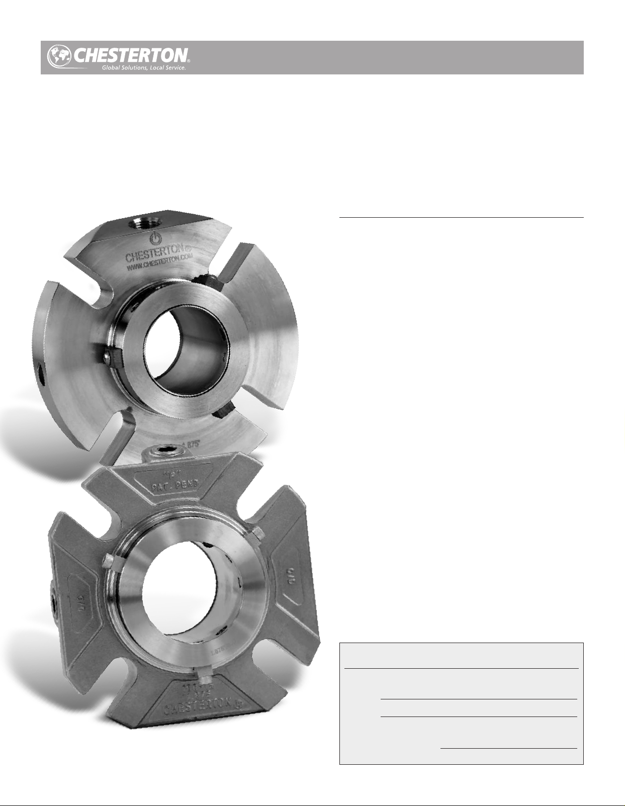
180 & 180H™
Cartridge Single Seal
Installation, Operation and Maintenance Instructions
TABLE OF CONTENTS
1.0 Cautions ................................................................................... 2
2.0 Transport and Storage .............................................................. 2
3.0 Description ..........................................................................2 - 8
3.1 Parts Identification .................................................................2 - 3
3.1.1 Seal Sizes 25 mm to 43 mm (1.000" to 1.625") ............................. 2
3.1.2 Seal Sizes 1.125" & 1.375" OVERSIZE Gland .................................3
3.1.3 Seal Sizes 45 mm to 120 mm (1.750" to 4.750") ........................... 3
3.2 Operating Parameters ................................................................. 4
3.3 Intended Use .............................................................................. 4
3.4 Dimensional Data ..................................................................5 - 8
3.4.1 Seal Sizes 25 mm to 43 mm (1.000" to 1.625") ............................. 5
3.4.2 Seal Sizes 1.125" & 1.375" OVERSIZE Gland .................................6
3.4.3 Seal Sizes 45 mm to 120 mm (1.750" to 4.750") ........................6-7
3.4.4 Seal Sizes 1.750" to 4.750" OVERSIZE Gland ................................. 8
4.0 Preparation for Installation....................................................... 9
4.1 Equipment ................................................................................. 9
4.2 Mechanical Seal ......................................................................... 9
5.0 Seal Installation ..................................................................... 10
6.0 Commissioning/Equipment Start-up ...................................... 11
7.0 Decommissioning/Equipment Shut Down .............................. 11
8.0 Spare Parts ............................................................................ 11
9.0 Seal Maintenance and Repair .........................................12 - 17
9.1 Seal Maintenance ..............................................................12 - 17
9.1.1 25 mm to 43 mm (1.000" to 1.625") Standard Seal Assembly .12-13
9.1.2 1.125" & 1.375" OVERSIZE Gland Seal Assembly ....................14-15
9.1.3 45 mm to 120 mm (1.750" to 4.750" ) Seal Assembly .............16-17
9.2 Returning Seals for Repair ........................................................ 17
10.0 180H Seal ............................................................................... 18
10.1 180H Seal Overview ................................................................. 18
10.2 180H Environmental Control Considerations ........................18 - 19
10.2.1 180H Flush Port Connection ....................................................20
Product may be provided with either cast or machined gland
Seal Data Reference
(From Box Label)
ITEM #
SEAL
(Example: 180H -15 SSC/CB)
IN S TA LL AT I O N DATE
Page 2
1.0 CAUTIONS
These instructions are general in nature. It is assumed
that the installer is familiar with seals and certainly with
the requirements of their plant for the successful use of
mechanical seals. If in doubt, get assistance from someone
in the plant who is familiar with seals or delay the installation
until a seal representative is available. All necessary auxiliary
Do not touch the mechanical seal for any reason while it is
operating. Lockout or uncouple the driver prior to personal
contact with the seal. Do not touch the mechanical seal
while it is in contact with hot or cold fluids. Ensure that all the
mechanical seal materials are compatible with the process
fluid. This will prevent possible personal injury.
arrangements for successful operation (heating, cooling,
flushing) as well as safety devices must be employed. These
decisions are to be made by the user. The decision to use this
seal or any other Chesterton seal in a particular service is the
customer’s responsibility.
2.0 TRANSPORT AND STORAGE
Transport and store seals in their original packaging.
Mechanical seals contain components that may be subject to
alteration and ageing. It is therefore important to observe the
following conditions for storage:
• Dust free environment
• Moderately ventilated at room temperature
• Avoid exposure to direct sunlight and heat
• For elastomers, storage conditions according to ISO 2230
should be observed.
3.0 DESCRIPTION
3.1 Parts Identification
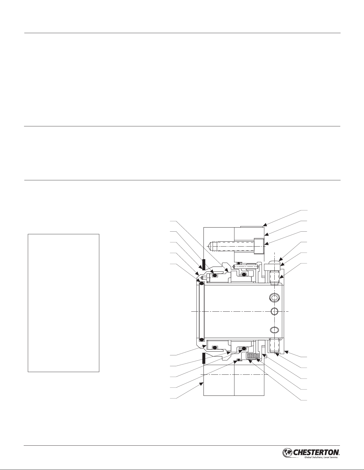
3.1.1 Seal Sizes: 25 mm to 43 mm (1.000" to 1.625") – Figure 1
5
21
13
KEY
1 - Sleeve Assembly
2 - Shaft O-Ring
3 - Rotary Gasket
4 - Rotary O-Ring
5 - Rotary Seal Ring
6 - Gland Gasket
7 - Stationary Seal Ring
8 - Gland O-Ring
9 - Pusher
10 - Spring
11 - Bushing
12 - Inner Gland Assembly
13 - Outer Gland
14 - Centering Clip Screw
15 - Centering Clip
16 - Lock Ring
17 - Stationary O-Ring
18 - Dog Pt Set Screw
19 - Cup Pt Set Screw
20 - Socket Head Cap Screw
21 - Caplug
17
12
4
6
1
2
3
7
8
20
14
15
18
16
19
11
10
9
22
Page 3
3.0 DESCRIPTION (cont.)
3.1 Parts Identification
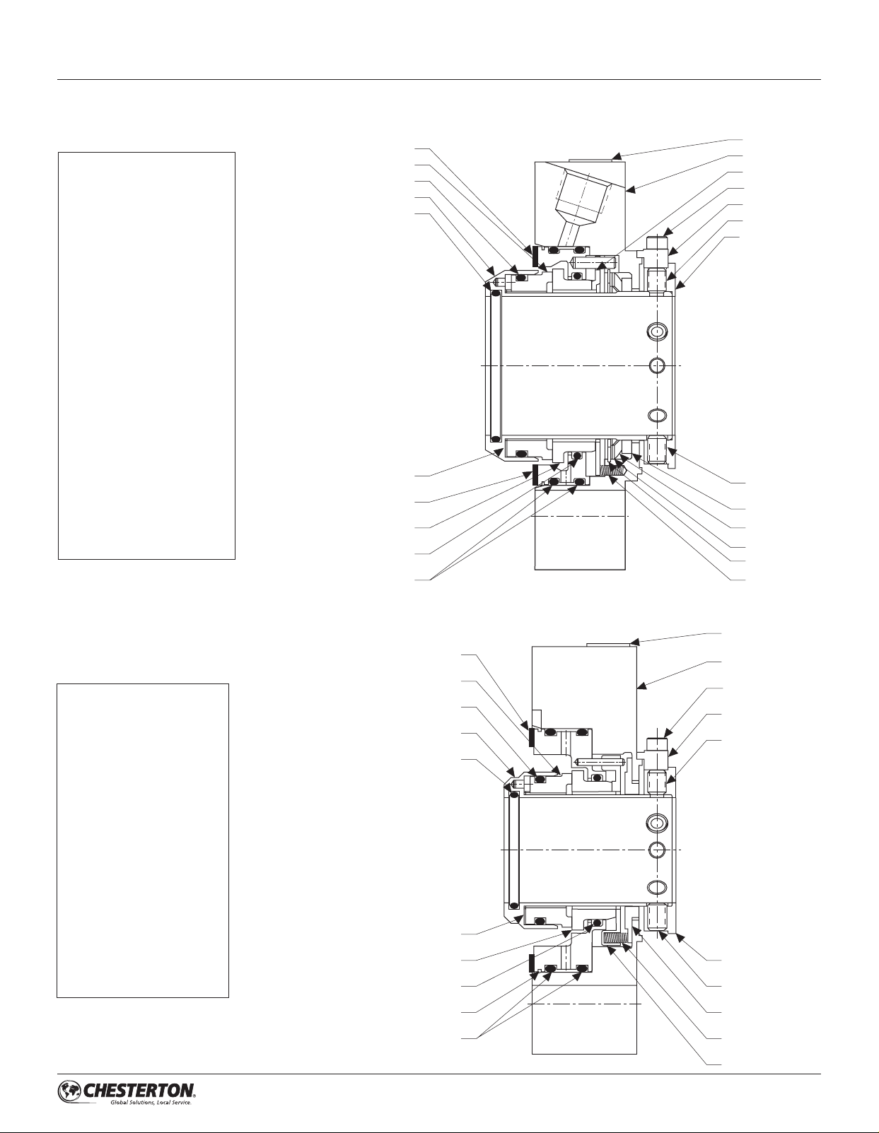
3.1.2 Seal Sizes: 1.125" & 1.375" OVERSIZE – Figure 2
6
KEY
1 - Sleeve Assembly
2 - Shaft O-Ring
3 - Rotary Gasket
4 - Rotary O-Ring
5 - Rotary Seal Ring
6 - Gland Gasket(s)**
7 - Stationary Seal Ring
8 - Adapter Assembly
9 - Stationary O-Ring
10 - Pusher Plate
11 - Spring
12 - Snap Ring
13 - Shim
14 - Wave Spring
15 - Throttle Bushing
16 - Gland
17 - Centering Clip Screw
18 - Centering Clip
19 - Lock Ring
20 - Adapter O-Ring(s)**
21 - Dog Pt Set Screw
22 - Cup Pt Set Screw
23 - Caplug
Optional
*
OVERSIZE design uses
**
1 O-Ring (20) and 2 gaskets (6)
*
*
*
*
5
4
1
2
3
8
7
9
20
23
16
10
17
18
21
19
22
15
14
13
12
11
3.1.3 Seal Sizes: 45 mm to 120 mm (1.750" to 4.750") – Figure 3
6
KEY
1 - Sleeve Assembly
2 - Shaft O-Ring
3 - Rotary Gasket
4 - Rotary O-Ring
5 - Rotary Seal Ring
6 - Gland Gasket
7 - Stationary Seal Ring
8 - Adapter Assembly
9 - Pusher
10 - Spring
11 - Bushing
12 - Gland
13 - Adapter O-Rings
14 - Centering Clip Screw
15 - Centering Clip
16 - Lock Ring
17 - Stationary O-Ring
18 - Dog Pt Set Screw
19 - Cup Pt Set Screw
20 - Caplug
5
4
1
2
3
7
17
8
20
12
14
15
18
16
19
11
13
10
9
33
Page 4

3.0 DESCRIPTION (cont.)
3.2 Operating Parameters*
Pressure Limits:
All 180 & 180H Seals can withstand operating pressures from
full vacuum (710 mm Hg/28") to the maximum pressures at the
conditions listed.
25 to 60 mm (1.000" to 2.500")
Up to 26 bar g (600 psig)*
65 to 120 mm (2.625" to 4.750")
20 bar g to 26 bar g (300 to 600 psig) *
* Seal pressure c apabilities are dependent on the fluid sealed, temperature, speed,
and seal face combinations.
Standard Materials**:
All Metal Parts: 316 SS / EN 1.4401
Springs: Alloy C276 / EN 2.4819
Rotary Face: Carbon; Silicon Carbide; Tungsten Carbide
Stationary Face: Silicon Carbide; Tungsten Carbide
Elastomers: FKM, FEPM or EPDM installed
** Other materials available upon request.
Speed Limits:
Up to 5000 fpm (25 m/s)
Temperature Limits:
Elastomers
To 150°C (300°F) EPDM
To 205°C (400°F) FEPM, FKM
To 260°C (500°F) FFKM
* Consult Chesterton Mechanical Seal Application Engineering for higher operating
conditions.
3.3 Intended Use
The mechanical seal is specifically designed for the intended
application and is to be operated within the operating
parameters as specified. For use beyond the intended
application and/or outside the operating parameters, consult
Chesterton Mechanical Seal Application Engineering to
confirm the suitability of the mechanical seal prior to putting
the mechanical seal in operation.
4
Page 5
3.0 DESCRIPTION (cont.)
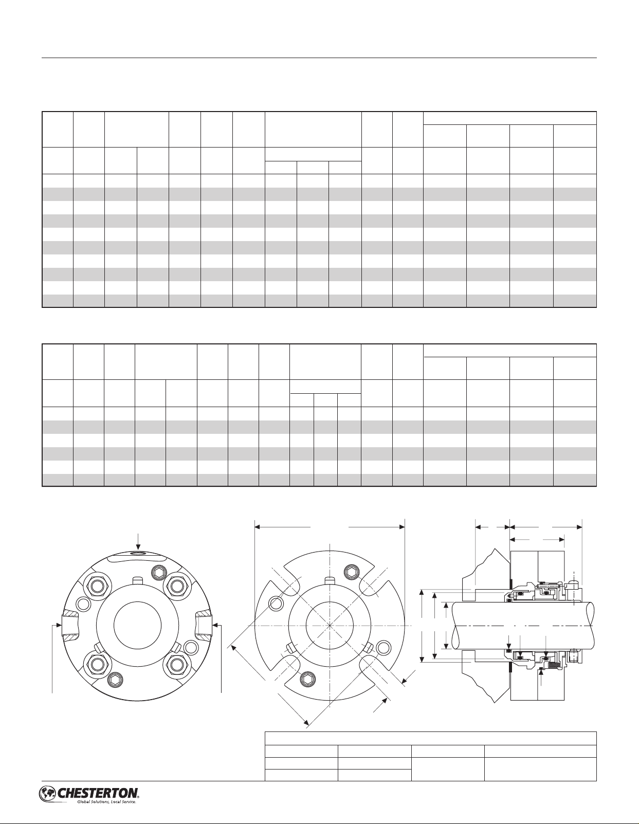
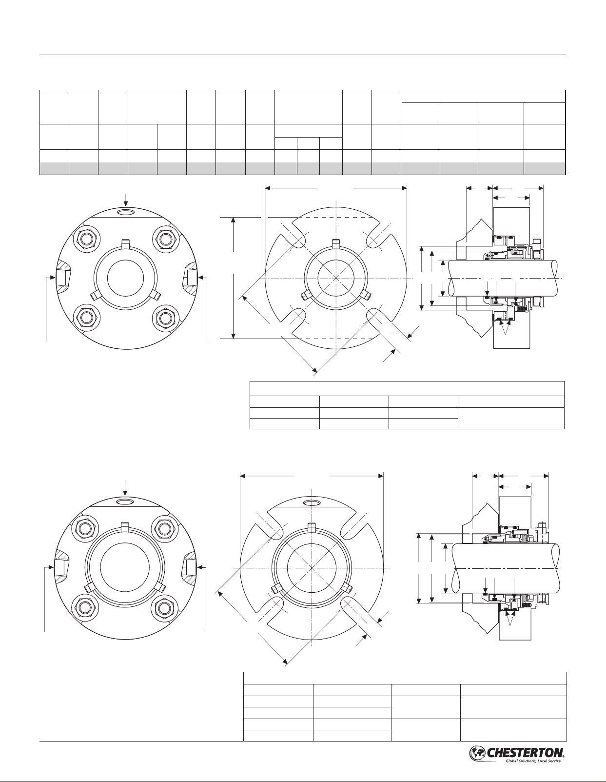
3.4.1 Dimensional Data - Seal Sizes: 25 mm to 43 mm (1.000" to 1.625")
METRIC - Millimeters
O-RINGS
SHAFT GLAND STUFFING BOX IB SEAL SB OB BOLT CIRCLE SLOT GLAND
SIZE OD BORE DIA DEPTH LENGTH BY BOLT SIZE WIDTH WIDTH SHAFT ROTARY
A B C C D E F G MIN H J V W X Y
MAX MIN MAX MAX MIN MAX 10 mm 12 mm 16 mm MAX
25 104 41 51 39 6 54 73 11 41 120 126 127 033
28 104 44 52 42 6 54 73 11 41 122 128 129 034
30 104 46 57 44 6 54 78 11 41 123 129 130 035
32 104 48 58 46 6 54 80 11 41 124 130 131 035
33 113 49 59 47 6 54 81 83 14 41 125 131 132 036
35 111 51 59 49 6 54 80 82* 14 41 126 132 133 036
38 114 54 61 52 6 54 85 87 14 41 128 134 135 037
40 127 56 68 54 6 54 90 92 13 41 129 135 136 038
42 127 58 66 56 6 54 88 90 13 41 130 136 137 039
43 127 59 69 57 6 54 91 93 13 41 131 137 138 039
Requires SHCS or D shaped washers.
*
INCH
O-RINGS
DASH SHAFT GLAND STUFFING BOX IB SEAL SB OB BOLT CIRCLE SLOT GLAND
NO. SIZE OD BORE DIA DEPTH LENGTH BY BOLT SIZE WIDTH WIDTH SHAFT ROTARY
A B C C D E F G MIN H J V W X Y
MAX MIN MAX MAX MIN MAX 3/8" 1/2" 5/8" MAX
-8 1.000 4.11 1.63 2.01 1.55 0.22 2.11 2.88 0.44 1.62 120 126 127 033
-9 1.125 4.11 1.75 2.04 1.67 0.22 2.11 2.88 0.44 1.62 122 128 129 034
-10 1.250 4.11 1.88 2.27 1.80 0.22 2.11 3.14 0.44 1.62 124 130 131 035
-11 1.375 4.36 2.00 2.33 1.92 0.22 2.11 3.13 3.25* 0.57 1.62 126 132 133 036
-12 1.500 4.49 2.13 2.44 2.05 0.22 2.11 3.33 3.45 0.57 1.62 128 134 135 037
-13 1.625 4.99 2.25 2.69 2.17 0.22 2.11 3.52 3.65 0.57 1.62 130 136 137 038
Requires SHCS or D shaped washers.
*
STATIONARY
STATIONARY
GLAND
GLAND
QUENCH/
DRAIN
FLUSH
QUENCH/
DRAIN
B MAX
E
MIN
G MIN
CDA
H
V W X
Seal Sizes 25 mm to 43 mm (1.000" to 1.625" ) - NPT SIZES
DASH NO. SHAFT SIZE FLUSH PORT QUENCH/DRAIN PORTS
-8 to -13 1.000" to 1.625"
– 25 mm to 43 mm
1/4 - 18 1/4 - 18
F
J
Y
5
Page 6
3.0 DESCRIPTION (cont.)
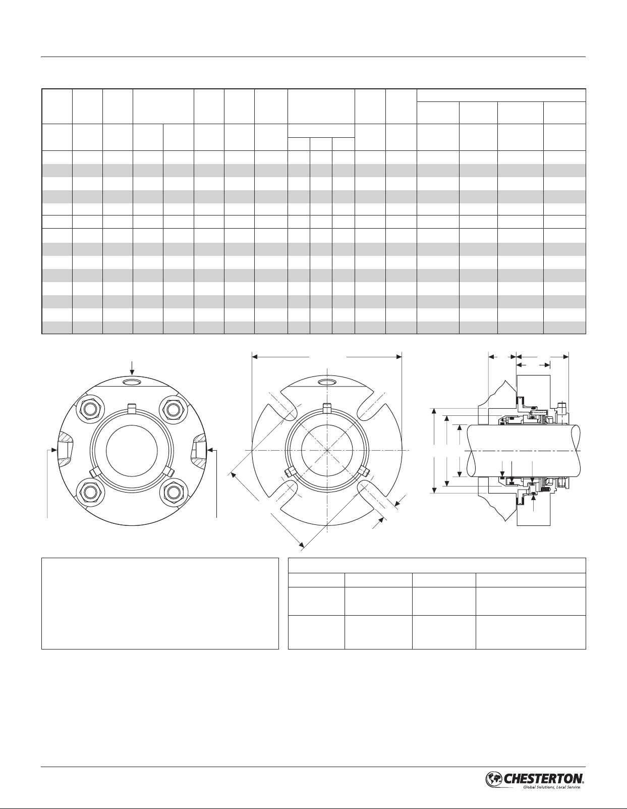
3.4.2 Dimensional Data - Seal Sizes: 1.125" & 1.375" with OVERSIZE Gland
O-RINGS
DASH SHAFT GLAND STUFFING BOX IB SEAL SB OB BOLT CIRCLE SLOT GLAND
NO. SIZE OD BORE DIA DEPTH
A B C C D E F G MIN H J V W X Y
MAX MIN MAX MAX MIN MAX 3/8" 1/2" 5/8" MAX
- 9 OS 1.125 4.48 2.50 2.75 1.82 0.40 1.93 3.71 0.44 1.44 122 128 129 150
-11 OS 1.375 5.40 2.68 3.00 2.07 0.40 1.93 4.03 0.44 1.44 126 132 133 151
LENGTH
BY BOLT SIZE WIDTH WIDTH SHAFT ROTARY
STATIONARY
ADAPTER
QUENCH/
DRAIN
FLUSH
QUENCH/
DRAIN
4.25
(
-11 ONLY
)
G MIN
B MAX
H
Seal Sizes: 1.125" & 1.375" OVERSIZE GLAND - NPT SIZES
DASH NO. SHAFT SIZE FLUSH PORT QUENCH/DRAIN PORTS
-9 OS 1.12 5 1/8 - 27
-11 OS 1.375 1/4 - 18
3.4.3 Dimensional Data - Seal Sizes: 45 mm to 120 mm (1.750" to 4.750")
E
MIN
A
DC
V
W
1/4 - 18
F
J
X
Y
QUENCH/
DRAIN
6
FLUSH
QUENCH/
DRAIN
G MIN
B MAX
A
DC
H
E
MIN
V
J
W
X
Y
Seal Sizes: 45 mm to 120 mm (1.750" to 4.750" ) - NPT SIZES
DASH NO. SHAFT SIZE FLUSH PORT QUENCH/DRAIN PORTS
-14 to -20 1.750" to 2.500"
– 45 mm to 60 mm"
-21 to -38 2.625" to 4.750"
– 65 mm to 120 mm
3/8 - 18 3/8 - 18
1/2 - 14 1/2 - 14
F
Page 7

3.0 DESCRIPTION (cont.)
METRIC (millimeters)
O-RINGS
SHAFT GLAND STUFFING BOX IB SEAL SB OB BOLT CIRCLE SLOT GLAND
SIZE OD BORE DIA DEPTH LENGTH BY BOLT SIZE WIDTH WIDTH SHAFT ROTARY STATIONARY ADAPTER
A B C C D E F G MIN H J V W X Y
MAX MIN MAX MAX MIN MAX 10 mm 12 mm 16 mm MAX
45 139 64 73 63 18 49 95 97 13 43 133 139 140 150
48 139 67 73 66 18 49 95* 97* 13 43 134 141 142 151
50 139 69 78 68 18 49 100 102 13 43 136 142 143 151
53 152 73 87 72 18 49 109 111 115 17 43 137 144 145 153
55 152 74 83 73 18 49 105 107 111 17 43 139 145 146 152
58 152 80 91 78 18 49 114 116 120 17 43 140 148 149 153
60 152 80 91 78 18 49 114 116 120 17 43 142 148 149 153
12 mm 16 mm 20 mm
65 164 92 103 90 22 64 127 131 17 45 231 235 236 242
70 196 96 111 93 22 64 137 141 17 45 232 236 237 245
75 202 102 119 100 22 64 143 147 17 45 234 238 239 247
80 203 106 122 103 22 64 150 154 17 45 236 239 240 248
85 211 111 128 109 22 64 152 156 161 20 45 237 241 242 250
90 214 116 132 113 22 64 160 164 168 20 45 239 242 243 251
95 221 121 137 119 22 64 161 165 170 20 45 240 244 245 253
100 228 127 144 125 22 64 168 172 177 20 45 242 246 247 255
110 237 137 154 134 22 64 178 182 186 20 45 245 249 250 258
120 266 146 164 144 22 64 187 191 195 20 45 248 252 253 259
Requires SHCS or D shaped washers.
*
INCH
O-RINGS
DASH SHAFT GLAND STUFFING BOX
NO. SIZE OD BORE DIA DEPTH LENGTH BY BOLT SIZE WIDTH WIDTH SHAFT ROTARY STATIONARY ADAPTER
A B C C D E F G MIN H J V W X Y
MAX MIN MAX MAX MIN MAX 3/8" 1/2" 5/8" MAX
-14 1.750 5.49 2.50 2.81 2.44 0.69 1.91 3.62 3.75* 0.57 1.27 132 138 139 150
-15 1.875 5.49 2.63 2.94 2.57 0.69 1.91 3.75 3.87* 0.57 1.27 134 140 141 151
-16 2.000 5.49 2.75 3.19 2.69 0.69 1.91 4.00 4.13 0.57 1.27 136 142 143 152
-17 2.125 5.99 2.88 3.44 2.82 0.69 1.91 4.25 4.38 4.50 0.69 1.27 138 144 145 153
-18 2.250 5.99 3.00 3.56 2.94 0.69 1.91 4.37 4.50 4.62 0.69 1.27 140 146 147 153
-19 2.375 5.99 3.13 3.59 3.07 0.69 1.91 4.43 4.56 4.68 0.69 1.27 142 148 149 153
-20 2.500 6.49 3.25 3.81 3.19 0.69 1.91 4.62 4.75 4.87 0.69 1.27 144 150 151 154
1/2" 5/8" 3/4"
-21 2.625 6.45 3.63 4.04 3.54 0.88 2.50 5.02 5.15 0.69 1.77 231 236 237 242
-22 2.750 7.70 3.75 4.38 3.67 0.88 2.50 5.42 5.55 0.69 1.77 232 236 237 245
-23 2.875 7.83 3.88 4.50 3.79 0.88 2.50 5.50 5.62 0.69 1.77 233 237 238 246
-24 3.000 7.94 4.00 4.69 3.92 0.88 2.50 5.65 5.77 0.69 1.77 234 238 239 247
-25 3.125 7.99 4.13 4.81 4.04 0.88 2.50 5.80 5.92 0.69 1.77 235 239 240 248
-26 3.250 8.19 4.25 4.94 4.17 0.88 2.50 5.93 6.05 0.69 1.77 236 240 241 249
-27 3.375 8.30 4.38 5.06 4.29 0.88 2.50 6.02 6.14 6.27 0.81 1.77 237 241 242 250
-28 3.500 8.44 4.50 5.19 4.42 0.88 2.50 6.18 6.31 6.43 0.81 1.77 238 242 243 251
-29 3.625 8.49 4.63 5.31 4.54 0.88 2.50 6.31 6.44 6.56 0.81 1.77 239 243 244 252
-30 3.750 8.71 4.75 5.39 4.67 0.88 2.50 6.38 6.51 6.63 0.81 1.77 240 244 245 253
-31 3.875 8.84 4.88 5.51 4.79 0.88 2.50 6.52 6.64 6.77 0.81 1.77 241 245 246 254
-32 4.000 8.96 5.00 5.69 4.92 0.88 2.50 6.66 6.78 6.91 0.81 1.77 242 246 247 255
-33 4.125 8.99 5.13 5.81 5.04 0.88 2.50 6.79 6.90 7.03 0.81 1.77 243 247 248 256
-34 4.250 8.99 5.25 5.94 5.17 0.88 2.50 6.91 7.04 7.16 0.81 1.77 244 248 249 257
-35 4.375 9.33 5.38 6.06 5.29 0.88 2.50 7.03 7.15 7.28 0.81 1.77 245 249 250 258
-36 4.500 9.49 5.50 6.19 5.42 0.88 2.50 7.18 7.30 7.43 0.81 1.77 246 250 251 258
-37 4.625 9.49 5.63 6.31 5.54 0.88 2.50 7.28 7.40 7.53 0.81 1.77 247 251 252 259
-38 4.750 10.49 5.75 6.47 5.67 0.88 2.50 7.40 7.53 7.65 0.81 1.77 248 252 253 259
Requires SHCS or D shaped washers.
*
IB SEAL
SB OB BOLT CIRCLE SLOT GLAND
7
Page 8
3.0 DESCRIPTION (cont.)
3.4.4 Dimensional Data - Seal Sizes: 1.750" to 4.750" with OVERSIZE Gland
O-RINGS
DASH SHAFT GLAND STUFFING BOX IB SEAL SB OB BOLT CIRCLE SLOT GLAND
NO. SIZE OD BORE DIA DEPTH LENGTH BY BOLT SIZE WIDTH WIDTH SHAFT ROTARY
A B C C D E F G MIN H J V W X Y
MAX MIN MAX MAX MIN MAX 3/8" 1/2" 5/8" MAX
-14 OS 1.750 6.64 3.50 3.75 2.44 0.69 1.91 5.21 5.33 5.46 0.57 1.44 132 138 139 151
-15 OS 1.875 5.99 3.56 3.81 2.57 0.69 1.91 5.00 0.57 1.44 134 140 141 152
-17 OS 2.125 6.99 3.88 4.25 2.82 0.69 1.91 5.95 0.69 1.44 138 144 145 153
-19 OS 2.375 8.40 4.13 4.50 3.07 0.69 1.91 7.00 0.69 1.44 142 148 149 154
-20 OS 2.500 7.77 4.50 4.75 3.19 0.69 1.91 6.75 0.69 1.44 144 150 151 154
5/8" 3/4" 7/8"
-21 OS 2.625 6.98 4.55 4.78 3.54 0.88 2.50 6.00 0.69 1.77 231 235 236 242
-22 OS 2.750 7.89 4.45 4.78 3.67 0.88 2.50 6.38 0.81 1.77 232 236 237 243
-24 OS 3.000 8.64 4.93 5.39 3.92 0.88 2.50 7.00 7.13 7.25 0.94 1.77 234 238 239 246
-27 OS 3.375 8.39 4.95 5.27 4.29 0.88 2.50 6.88 0.82 1.77 237 241 242 248
-30 OS 3.750 9.76 5.08 6.40 4.67 0.88 2.50 8.25 0.82 1.77 240 244 245 252
-33 OS 4.125 9.76 5.95 6.27 5.04 0.88 2.50 8.00 0.82 1.77 243 247 248 255
-36 OS 4.500 12.49 6.75 7.49 5.42 0.88 2.50 10.76 0.88 1.77 246 250 251 258
-38 OS 4.750 11.39 7.20 7.65 5.67 0.88 2.50 9.88 10.00 0.82 1.77 248 252 253 259
STATIONARY
ADAPTER
FLUSH
QUENCH/
DRAIN
KEY (drawings & charts
)
A – Shaft Size
B – Maximum Gland Diameter
C – Stuffing Box Inside Diameter
D – Inboard Seal Diameter
E – Required Stuffing Box Depth
F – Outboard Seal Length
G – Minimum Bolt Circle by Bolt Size
G MIN
QUENCH/
DRAIN
H – Slot Width
J – Gland Width
V – Shaft O-Ring
W – Rotary Seal O-Ring
X – Stationary Seal O-Ring
Y – Gland (or Adapter)
O-Ring
B MAX
E
MIN
A
DC
W
V
H
F
J
X
Y
Seal Sizes: 1.750" to 4.750" OVERSIZE Gland - NPT SIZES
DASH NO. SHAFT SIZE FLUSH PORT QUENCH/DRAIN PORTS
-14 OS to
-20 OS
-21 OS to
-38 OS
1.750" to 2.500" 3/8 - 18 3/8 - 18
2.625" to 4.750" 1/2 - 14 1/2 - 14
8
Page 9
4.0 PREPARATION FOR INSTALLATION
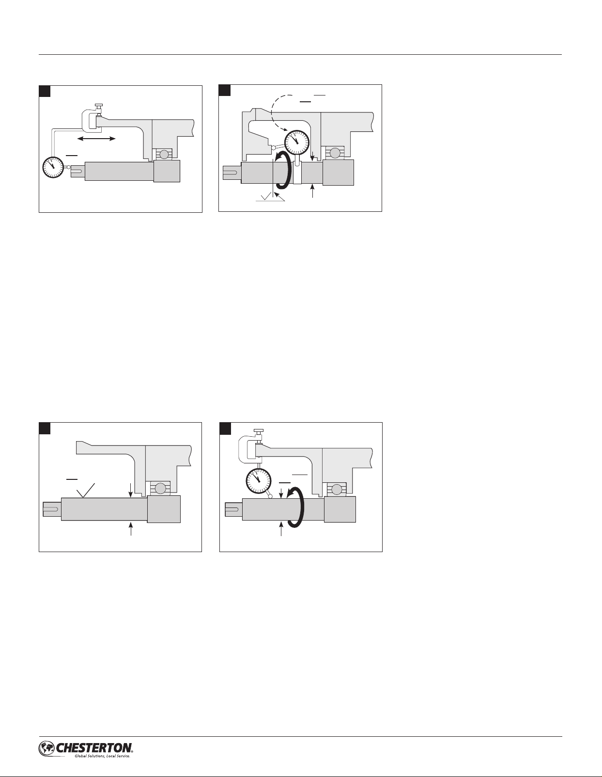
4.1 Equipment
1
.005"
<
0,13 mm
If practical, place the dial indicator tip
on the end of the shaft sleeve or on a
step in the shaft to measure end play.
Alternately push and pull the shaft in
the axial direction. If the bearings are
in good condition, end play should not
exceed 0,13 mm (.005").
3
32 µ"
R
0,8 µm
a
.002"
±
0,05 mm
ø
<
2
125 µ"
3,2 µm
<
ø
200
ø
If possible, attach a base dial indicator
to the shaft and rotate both the
indicator and shaft slowly while reading
the runout of the stuffing box face.
Misalignment of the stuffing box face
relative to the shaft should not exceed
0,005 mm TIR per mm (.005 in per inch)
of shaft diameter.
The stuffing box face must be flat
and smooth enough to seal the
gland. Surface roughness should
be 3,2 microns (125 microinch) Ra
maximum for gaskets and 0,8 micron
(32 microinch) Ra for O-Rings. Steps
between halves of split case pumps
should be machined flat. Make sure the
stuffing box is clean and clear along its
entire length.
4
ø
<
1000
ø
4.2 Mechanical Seal
1. Check the chemical listing to
determine if the O-Rings installed in
this seal are compatible with the fluid
being sealed.
2. CAUTION: If the seal is operating at
a stuffing box pressure over 20 bar
(300 psig) for sizes 25 to 60 mm (1" to
2 1/2"), or 16 bar (250 psig) for sizes
65 to 120 mm (2 5/8" to 4 3/4"), or if
the shaft is case-hardened, replace
the 316 stainless steel set screws
with the hardened steel set screws
supplied with the seal. The 1/4 dog
point set screws go into the small
holes in the sleeve. Do not disengage
these screws from the sleeve when
positioning the seal. The cup point set
screws go through the larger holes
in the sleeve. Make sure all screws
are engaged in the sleeve but do not
protrude into the ID bore. Also, when
repositioning or removing the seal,
make sure the centering clips and
socket head cap screws are engaged.
3. Centering clips have been preset
at the factory. If for any reason you
loosen or remove the centering clip
cap screw, retighten as follows prior to
installing the seal on the equipment:
Tighten the cap screw finger tight.
Then using hex wrench, tighten cap
screw an additional 1/8 turn. This will
approximate the 3,4 Nm (30 inchpounds) of torque for sizes 45 to 60
mm (1.75" to 2 1/2"), and 4,5 Nm
(40 inch-pounds) of torque for 65 to
120 mm (2 5/8" to 4 3/4") set at the
factory. For sizes 25 to 43 mm (1"
to 1.625") tighten the button head
screws to 2,3 Nm (20 inch-pounds) of
torque.
Remove all sharp corners, burrs, and
scratches on the shaft, especially in
areas where the O-Ring will slide, and
polish if necessary to achieve a 0,8
micron (32 microinch) Ra finish. Make
sure the shaft or sleeve diameter is
within 0,05 mm (.002") of nominal.
Use a dial indicator to measure the shaft
runout in the area where the seal will
be installed. Runout should not exceed
0,03 mm TIR per mm (.001 in per inch)
of shaft diameter.
9
Page 10
5.0 SEAL INSTALLATION
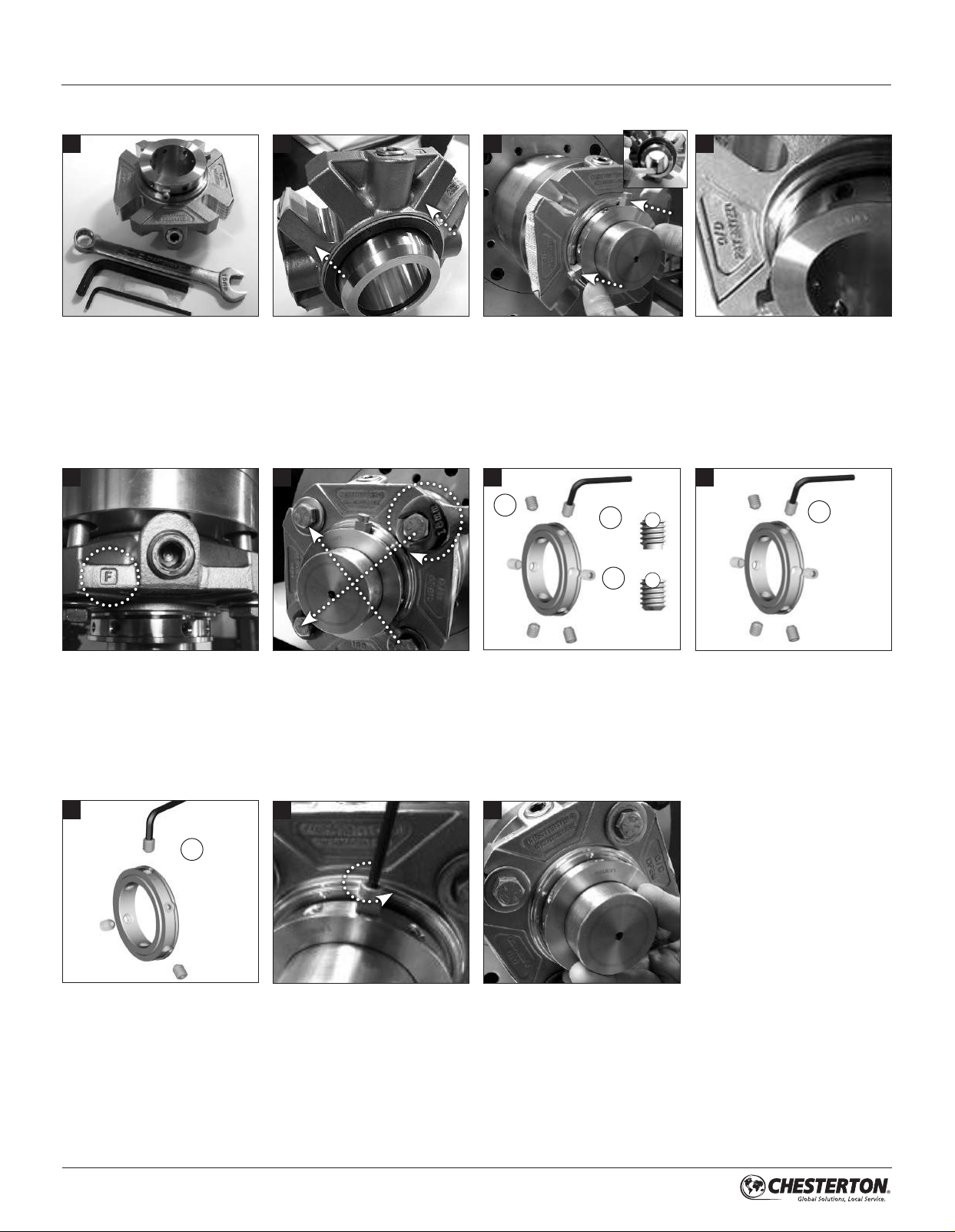
Seal depicted is with a cast gland. Product may be provided with machined gland.
1
Tools required for installation:
Hex wrenches and grease
(supplied with seal); open
end or socket wrench (size
dependent on mounting bolt
size).
5 6 7 8
2 3 4
Ensure that the gland face
gasket or O-Ring is fixed in
the gland gasket ( or O-Ring)
groove. CAUTION: Some gland
gaskets are supplied as a loose
item with no adhesive. Ensure
that gasket remains in place
during installation.
Apply a thin film of grease to the
shaft O-Ring and slide seal onto
the shaft by pushing on the lock
ring. CAUTION: Ensure that all
set screws are engaged through
the sleeve but do not protrude
into the sleeve ID bore.
2
1
1
2
2
Reassemble the pump
and make necessary shaft
alignments and impeller
adjustments. The impeller can
be reset at any time, as long
as the centering clips are in
place and the seal set screws
are loosened while the shaft is
being moved.
1
x3
Orient the flush connection
(marked F) to the location
required. The port is plugged
prior to shipping.
9 10 11
2
x3
Tighten three cup point set
screws (2) evenly with the hex
key provided. IMPORTANT:
After all sets screws have been
tightened by hand, retighten with
a torque wrench:
Sizes 25 to 60 mm (1" to 2 1/2")
to 5,6 to 6,8 Nm (50 to 60 in-lbs)
Sizes 65 to 120 mm (2 5/8" to
4 3/4") 7,3 to 8,5 Nm (65 to 75
in-lbs)
Tighten the gland bolts evenly.
IMPORTANT: The gland bolts
must be tightened before
tightening the screws onto the
shaft. IMPORTANT: Piping
connections should not be
made prior to tightening the
gland bolts.
Remove all centering clips
and retain for future use when
making impeller adjustments.
IMPORTANT: 1/4 dog point set
screws (1) must be tightened
FIRST and cup point set screws
(2) must be tightened last.
IMPORTANT: To ensure that the gland is properly centered over
the sleeve turn the shaft by hand to make sure the seal turns freely.
If you hear metal to metal contact within the seal, it was improperly
centered. Re-install the centering clips finger tight. Loosen the
gland bolts. Fully tighten clips. Loosen the set screws. Re-tighten
the gland bolts. Re-tighten the set screws. Remove the clips. If
metal to metal contact still exists check the centering of the stuffing
box.
Tighten three 1/4 dog point set
screws (1) evenly with the hex
key provided.
10
Page 11
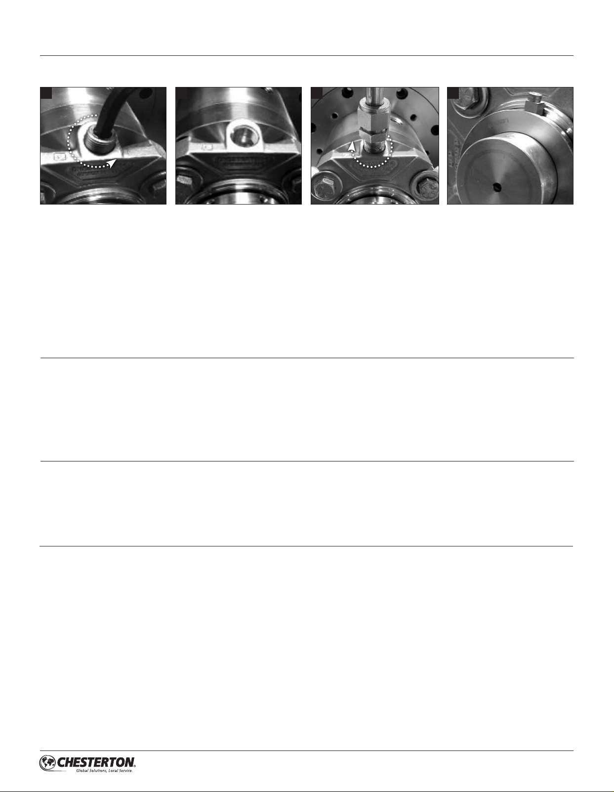
6.0 COMMISSIONING / EQUIPMENT START UP
6.1 Attach appropriate plumbing/environmental controls to the seal.
1
To connect FLUSH: Remove
pipe plug from gland to allow for
installation of flush connections.
Torque required to remove plug:
Sizes 25 to 60 mm (1" to 2 1/2")
67 Nm (50 ft-lbs.).
Sizes 65 to 120 mm (2 5/8" to
4 3/4") 108 Nm (80 ft-lbs.).
2 3 4
Ensure that the port being used
for flush connection is that
which is marked “F”. Ready to
install flush. CAUTION: Quench
and Drain ports are marked
“Q/D” and will be plugged with
plastic cap plugs or pipe plugs
and will also be covered with a
caution sticker.
Install flush line and other piping
as required.
7.0 DECOMMISSIONING / EQUIPMENT SHUT DOWN
Ensure that the equipment is electrically isolated. If the
equipment has been used on toxic or hazardous fluids, ensure
that the equipment is correctly decontaminated and made
safe prior to commencing work. Ensure that the pump is
isolated and check that the stuffing box is drained from any
fluid and pressure is fully released. Disassemble the seal and
remove from equipment in the reverse order from installation
instructions. Incase of disposal, ensure the local regulations
and requirements for disposal or recycling of the different
components in the seal are adhered to
Take all necessary precautions
and follow normal safety
procedures before starting the
equipment.
Please contact Chesterton Mechanical
Seal Application Engineering for
assistance regarding cartridge dual
seals.
8.0 SPARE PARTS
Use only Chesterton original spare parts. Use of non-original
spare parts represents risk of failure, danger to persons/
equipment and voids the product warranty.
9.0 SEAL MAINTENANCE AND REPAIR
9.1 Seal Maintenance
A correctly installed and operated mechanical seal requires little
maintenance. It is recommended to periodically check the seal
for leakage. Wearing components of a mechanical seal such as
seal faces, O-Ring, etc., require replacement over time. While
a seal is installed and operating, maintenance is not possible.
Therefore it is recommended that a spare seal unit or a spare
parts kit be held in stock to allow quick repair.
Spare Parts Kit can be purchased from Chesterton, referencing
the recorded seal data from cover page.
Note the condition of the parts, including elastomer surfaces
and gland springs. Analyze the cause of failure and correct the
problem, if possible, before reinstalling the seal.
Clean all elastomer and gasket surfaces with cleaning solvent.
11
Page 12
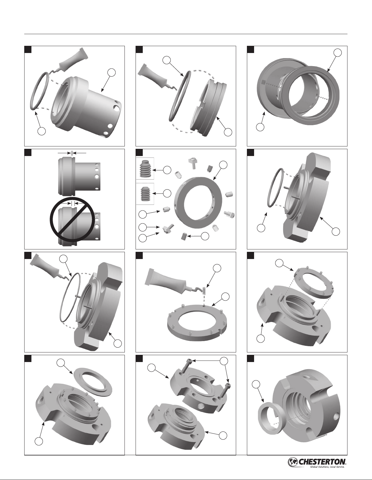
9.0 SEAL MAINTENANCE AND REPAIR (cont.)
9.1.1 Standard Seal Assembly - Seal Sizes: 25 mm to 43 mm (1.000" to 1.625")
1
1
2
3
4
5
2
4
5 6
5
1
16
18
19
18
15
14
7
8
8
19
17
9
12
9
10
9
10
12
13
11
12
11
13
12
20
13
12
7
Page 13
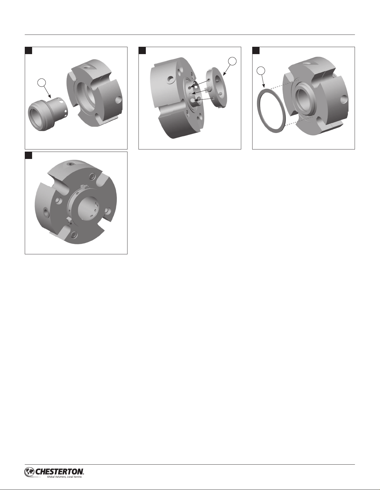
9.0 SEAL MAINTENANCE AND REPAIR (cont.)
9.1.1 Standard Seal Assembly - Seal Sizes: 25 mm to 43 mm (1.000" to 1.625") (cont.)
13
1
16
14 15
16
6
13
Page 14
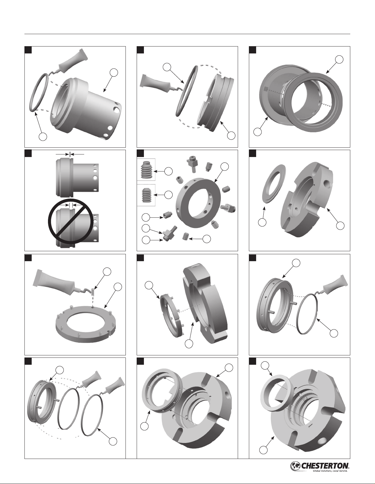
9.0 SEAL MAINTENANCE AND REPAIR (cont.)
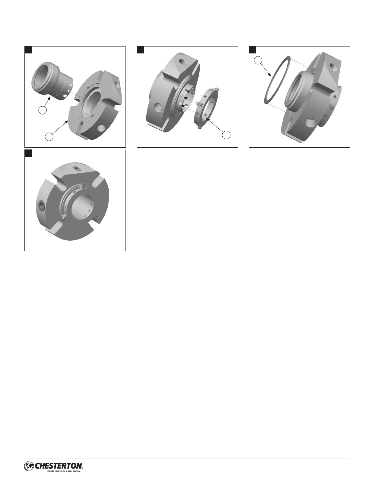
9.1.2 OVERSIZE Gland Seal Assembly - Seal Sizes: 1.125" & 1.375"
1
1
2
4
3
5
2
4
5
18
5
16
1
6
19
18
11
15
14
7
8
19
9
12
8
10
9
9
10
14
17
12
11
8
12
12
7
8
13
12
Page 15
9.0 SEAL MAINTENANCE AND REPAIR (cont.)
9.1.2 OVERSIZE Gland Seal Assembly - Seal Sizes: 1.125" & 1.375" (cont.)
13
14
1
15
6
16
12
16
15
Page 16
9.0 SEAL MAINTENANCE AND REPAIR (cont.)
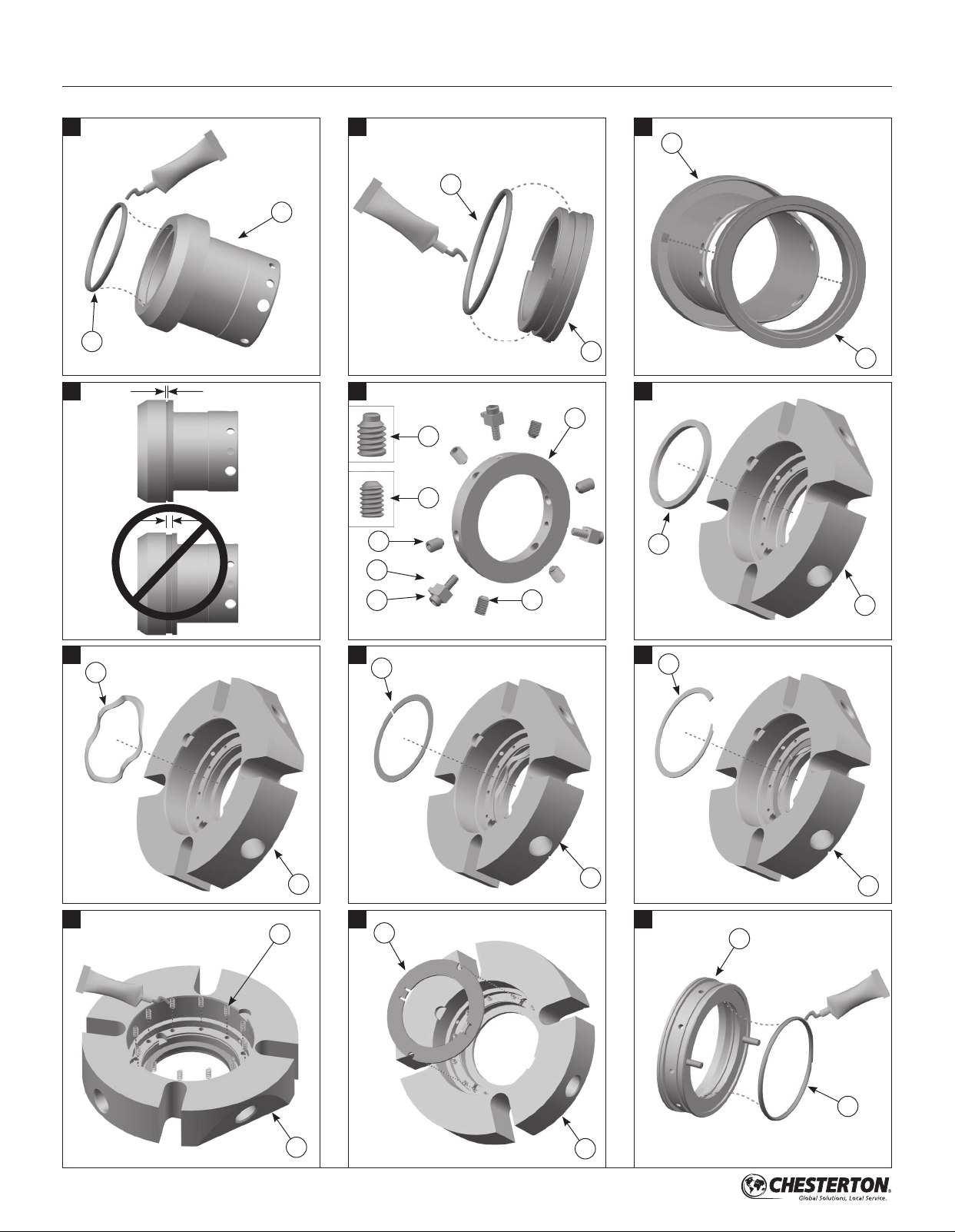
9.1.3 Seal Assembly - Seal Sizes: 45 mm to 120 mm (1.750" to 4.750")
2
4
1
31
1
2
4
5 6
5
5
19
21
22
21
15
18
22
16
97
12
14
17
8
13
16
10 11
11
16
16
10
16
16
16
12
8
9
Page 17
9.0 SEAL MAINTENANCE AND REPAIR (cont.)
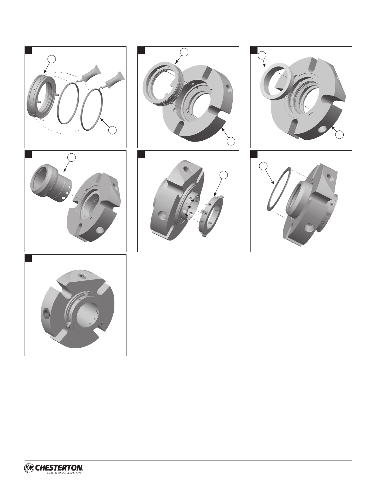
9.1.3 Seal Assembly - Seal Sizes: 45 mm to 120 mm (1.750" to 4.750") (cont.)
13
8
14
8
15
7
16
19
20
16
1
17
19
18
6
16
9.2 Returning Seals For Repair and Hazard Communication Requirements
Any mechanical seal returned to Chesterton that has been in operation, must comply
with our Hazard Communication requirements. Please go to our web page at
www.ches terton.com/Mechanical_Seal_Returns
to obtain information required for returning seals for repair or seal analysis.
17
Page 18

10.0 180H SEAL
10.1 180H Seal Overview
The 180H Seal is a standard 180 Cartridge Single Seal that
uses an advanced hydropad geometry rotary seal face that
improves film formation between the mechanical seal faces
and significantly enhances face lubricity.
Hydropad designs are useful in high pressure applications,
where pressure has a tendency to distort the seal faces, high
speed applications, where the face velocity increases heat
generation and in sealing fluids that have poor lubrication
properties. Combinations of pressure and speed that exceed
the limits of the standard 180 Seal faces would also be potential
applications for hydropad use.
10.2 180H Environmental Control Considerations
Due to the special operating conditions the 180H is designed
for, the seal typically requires environmental controls for
sealing reliability.
In hot water applications such as condensate return
pumps, a Plan 21 Cooled Discharge Recirculation for
cooling will reduce the temperature of the process water,
requiring additional energy requirements to elevate the water
temperature. Where cooling the stuffing box is not acceptable
to the process, there are cases where environmental controls
are not utilized or a Plan 11 Discharge Recirculation
arrangement has been used to improve the conditions inside
the stuffing box without cooling or dilution.
Chesterton Application Engineering can help you specify
the right seal recommendation for the end user including
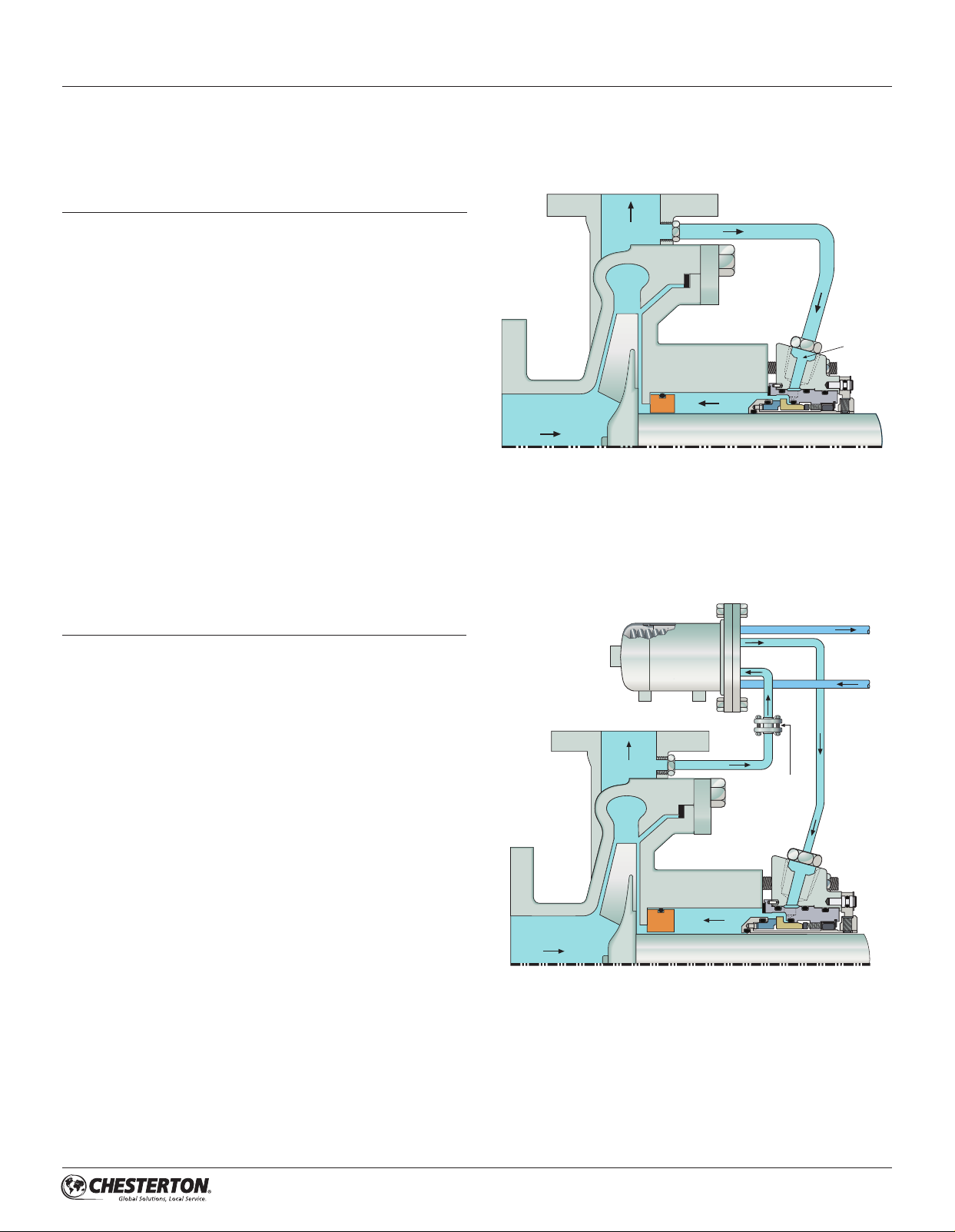
your environmental control options. The 2 diagrams below
illustrate the most common plans used with the 180H Cartridge
Single Seal.
18
Page 19
10.0 180H SEAL (cont.)
PIPING PLAN 11
Discharge Recirculation
PIPING PLAN 21
Cooled Discharge Recirculation
10.2 180H Environmental Control Considerations (cont.)
Pl an 11
Discharge Recirculation
What Discharge recirculation through an orifice to the seal
flush port. The orifice is used to control discharge
pressure to the seal chamber. A smaller orifice allows
less pressure to enter the seal chamber.
Why To raise the pressure in the stuffing box
to prevent flashing at the seal faces; To lower the
temperature at the seal faces by using product to
remove heat from the seal faces.
When With clean process fluids. Process fluids with
particulate may cause abrasion.
PUMP
SUCTION
PUMP
DISCHARGE
OPTIONAL
ORIFICE
FITTING
Plan 21
Cooled Discharge Recirculation
What Discharge recirculation through an orifice and a heat
exchanger to the flush port of the seal. A temperature
indicator can be installed when specified.
Why To raise the pressure in the stuffing box to prevent
flashing at the seal faces; To lower the temperature at
the seal faces by using cooled product to remove heat
from
the seal faces.
When Used with clean fluids. High velocity solids may cause
seal abrasion and score the seal faces if directed by
the flush port.
PUMP
SUCTION
HEAT EXCHANGER
PUMP
DISCHARGE
PRODUCT
OUT
(optional)
INLINE
ORIFICE
COOLANT
OUT
COOLANT
IN
PRODUCT
IN
19
Page 20
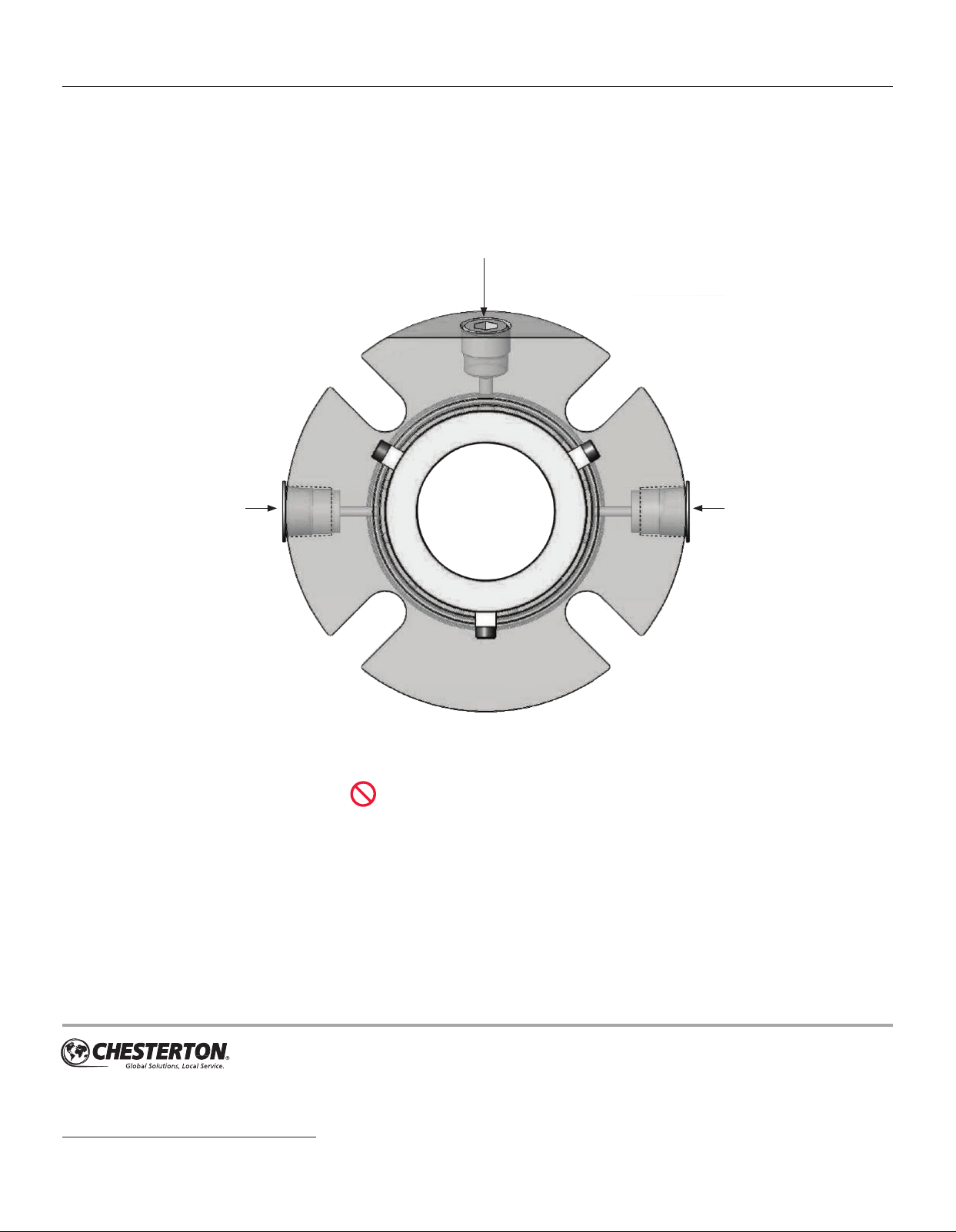
10.0 180H SEAL (cont.)
10.2.1 180H Flush Port Connection
Flush Port
Connect Here
Quench and Drain Port Only
DO NOT Connect Here
Remove pipe plug from flush port. Connect discharge re-circulation to flush port.
DO NOT CONNECT DISCHARGE RECIRCULATION TO EITHER PORT
IDENTIFIED WITH
Quench and Drain Port Only
DO NOT Connect Here
STICKER AS LEAKAGE WILL RESULT.
860 Salem Street
Groveland, MA 01834 USA
Telephone: 781- 438 -7000 Fax : 978- 469- 6528
www.chesterton.com
© 2018 A.W. Chesterton Company.
® Registered trademark owned and licensed by
A.W. Chesterton Company in USA and other countries.
DISTRIBUTED BY:
FORM NO. 072955 REV 7 12/18
Chesterton ISO certificates available on www.chesterton.com/corporate/iso
 Loading...