

Chesney's Beaumont 8SGS, Alpine 6SGS, Belgravia 8SGS, Beaumont 6SGS, Salisbury 8SGS User And Installation Instructions Manual
...Page 1

0
Page 2

1
Technical Manual
PIN: 0558CM1311
User and Installation Instructions
Model No. 8SGS – 6SGS
Model Names
8 Series Gas Stoves
6 Series Gas Stoves
Beaumont 8SGS
Alpine 6SGS
Belgravia 8SGS
Beaumont 6SGS
Salisbury 8SGS
Belgravia 6SGS
Shipton 8SGS
Salisbury 6SGS
Shoreditch 8SGS
Shipton 6SGS
Shoreditch 6SGS
Available in Natural Gas.
IMPORTANT:
Please read these instructions carefully before installation or use.
This appliance must be installed and serviced by a qualified person in
accordance with local and national regulations.
The flue system must be installed and inspected by a qualified person in
accordance with local and national regulations.
Page 3

2
Contents
Section
Pages
1
Unpacking
3 2 Technical data
4-7
3
Installation parameters
8-9
4
Balanced flue configurations / information
10-14
5
Appliance setup information
15-22
6
Control system information
23-34
7
Injector information
35 8 Placement of fibre logs and embers
36-38
9
Commissioning the fire unit
39 - 40
10
Briefing and handover to the customer
40
11
Servicing and maintenance
41-56
12
Fault finding
57
13
User Instructions
58-63
Fireguards
58
Lighting the appliance
60-61
Changing the batteries
62
Cleaning
63
14
Installer checklist
64
15
Dealer and Installer Information
64
16
Annual Service Record
65
Page 4

3
1. Unpacking
Remove the appliance from its packaging, and check that it is complete and
undamaged.
If satisfied by the condition and the contents is as specified, proceed with the
installation.
The installation should only be carried out by a competent person and all gas work
must be carried out by a Gas Safe Registered person in accordance with national
and local regulations for both gas and electricity (If required).
The installation must comply with local and national building regulations.
For the Republic of Ireland, reference should be made to IS813 and ICP3 and any
guidance notes from Bord Gais.
Failure to comply with the regulations nullifies ALL guarantees.
Parts
Gas Stove Appliance 3 Piece log set
Embers Installation Manual
Page 5

4
2. Technical Data
Chesney’s gas stove specifications
Gas Connection Size
8.0mm O.D. tubing
Pilot Assembly
SIT NG 9029
Control System
Mertik Maxitrol GV60 (Radio Frequency)
Appliance Mass Range (kilograms)
65.5-91.0
Gas
Type
Gas Category, Type
and Supply Pressure
Countries of Destination
AT
BG
BE
CH
CZ
DE
DK
EE
ES
FI
FR
GB
GR
HR
IE
IT
LT
NG
I
2H
- G20 at 20mbar
Gas
Type
Gas Category, Type
and Supply Pressure
Countries of Destination
LU
LV
NO
PL
PT
RO
SE
Sl
SK
TR
NG
I
2H
- G20 at 20mbar
Gas
Type
Gas Category, Type
and Supply Pressure
Injector
(1 per appliance)
Nominal Heat Input
kW, Gross/Net
Gas Rate
m3/h
Burner
Pressure (mbar)
Full / Reduced
Efficiency
Class
NOx
Class
Marking
Size
(single)
NG
I
2H
- G20 at
20mbar
1.80
1.8mm
5.6 / 5.0
0.533
19.7 / 14.6
(±0.3)
2
5
Efficiency and Heat Output
Efficiency
%, Net
Heat Output
kW, Net
76.7-81.2
3.8-4.1
Page 6

5
8 Series
Model
Overall dimensions (mm)
Approx.
weight
Balanced
flue
Log
fire
Back and Top
Flue Exits
Flue System
(mm)
W H D (kg)
Alpine 6
460
686
390
91
External 150 (6”)
Internal 100 (4”)
Beaumont 8
642
704
395
76
External 150 (6”)
Internal 100 (4”)
Beaumont 6
522
704
395
68
External 150 (6”)
Internal 100 (4”)
Belgravia 8
642
704
395
77
External 150 (6”)
Internal 100 (4”)
Belgravia 6
522
704
395
69.5
External 150 (6”)
Internal 100 (4”)
Salisbury 8
570
653
428
80
External 150 (6”)
Internal 100 (4”)
Salisbury 6
450
653
428
69
External 150 (6”)
Internal 100 (4”)
Shoreditch 8
568
685
378
72.5
External 150 (6”)
Internal 100 (4”)
Shoreditch 6
448
485
378
66
External 150 (6”)
Internal 100 (4”)
Shipton 8
608
634
378
73
External 150 (6”)
Internal 100 (4”)
Shipton 6
488
634
378
65.5
External 150 (6”)
Internal 100 (4”)
SALISBURY SHIPTON BEAUMONT SHOREDITCH BELGRAVIA
Page 7

6
6 Series
SALISBURY SHIPTON BEAUMONT SHOREDITCH ALPINE BELGRAVIA
Page 8

7
Clearances
The minimum distances between the appliance and any walls and/or shelves are
marked below.
Shelf = 250mm
Wall (side) = 100mm
Wall (rear) = 50mm
It is also advised against placing combustible materials or soft furnishings directly
in front of the appliance.
Main Balanced Flue Parts
Product Code for Stainless Steel
Air Intake Collar
CH 150
Emissions Exit Collar
CH 100
Air Intake Gasket
CH 150G
Emissions Exit Gasket
CH 100G
Blanking Plate Gasket for Air Intake
CH 100G
Wall Terminal Style 1
CH USDHC2 10
Wall Terminal Style 2
CH USDHC3 10
Roof Terminal
CH USDVC2 10
15° Bend
CH USB1510
30° Bend
CH USB3010
45° Bend
CH USB4510
90° Bend
CH USB9010
200mm Straight
CH US2010
500mm Straight
CH US5010
1000mm Straight
CH US10010
Locking Band
CH USKB
Flexi Tube
CH XE/XD
Flue Brackets
CH USMB
Renovation Set
CH USSAN
Renovation Set Top
CH USSAN1 10
Renovation Set Bottom
CH USSAN2 10
Wall Terminal Guard Style 1
CH TG18161 for CH USDHC2 10 Terminal
Wall Terminal Guard Style 2
CH TG11116 for CH USDHC3 10 Terminal
Page 9

8
3. Installation Parameters
This appliance must be installed in accordance with the rules in force, and used
only in a sufficiently ventilated space. Consult instructions before installation and
use of this appliance.
NOTE – This appliance is heavy, care must be taken when installing or servicing to
avoid personal injury.
Wear protective clothing when fitting or carrying works out on the appliance.
For your safety it is law that all gas appliances must be installed by a competent
person, in accordance with the current gas safety regulations applicable in the
country of use.
The installation must be carried out in accordance with the relevant local and
national specifications and comply with current building regulations.
If there is any conflict between these instructions and the current regulations, then
the current regulations are to be followed.
Hearths
The area where the appliance is to be fitted must have a suitable load-bearing
capacity for both hearth and appliance and must stand on a non-combustible
hearth. Check building regulations.
If you are using an existing hearth check it complies with the relevant construction
regulations and is at least the minimum sizes specified.
Hearth and clearance dimensions must comply with the requirements and satisfy
Building Regulations – Approved Document J.
NOTE - The flue must not be shared with any other appliance.
Before installation, ensure that the local distribution conditions (identification of the
type of gas and pressure) and the adjustment of the appliance are compatible.
Before the appliance is installed, the flue must be inspected to ensure that it is
structurally sound and free from obstructions.
Before the appliance is installed ensure the correct restrictor plate is fitted and the
aeration is set for the type of flue installation.
For opening the door please read instructions on page 43.
The flue must be fitted in accordance with Local and National regulations.
The flue system must be in good condition, meet all regulations and work correctly.
The flue must be inspected by a competent person and passed for use with the
appliance.
It is advised that flue specialist inspect the flue system on an annual basis to
ensure that the flue system is sound and the combustion products outlet (terminal)
is clear of obstruction.
Page 10

9
It is advised that provisions be made for the removal of the appliance without the
need to dismantle the flue system.
The gas connection must be in accordance with Local and National regulations.
This appliance is intended for use on a gas installation with a governed meter.
The pilot fitted to this appliance is not to be adjusted or put out of action. If the pilot
is damaged or faulty it should be replaced only with the original identical unit
supplied by Chesney’s Limited.
The appliance is not fitted with an integral guard. It is recommended that a guard
be used for the protection of young children, the elderly or infirm and also for
normal use conforming to BS8423:2002, such that access to the hot appliance is
minimised.
Do not place combustible materials directly in front of the appliance. Floor
coverings, such as carpets, are considered to be acceptable.
All parts of the appliance are hot so can be considered to be a working surface.
Due to the newness of materials, the fire may give off a slight smell for a period of
time after commissioning and that a window or door to the outside can be opened
to ventilate the odours. This is quite normal due to the curing of paints and
materials avoid touching the paintwork during this curing process, any odours
should disappear within a few hours of operation.
Page 11

10
4. Balanced flue configurations / information
Positioning of balanced flue outlets.
Minimum Distances for terminals
1) 1500mm from a structure on the roof.
2) 600mm above the highest point of intersection with the roof.
3) Flue must not penetrate the shaded area (separation distance of 600mm).
4) Flue must not penetrate the shaded area (separation distance of 2000mm).
5) 300mm below gutters, soil pipes or drain pipes.
6) 300mm below the eaves.
7) 300mm above the ground, roof or balcony level.
8) 300mm below an opening.
9) 300mm horizontally from a terminal on the same wall.
10) 600mm from an internal or external corner or to a boundary alongside the
terminal.
11) 1200mm vertically from a terminal on the same wall.
12) *300mm above an opening.
13) 600mm below a balcony or car port roof.
14) 1200mm from an opening in the car port into the building.
15) 600mm from a surface or boundary facing the terminal.
16) *300mm horizontally to an opening.
17) 300mm from a vertical drain pipe or soil pipe.
18) 600mm from a terminal facing the terminal.
Note * An opening – meaning an openable element e.g. an openable window,
a fixed opening such as air vents.
In addition the terminal should not be nearer than 300mm (natural draught) to
an opening in the building fabric formed for the purpose of accommodating a
built-in element such as a window frame.
Page 12

11
Types of chimney or flue
Chesney’s Gas stoves are Balanced Flue appliances this means they vent directly
outside through a co-axial tube (one tube within a larger tube). The outer tube
draws air in from the outside and the inner tube expels the combustion gases.
These appliances can be routed through an existing chimney, a pre-fabricated flue
or where a room has no chimney.
Below are flue systems available for all 8 series and 6 series gas stove
models.
Balanced Flue
A Balanced Flue consists of a tube inside a larger
tube that emits products of combustion and an
outer tube feeds outside air into the stove for
combustion.
If the room has no chimney a balanced flue option
can be used.
Options
1. Top flue exit /up and out :
Vertical - 1m minimum, Horizontal –
475mm maximum (length of wall terminal
piece)
or
Vertical - 1.5m minimum, Horizontal –
1m minimum / 7m maximum plus length of
wall terminal
2. Top flue exit :
Vertical 1m minimum / 8m plus length of
terminal
3. Top flue exit / offset vertical :
1m minimum to first bend / 8m maximum
flue length.
4. Rear flue exit vertical :
Horizontal - 0.5m minimum / 1m
maximum, Vertical – 1.0m minimum
Page 13

12
Vertical Terminal
Vertical terminal – CH/USDVC2 10 Full
flue restrictor fitted
The appliance is usable with:
1. 1.0m minimum vertical height up to
a height of 8.0m plus length of
terminal.
Other combinations are possible provided
the vertical height is not below the
minimum.
Page 14

13
Up and out the wall Terminal
Wall terminals – CH/USDHC2 10
/ CH/USDHC3 10
No flue restrictor fitted
The appliance is usable with:
1. a 1.0m minimum vertical with
a maximum horizontal length of
0.475m (length of wall terminal
piece).
2. a 1.5m minimum vertical with
a maximum horizontal length of
7.475m (length of flue sections
and wall terminal piece).
Other combinations are possible
provided the vertical height is not
below the minimum and the
maximum horizontal length is not
exceeded.
Vertical Terminal rear flue exit
Vertical Terminal – CH/USDVC2 10
Part flue restrictor fitted
The appliance is usable with:
1. a 0.5m to 1.0m (maximum)
horizontal length with a minimum
vertical length of 1.0m and a
maximum of 8.0m plus terminal.
Page 15

14
Terminal Guards
The flue outlet should be protected with a terminal guard if persons could come into
contact with it, or if it could become damaged or if a flue outlet is in a vulnerable
position such as where the flue discharges is within reach from the ground (less
than 2 meters), balcony, veranda or an opening window.
Sealing the flue to the appliance
The flue must be sealed to the appliance to ensure the products of combustion do
not enter the room.
A suitable heat proof sealant that can withstand temperatures of up to 1200°C is
recommended.
Apply a bead of sealant to the inner face of the outer flue collar and the outer face
of the inner flue pipe then attach the flue to the collars.
Page 16

15
5. Appliance setup information
Chesney’s Alpine
WARNING – This appliance is heavy
Lifting this appliance requires 2 persons.
Handle the appliance with care to avoid damage.
Page 17

16
The images below are of the Salisbury – Appliances Shoreditch, Shipton,
Beaumont, and Belgravia have the same controls, body and internals, only the top
panel, legs and door have differences.
All appliances are supplied with a metal data plate attached to it and must remain
with the appliance for annual services.
Image of the data plate shown below:-
Page 18

17
Changing the flue opening
For opening the door please read instructions on page 43.
If the flue is to be changed to run through the rear of the appliance follow these
steps.
Step 1
Alpine model
Remove the door by taking the weight of the door at 90° remove the hex socket
bolts circled to release the door clear from the hinges and remove the controls
access door.
Other models remove the stove top.
Step 2
Remove the rear exit panel by cutting off the lugs to access the rear blanking
plates.
Step 3
Remove both blanking plates.
Page 19

18
Step 4
(Alpine model only)
Remove the 4 securing bolts shown below to allow the movement of the gas cube
in the cladding.
Step 5
(Alpine model only)
Remove the inner flue collar then unscrew the outer flue collar by moving the gas
cube slightly within the cladding to access all the screws.
Step 6
(Alpine model only)
Lift the gas fire cube clear from the Alpine cladding to release the outer flue collar.
Page 20

19
Step 7
Swap over the flue collars and blanking plates and ensure all parts are sealed then
refit the fire cube.
Step 8
Refit the door and adjust the box within the Alpine cladding to re-line up the door
then re-tighten up the bolts then fit the blanking plate over the opening.
Page 21

20
Fitting the restrictor plate
Important
Before fitting the appliance check the flue setting to see if a flue restrictor plate is
required.
All wall terminals (CH/USDHC2 10 / CH/USDHC3 10) do not require a restrictor
plate.
Both restrictor plates are fitted as standard, if they are to be adjusted or removed,
access is made by removing the baffle plate via the 5 screws circled below.
NOTE: The baffle plate must be refitted.
(Below shows image behind the baffle plate)
The appliance is supplied with restrictor plates and are attached to either the
opening or the blanked off opening via 2 x 7mm nuts.
Only certain configurations use restrictor plates and these are listed in the table
below (also refer to pages 12-13):
Restrictor
Configuration
Vertical Terminal [CH USDVC2 10]
Top Flue Connection
Up and Out Wall Terminal
[CH USDHC2 10 or CH USDHC3 10]
Vertical Terminal [CH USDVC2 10]
Rear Flue Connection
Part Restrictor X X
Full Restrictor X
X
Full Restrictor Plate shown below
Part Restrictor Plate shown below
Page 22

21
IMPORTANT NOTE
Setting up the aeration.
The appliance aeration must also be set according to how the flue is set.
Under the appliance is a screw located next to the injector, when screwed fully out
the aeration is closed and when screwed fully in the aeration is open.
Only adjust the aeration when the appliance is cool.
Using a mirror can help locate the adjustment screw.
The screw can be adjusted by using a short cross headed screw driver.
The appliance aeration should be set when the particular flue configuration has
been chosen and before the appliance has been operated for the first time.
If the appliance is fitted with:
- the vertical roof terminal [CH USDVC2 10] configuration, the aeration must be
adjusted so that the aeration is at the Minimum setting;
- the Up and Out wall terminal [CH USDHC2 10 or CH USDHC3 10]
configuration, the aeration must be adjusted so that the aeration is at the
Maximum setting;
- the vertical roof terminal [CH USDVC2 10], rear flue configuration, the aeration
must be adjusted so that the aeration is at the Maximum setting;
A summary of the allowable aeration/restrictor and flue configurations is given in
the table below as follows:
Restrictor
Configuration
Vertical Terminal [CH USDVC2 10]
Top Flue Connection
Up and Out Wall Terminal
[CH USDHC2 10 & CH USDHC3 10]
Vertical Terminal [CH USDVC2 10]
Rear Flue Connection
Part Restrictor X X
Full Restrictor X
X
Aeration Setting
Minimum (fully closed)
Maximum (fully open)
Maximum (fully open)
IMPORTANT NOTE – THE AERATION SCREW IS FACTORY SET & SEALED IN THE FULLY
CLOSED POSITION if the aeration is to be adjusted the screw must be re-sealed after setting. (Paint
is to be used to seal the threads).
Alpine model Other models
Page 23

22
All Chesney’s appliances have been tested to ensure safety.
NOTE – All gas work must be carried out by a qualified gas installer to all relevant
regulations.
Ensure that the gas supply is capable of delivering the required amount of gas, and
is in accordance with the rules in force.
Lay the appliance in the desired area to note where the appliance’s gas inlet
location to ensure a smooth run.
An isolation valve or valves must be fitted near to the appliance in accordance with
national regulations to allow the complete removal for maintenance or repair.
Before connecting the fire unit purge the pipes from air and debris.
Page 24

23
6. Control system information
Features and Options
No external electrical power required.
Used with standard thermocouple and standard ODS pilot
Flame height adjustment with remote control or switch
Compact design with large capacity
Thermoelectric flame failure device
Safety interlock
Pressure regulator or throttle
Minimum rate selling with fixed or adjustable orifices
Pilot gas adjustment screw
GV60 models require no external electrical power to operate. The batterypowered motor allows main gas adjustment via an electric switch or remote.
The thermoelectric flame failure device functions with all standard
thermocouple and ODS pilot burners (no powerpile necessary).
Page 25

24
WARNING
Fire or explosion hazard. Attempted disassembly or repair of controls can cause property damage,
severe injury or death. Do not disassemble the gas valve; it contains no serviceable components.
For your safety, read the user instructions before attempting to light the appliance.
Do not store or use gasoline or other flammable vapors and liquids in the vicinity of this control or other
appliances.
WHAT TO DO IF YOU SMELL GAS
Do not try to light any appliance.
Do not touch any electrical switch; do not use any phone in your building.
Immediately call the gas supplier from a neighbour’s phone. Follow the gas supplier’s instructions.
If you cannot reach the gas supplier, call the fire department.
Installation and service must be performed by a qualified installer, service agency or the gas supplier.
The installation must conform with local codes or in the absence of local codes, with the National Fuel
Gas Code, ANSI Z223.1/NFPA 54 or The International Fuel Gas Code or B149.1 in Canada.
All piping and tubing must comply with local codes and ordinances.
Do not use this control or any gas appliance if any part has been under water or in contact with water.
Immediately call a qualified service technician to replace the control system and any gas control which
has been under water or in contact with water.
COMPONENTS
The standard GV60 system consists of the
following components (see figure 1).
Gas Combination Control (GV60 Series)
with:
ON/OFF switch with soldered cable or
Thermo current cable #2 interrupter –
receiver
Thermo current cable #1 interrupter –
receiver
Thermo current interrupter block
Ignition cable
Remote Control
Remote handset
Receiver
8 wire cable (connects valve to receiver
Figure 1; GV60 components
Page 26

25
TECHNICAL SPECIFICATIONS
Gas combination control according to CSA or CE approval (see label for certification)
Fuels:
CSA: Suitable for use with natural, manufactured, mixed and propane (LP) gases and LP gas-air
mixtures.
CE: Suitable for use with gases of EN 437 gas family 1,2, and 3.
Approvals:
ANSI Z21.78/CSA 6.20 FOR U.S. & Canada.
CE: Gas Appliances Directive 90/396/EEC and EN126
Pressure Drop/Capasity:
CSA : 1’’ W.C. at 65,000 BTU/hr.
CE: 2,5 mbar at 1,2m³/h air
Range of Regulation:
CSA: 10,000 to 85,000 BTU/hr.
CE: Class C according EN88
Regulator Adjustment:
CSA:3” W.C. to 5” W.C. (7.5 to 12 mbar); 8” W.C. to 12” W.C. (20 to 30 mbar); 3” W.C. to 12” W.C. (7.5
to 30 mbar)
CE: 5 to 40 mbar; 7,5 to 30 mbar
Max. Ambient Temperature:
32°F to 176°F (0°C to 80°C)
Mounting Position:
Mount valve 0° to 90° in any direction (Including vertically) from the upright position of the gas control knob.
Max. Inlet Pressure:
CSA: ½ psi (34.5 mbar)
CE: 50 mbar (20”W.C.)
Main Gas Connection:
CSA: 3/8 in. NPT; Rp 3/8 ISO 7-1 internal thread for 12mm, 10mm, 8mm, 6mm outside diameter tube.
CE: Rp 3/8 ISO 7-1 internal thread for 12mm, 10mm, 8mm, 6mm outside diameter tube
Inlet and Outlet Connection:
At side or bottom
Pilot Gas Connection:
CSA: 7/16-24 UNS for 1/4” or 3/16” tubing
CE: M10x1 for 4mm or 6mm tubing
Thermocouple:
11/32 UNS, M10x1, M9x1, M8x1
Maximum allowed torque inlet and outlet:
CSA: 280 inch-pounds
CE: 35 Nm
Page 27

26
Remote
NOTE: These remote handsets, receiver, wall switches, switch panels and touch pads are not
interchangeable with previous versions.
Approvals:
ANSI Z21.20/CSA 6.20 for U.S. & Canada.
CE: Gas Appliances Directive 90/396/EEC and EN298-2003
Max. Ambient Temperature:
Remote Handset and Receiver: 140°F (60°C)
Wall Switch/Touch Pad: 176°F (80°C)
Switch Panel: 221°F (105°C)
8 Wire Connecting Cable, Thermo Current Cable: 221°F (105°C)
Ignition Cable: 302°F (150°C)
Batteries – Remote Handset:
1 x 9V Block (quality alkaline recommended)
Batteries – Receiver:
4 x 1.5V “AA” (quality alkaline recommended)
An AC Mains Adapter may be used instead of batteries (only the Mertik Maxitrol AC Mains Adapter or one
approved by Mertik Maxitrol can be used).
NOTE: During a power outage the AC Mains Adapter must be unplugged from the receiver to
operate in the battery mode.
INSTALLATION INSTRUCTIONS
Read these instructions carefully. Failure to follow them could damage the product or cause a hazardous
condition. These instructions are not to supersede the appliance manufacturer’s instructions.
WARNING
It is the appliance manufacturer’s responsibility to determine GV60’s suitability for a specific application.
WARNING
Do not remove screws from the gas valve. Do not adjust and/or alter any components marked with
tamper indicating paint; Motor knob is not to be removed.
WARNING
Oxygen Depletion is a hazard and can cause injury or death due to asphyxiation. Use only components
intended for vented gas appliances on vented appliances and unvented gas components on unvented
gas appliances.
1. Turn off gas supply at the appliance service valve before starting installation, and perform a Gas Leak
Test after the installation is complete.
2. Install the sediment trap (where required) in the gas supply line to prevent contamination of the gas
valve.
3. Use only your hand to push in or turn the gas control knobs. Never use tools. If a knob will not push
in or turn by hand, don’t try to repair it, call a qualified service technician. Force or attempted repair
will void warranty and can result in a fire or explosion.
Location
Locate the combination gas valve where it is not exposed to steam cleaning, high humidity,
dripping water, corrosive chemicals, dust or grease accumulation or excessive heat. To
assure proper operation, follow these guidelines:
Locate combination gas valve in a well-ventilated area.
Mount combination gas valve high enough to avoid exposure to flooding or splashing water.
Page 28

27
Make sure the ambient temperature does not exceed the ambient temperature ratings for each component.
WARNING
GV60 standard version is suitable for indoor use only.
CONNECTIONS – MAIN AND PILOT GAS
WARNING
Fire or Explosion Hazard. Can cause property damage, severe injury or death. Do not bend tubing at
gas valve connection point after compression fitting has been tightened. This can result in gas leakage at the
connection.
All piping must comply with local codes and ordinances or with the National Fuel Gas Code, ANSI Z223.1/NFPA
54 or The International Fuel Gas Code or B149.1 in Canada. Tubing installation must comply with approved
standards and practices.
1. Use new, properly reamed pipe free from metal or material chips. When tubing is used, assure that the ends
are square, deburred and clean. All tubing bends must be smooth and free of distortion.
2. Run pipe or tubing to the valve.
3. Install a sediment trap (where required) in the supply line to the gas valve (see figure 2)
Figure 2: Sediment Trap (where required)
WARNING
The main gas valve must be disconnected from the gas supply piping system during any pressure testing of
the gas supply piping system at test pressures in excess of ½ psi (3.5 kPa CSA; 50 mbar CE).
Connection Main Gas (Tubing Connections)
1. Mount valve 0° to 90° any direction (including vertically) from the upright position of the gas control knob.
2. Slip nut and ferrule over tubing.
3. Insert tubing into inlet/outlet connection until it bottoms, slide ferrule and gland into place and turn finger tight.
Do not use pipe joint compound.
4. Use a wrench to tighten gland about 1 turn beyond finger tight.
Connection Main Gas (Pipe Connections)
1. Mount valve 0° to 90° any direction (including vertically) from the upright position of the gas control knob.
2. Pipe to be inserted into the valve must be the proper thread length and to gauge. Thread that is cut too long
can cause distortion or malfunction if inserted too deeply.
3. Apply a moderate amount of approved pipe sealant to the pipe only, leaving the two end threads bare.
(Do not use Teflon® tape.)
Connect pipe to valve inlet and outlet. When threads are tightened, the valve must be held at the designated
points (see figure 3). Do not apply pressure to top casting or plastic cover. Check all connections for leaks
Page 29

28
Connection Pilot Gas (Tubing Connections)
1. Ensure tubing end is square and free from burrs.
2. Insert pilot tubing into pilot outlet using fitting provided until it bottoms, and turn finger tight. Do not use
pipe joint compound.
3. Turn with wrench until you shear off the ferrule. Turn an additional ¾ turn to make a gastight seal.
4. Connect other end of tubing to pilot burner according to the manufacturer’s instructions.
Figure 3: S=Clamp Areas, B=Mounting Points
PERFORM GAS LEAK TEST
WARNING
Do not overtighten connections. Overtightening can damage the control body resulting in leakage or control
malfunction.
1. Using a clean brush, apply an approved leak test solution to the pipe connections. Bubbles indicate a leak.
2. If a leak is detected, tighten pipe connections.
3. Light the main burner.
4. With the main burner in operation, apply an approved leak test solution to all pipe connections (including
adapters) and the valve inlet and outlet. Bubbles indicate a leak.
5. If a leak is detected, tighten pipe connections (including adapters).
6. Replace parts if the leak cannot be stopped.
WIRING CONNECTIONS
WARNING
Wiring of valve and receiver must be completed before starting ignition. Failure to do so could damage
electronics.
Total resistance of the thermocouple circuit should be minimised to assure proper operation.
When GV60 components are installed, make sure they are not exposed to dirt, oil, grease or other
chemical agents.
Do not permit foreign particles under plastic cover.
Wiring must comply with diagram.
Place ON/OFF switch (if equipped) where it is easily accessible for the User.
Thermo Circuit
NOTE: The use of the Mertik Maxitrol interrupter block is recommended with the following connections.
Keep connection of Interrupter Block and Thermocouple clean and dry. Avoid severe bending of the
Thermocouple tubing during installation (min. 1” radius; 2.5cm) as this may cause it to fail.
Fasten ring terminals from Thermo Current Cable #1 and Thermo Current Cable #2 (or optional ON/OFF
Switch with soldered cable) tightly on the receiver with screws provided.
Install the interrupter block ¼ turn more than hand tight into the valve. Insert the spade connectors in the slots
(possible from both sides). Screw thermocouple hand tight into the interrupter block and tighten ¼ turn to
ensure a good electrical connection. Tighten only the thermocouple not the interrupter block.
Page 30
29
Ignition Cable
NOTE: Do not damage the ignition cable while attaching it to the ignition electrode. When the cable is in
place, avoid contact with sharp objects or edges.
Cables longer than 900mm, avoid contact with metal parts, as this could decrease spark.
Attach ignition cable to receiver tab 2.8 x 0.8mm (SPARK), and connect other side to ignition electrode.
Receiver
NOTE: To keep the receiver free from debris and dirt, Do not remove the receiver from the plastic bag until all
construction is complete. During a power outage the AC Mains Adapter must be unplugged from the
receiver to operate in battery mode.
Snap the plug of the 8 wire cable in the receptacle on the valve and receiver.
Insert batteries. Do not use metal tools. Using a metal tool could cause a short that may damage the
receiver.
Place ON/OFF switch (if equipped) to ON position.
Check the reception. If necessary, correct position of antenna by moving the antenna cable to a position that
allows for good reception.
When the RF-receiver is placed in the appliance, the surrounding metal can reduce reception considerably.
The position of the antenna on the receiver also influences reception.
The antenna must not come in contact or cross the ignition wire, this may render the receiver
inoperable.
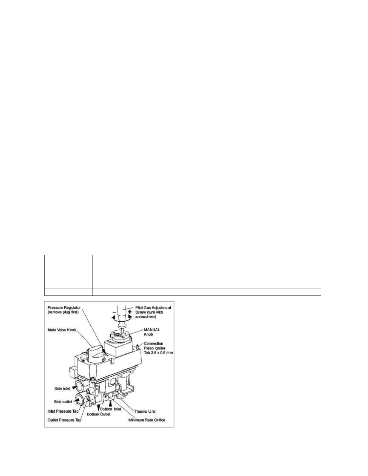
GAS CONTROL KNOB SETTINGS
Gas control knobs function as follows (see figure 4):
KNOB
POSITION
FUNCTION
Main Valve
OFF
Prevents main gas flow through valve.
Main Valve
ON
Permits main gas flow through valve if the pilot is lit and thermocouple is
generating sufficient power.
MANUAL knob
MAN
Allows the pilot to be manually ignited and prevents main gas flow.
MANUAL knob
ON
Allows for automatic ignition.
Figure 4: Combination Control GV60, Connections and Adjustment Options
Page 31

30
ADJUSTMENT
WARNING
Do not adjust ODS (vent free) pilot.
WARNING
It is the appliance manufacturer’s responsibility to determine GV60’s suitability for a specific application.
WARNING
Do not attempt to remove screws from the top of the gas valve. Do not change any adjustments marked
with tamper indicating paint; Motor knob is not to be removed.
WARNING
Oxygen Depletion is a hazard and can cause injury or death due to asphyxiation. Use only components
intended for vented gas appliances on vented appliances and unvented gas components on unvented gas
appliances.
Pilot Flame adjustment
The pilot flow adjustment is pre-set to maximum at the factory. The pilot flame should envelope 3/8” to 1/2" of
the thermocouple – vented only (see figure 5).
1. The adjustment screw can be reached through a hole in the MANUAL knob (figures 4 and 8).
2. Turn the MANUAL knob to the ON position.
3. It is now possible to pierce through the film on the cover with a screw driver to reach the adjustment
screw beneath.
4. Turn the adjustment screw clockwise to decrease or counterclockwise to increase pilot flame.
Figure 5: Proper Flame Impingement on thermocouple
Outlet Pressure Adjustment
Pressure regulator or throttle are located under the cover and can be reached by removing the plug (see
figures 4 and 6).
WARNING
Do not exceed the input rating stamped on the appliance nameplate, or the manufacturer’s recommended
burner orifice pressure for size orifice(s) used.
WARNING
For complete combustion, be sure the primary air supply to the main burner is adjusted properly. Following
the instructions of the appliance manufacturer.
1. Connect a pressure manometer to the valve outlet pressure tap. Pressure tap is opened by turning the
screw counterclockwise .
2. To access regulator adjustment remove plug first (figures 4 and 6).
3. Turn MANUAL knob and main valve knob to the ON position.
4. Turn pressure regulator adjustment screw, accessible through opening in top of cover, to set required
burner pressure (high fire). Pressure is increased by turning clockwise (pressure regulator models),
or decreased by turning counterclockwise .
NOTE: Throttle models pressure is increased by turning counterclockwise ; or decreased by turning
clockwise .
5. After adjustment, replace the plug.
6. If no other adjustments are required, close pressure tap(s) by turning the screw(s) full clockwise .
Check all connections/pressure tap(s) for leaks.
Page 32

31
7. If the desired outlet pressure or flow cannot be achieved by adjusting the gas valve, check the gas valve
inlet pressure using a manometer at the valve inlet pressure tap. If the inlet pressure is in the normal
range, replace the gas valve; otherwise take the necessary steps to assure proper gas pressure to the
valve.
Minimum Gas Flow Adjustment (for CE Use only) (See figure 4)
1. Set the control into low fire setting by turning the motor knob in OFF-position and back until the valve
opens.
2. The minimum rate can be set either by screwing in a calibrated minimum rate screw (fixed orifice) or an
adjustable minimum rate screw. Controls with adjustable screws without a customer specific setting are
factory set at maximum flow.
3. Turn the screw clockwise to decrease the minimum flow.
4. Care should be taken to screw the fixed orifice until it stops.
5. Close pressure tap(s) by turning the screw(s) full clockwise . Check all connections/pressure tap(s)
for leaks.
Figure 6: Combination Control GV60, Cover
FINAL CHECK
Observe several complete cycles to ensure proper operation. During these cycles the electronics will
determine the optimum ignition sequence timing.
1. STOP! Read the safety information included before proceeding.
2. Turn main valve knob to the OFF, full clockwise position.
3. Place ON/OFF switch (if equipped) to the O (OFF position).
4. Wait five (5) minutes to clear out any gas. Verify that no gas is in the area around the appliance,
including near the floor. If you detect gas STOP! Follow “A” in the safety information of the
Operating Instructions. If no gas is present, proceed according to the Mertik Maxitrol Operating
Instructions GV60-OI-EN.
WARNING
Fire or explosion hazard. Attempted disassembly or repair can cause property damage, severe injury or
death. Do not disassemble the gas valve; it contains no serviceable components.
Page 33

32
OPERATING INSTRUCTIONS - FOR OEM USE ONLY
WARNING
Fire or explosion hazard. Attempted disassembly or repair of controls can cause property damage, severe
injury or death. Do not disassemble the gas valve; it contains no serviceable components.
If the information in this manual is not followed exactly, a fire or explosion may result causing property
damage, personal injury or loss of life
A. BEFORE OPERATING verify that no gas is in the area around the appliance, including near the floor.
WHAT TO DO IF YOU SMELL GAS
Do not try to light any appliance.
Do not touch any electrical switch; do not use any phone in your building.
Immediately call the gas supplier from a neighbour’s phone. Follow the gas supplier’s instructions.
If you cannot reach the gas supplier, call the fire department.
B. Use only your hand to push in or turn the gas control knobs. Never use tools. If a knob will not push in
or turn by hand, don’t try to repair it, call a qualified service technician. Force or attempted repair may
result in a fire or explosion.
C. Do not use this control or any gas appliance if any part has been under water or in contact with water.
Immediately call a qualified service technician to replace the control system and any gas control which
has been under water or in contact with water.
D. These instructions are to be referenced as a user guide, and do not supersede appliance
manufacturer’s lighting instructions.
APPLICATION
GV60 is a battery-powered electronic remote ignition and control system for gas appliances with
pilot burners and ODS systems
Figure 8 Combination Control GV60
Figure 7 Combination Control GV60
Page 34
33
GENERAL NOTES
Batteries – Remote Handset:
1 x 9V Block (quality alkaline recommended)
Batteries – Receiver:
4 x 1.5V “AA” (quality alkaline recommended)
An AC Mains Adapter may be used instead of batteries (only the Mertik Maxitrol AC Mains Adapter or one
approved by Mertik Maxitrol can be used).
NOTE: During a power outage the AC Mains Adapter must be unplugged from the receiver to operate in the
battery mode.
TO TURN OFF APPLIANCE
Press OFF button on remote handset.
NOTE: Press (small flame) to turn main gas to pilot gas.
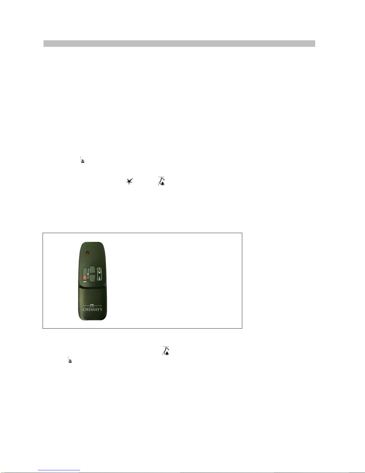
Remote Handset (see figure 9)
Simultaneously press and hold (star) and (large flame) until a short acoustic signal confirms the start
sequence has begun; release buttons.
Continuing signals confirm the ignition is in process.
Once pilot ignition is confirmed, there is main gas flow.
NOTE: If the pilot does not stay lit after several tries, turn the main valve knob to OFF and follow the
instructions “Turn Off Gas to Appliance”.
WARNING – The appliance will get
hot whilst running; do not place the
remote handset on the appliance.
Figure 9 Remote Handset
Remote Handset (see figure 9)
To increase flame height press and hold the (large flame) button simultaneously.
Press (small flame) to decrease flame height or to set appliance at pilot flame.
For fine adjustment tap the large flame or small flame. There is a separate OFF button
NOTE: If the appliance will not operate, follow the instructions “TURN OFF GAS TO APPLIANCE”.
With very low battery the GV60 system shuts off the fire completely. This will not happen if the
power supply is interrupted.
Battery replacement
Battery replacement is recommended at the beginning of each heating season. Do not use metal tools to
remove batteries. Using a metal tool could cause a short that may damage the receiver.
Page 35

34
Page 36

35
Back log retaining bracket / pilot shield
The back log retaining bracket / pilot shield is located above the pilot and is
attached to the pilot bracket.
The back log sits on top of the bracket to ensure the log is in the correct area and
the bracket also improves pilot flame stability.
7. Injector information
NG Elbow Injector – Single hole drilled at 1.8mm
Only use genuine Chesney’s parts
Page 37

36
8. Placement of fibre logs and embers
Logs and glow embers are only available from Chesney’s stockists.
Important notes:
The placement of fibre logs and embers must be installed in accordance with these
instructions; any deviation may cause poor combustion.
If any of the components of the log effect burner are broken DO NOT INSTALL.
Do not to add more fibre logs onto the fire bed than specified.
This appliance is supplied with 3 fibre logs, and embers these must be placed in
the appliance as specified in this manual.
Log Placement
Log 1 must be fitted so that the mesh is located in the slot on the back of the log
pushing the log so that the location point is against the location pin.
Slot on the back of log 1 Location Point
Location Point Mesh Log behind this screw
Log 2
Log 2 has a location hole on the right side of the log.
Page 38

37
Locate the hole on the pin attached to the perforated bed laying the log against the
back wall of the appliance.
Embers
Place the embers all around log 1 ensuring there are no embers under log 2.
Log 3
Place log 3 so that the end of the log sits on the ledge of the bracket circled below
Page 39

38
On the underside of log 3 is a raised area this is to locate in the groove on Log 1
Lay the log at a 45 degree angle so that the log locates in the groove on log 1.
Fit the log retainer.
Page 40

39
9. Commissioning the fire unit
Turn on the gas supply.
Check the gas supply and gas appliance for soundness.
The appliance must be fully fitted, the door and glass on the appliance must be
sealed. Check areas around the door for gaps and that the rope seal is tightly
sandwiched between the door and enclosure. Check the glass for movement or
gaps and that there is no damage to the gaskets.
Lighting the appliance for the first time.
IMPORTANT NOTE - Ensure the door is firmly closed and locked before
turning on the appliance. Do not run the appliance if the is door open or if the
door glass has been removed or damaged.
When lighting the appliance for the first time, the materials (i.e. paint, sealants etc.)
may give off an unpleasant odour. This is quite normal and will disappear after a
few lightings. During this period, keep the room well ventilated.
Light the appliance and check that all available functions work correctly.
(See ‘Lighting the appliance’ in User Instructions for information).
Flame stability
The appliance should always be observed when lighting.
On starting the appliance an acoustic signal confirms the ignition is in process
IMPORTANT NOTE - The pilot will light soon after the acoustic signal has been
activated observations can be made by looking through the glass on the right side
under the back log.
If the pilot flame is extinguished either intentionally or unintentionally, allow 5
minutes before attempting to relight the appliance.
Once the acoustic signal stops the main valve opens to ‘High rate’ to allow gas
through to the main burner. All of the main burner should light within 6 seconds
lighting the whole burner area.
IF THIS DOES NOT HAPPEN THEN THE APPLIANCE SHOULD BE TURNED
OFF ALLOWING 5 MINUTES BEFORE ATTEMPTING TO RELIGHT.
Check the stability of the flame by turning to low rate then back to high rate then to
low rate doing this around three times whilst observing both pilot and main burner
flame, there should be no problems lighting the main burner.
Light the fire on maximum and run for at least 30mins or until the logs start to glow
before turning the appliance to low rate.
NOTE – The flames will start off blue until the appliance has heated properly before
turning more yellow.
With the appliance door closed check that all the products of combustion are
entering the flue and that no products of combustion are entering the building.
IMPORTANT- The door must be locked once the appliance has been commissioned.
Page 41

40
Alpine models - Lock the door using a hex key Other models – Lock the door using a
castle nut spanner clockwise to tighten
10. Briefing and handover to the customer
Instruct the customer on the full operation of the appliance.
Warn the customer that the fire unit may give off a temporary odour; this is normal
running in of the unit, and will disappear after a short period of use.
Inform the user that the appliance door is only to be opened when servicing, and
not to disturb the fibre logs as this may disturb the combustion.
Inform the customer that it is recommended that a full service on the fire unit and
flue checks be carried out annually by competent person/s.
Inform the user to always observe the appliance when lighting, once the acoustic
signal stops the main valve then opens to ‘High rate’ allowing gas through to the
main burner. The main burner should then light within 6 seconds IF THIS DOES
NOT HAPPEN THEN THE APPLIANCE SHOULD BE TURNED OFF ALLOWING
5 MINUTES BEFORE ATTEMPTING TO RELIGHT.
Instruct the customer that the pilot and flame sensing device fitted to the unit is
designed to shut off the appliance if the evacuation of the products of combustion
is interrupted.
If the appliance cuts off repeatedly then a qualified person is to be informed.
Warn the user that all parts of the appliance will become hot while the appliance is
running, so it is recommended that a guard conforming to BS8423: 2002 be used
for the protection of young children, aged or infirm persons.
Ensure the battery compartment is easily accessible so that the batteries can be
changed without the need to open the door and inform the user where it is placed.
Also advise the user not to stand too close to the appliance for prolonged periods
of time; loose clothing is particularly at risk of burning, and that rubbish cannot be
burned in the unit.
Advise the user against placing combustible material directly in front of the
appliance. Floor coverings, such as carpets, are considered to be acceptable.
Ensure the installer details are filled in.
Handover the installation manual to the customer.
Page 42

41
11. Servicing and maintenance
It is advised that the appliance is serviced annually by a qualified person to
Local and National Regulations.
Only carry out maintenance work when the appliance is cool.
Exchangeable components list
Pilot unit (natural gas) SIT-NG9029
Gas Injector (Natural Gas) Single hole / dia.1.8mm
Control Valve GV60
Controls Box Radio Frequency
Logs
Glow Fibre
Embers
Annual maintenance.
Safety precautions must be taken when cleaning the appliance.
Ensure the appliance is cool before carrying out a service.
Isolate the appliance and disconnect the unit.
Always test for gas soundness and spillage after refitting the appliance.
Check all logs, pilot burner/ignition unit, for soot or debris deposits.
Replace all misplaced logs and retest.
On the failure of pilot burner/ignition, or control valve have repairs carried out by a
competent person.
Paintwork
It is generally accepted that stove paintwork may need a light re-spray occasionally
after a seasons use, stoves painted in a lighter colour are more likely to require
this.
Touch-up spray is available from most Chesney’s stockists.
Wear appropriate safety equipment.
Ensure that there is adequate ventilation and that areas to be sprayed are clean and
dry. Make sure that all parts and the surrounding area that do not require paint are
properly masked up.
NOTE – Only re-spray when the appliance is off and cool following the safety
guidelines when carrying out such work.
Page 43

42
Door Handle information
Alpine model
To remove the handle unscrew the door locking grub screw then turn the
handle180° and remove the screw on the door handle boss.
On the underside of the handle boss is an opening, the handle must be facing
upwards to access the grub screw.
Using a 3mm Hexagon Key unscrew (counterclockwise) the grub screw to loosen
the handle and pull the handle and door boss from the mechanism.
Other models
Using a 3mm Hexagon Key unscrew (counterclockwise) the grub screws to loosen
the handle and pull the handle from the mechanism.
Page 44

43
Opening the door should only be carried out by a Gas Safe Registered
person
Important note - The door must only to be opened when servicing the appliance.
Only open the door when the appliance is off and cool.
Alpine model
On the Alpine the door is fitted with a grub screw to stop the door from being
opened (shown below). To open the door unscrew the grub screw using a 3mm
Hexagon key this releases the door mechanism to allow the handle to be turned.
When the service has been carried out close the door and refit the grub screw.
Other models.
Using the Castle nut spanner (provided) undo the castle nut to allow the handle to
open the door.
When the service has been carried out close the door then refit the locking nut and
door handle.
Page 45

44
Changing the door glass
Note attention must be paid to the curing time and temperature rating of the
silicone used with the glass and door seals.
Replacement glass is only available from Chesney’s stockists.
Only carry out a service or repair when the appliance is cool.
If the glass is damaged such as cracks or breaks do not use the fire until the glass
is replaced.
Wear appropriate safety equipment and take care when removing the glass panel.
On changing the glass the glass seal must also be renewed to ensure a good seal.
Remove the glass retaining brackets via the two screws on each side and gently
push the glass out.
Fit the seal using high temperature sealant and then re-fit the glass.
Check the glass panel has no movement within holder and is properly sealed to the
door.
Replacing the door rope
The door rope is a perishable item and at some point may need changing.
If the door rope is frayed and starting to leak emissions then it must be replaced.
The stove rope and rope adhesive are only available from most Chesney’s
suppliers.
Remove the old seal and clean off any dirt and old adhesive from around and in the
seal channel.
Dry fit the seal and cut off any overlapping excess.
Add a small bead of adhesive around the channel and then fit the seal into the
channel, wiping off any excess glue.
Close the door to press the seal in place and allow the glue to dry, before re-using
the appliance all replacement parts should be checked for leakage of combustion
products
Page 46

45
Adjusting the door seal
Important note - The door should only be opened when switched off and only if
the appliance requires maintenance.
Ensure the door is properly sealed.
To adjust the seal on the left hand side for Beaumont, Salisbury, Shipton, and
Belgravia firstly undo the grub screw to allow the handle to turn fully (Shoreditch
and Alpine models do not have the grub screw fitted).
Turn the door handle 360° counter clockwise turns to pull the door in or turn 360°
clockwise turns to adjust out.
Door seal adjustment on the left side
Door seal adjustment on the right side
To adjust the seal on the right hand side remove the door then turn the hinge 360°
clockwise to pull the door in or turn 360° counterclockwise to adjust out.
Refit the door.
Page 47
46
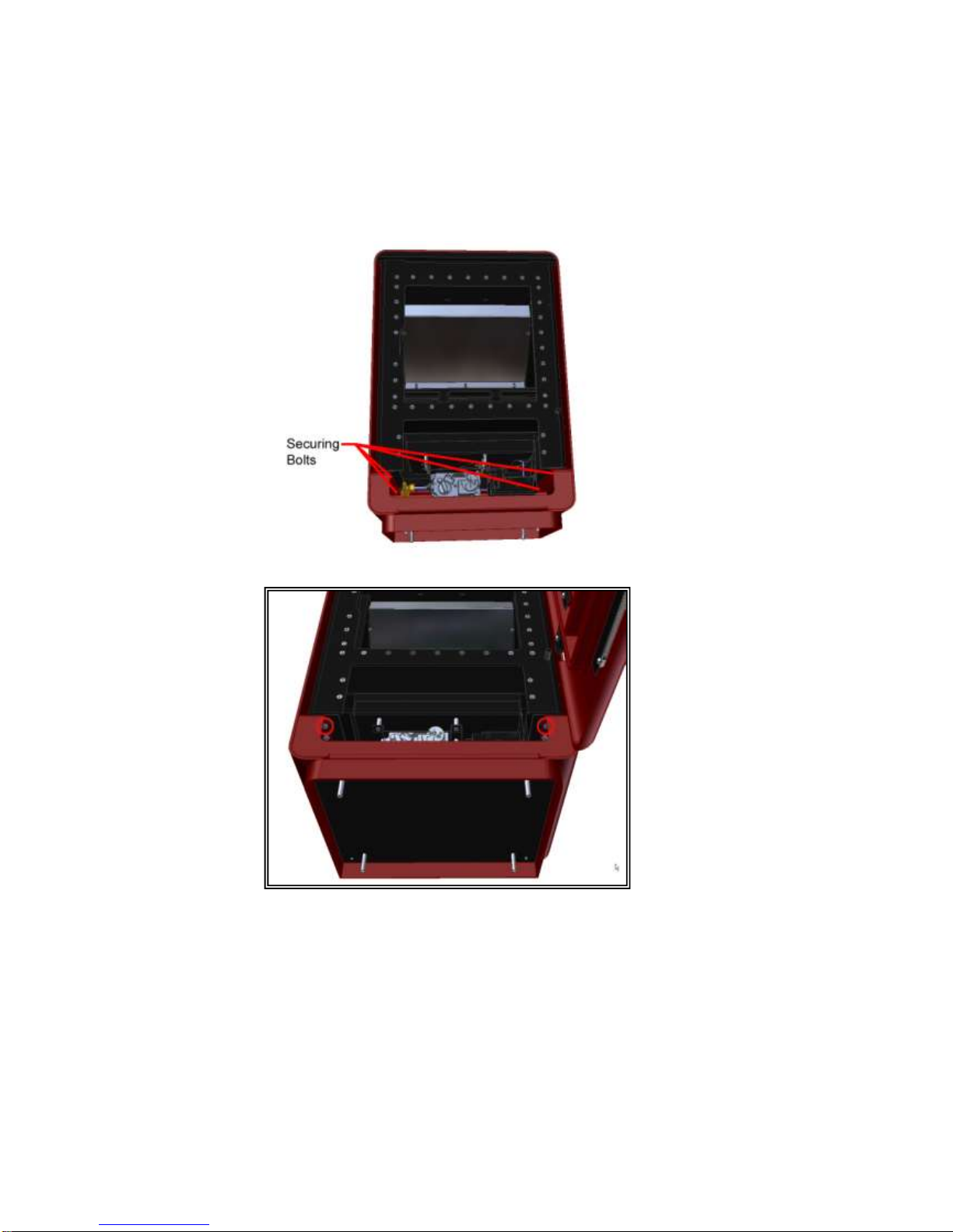
Aligning the door (Alpine models)
To align the Alpine door with the cladding
Undo the 4 securing bolts - 2 at the front and 2 at the back of the appliance.
Move the gas fire cube within the cladding until the door lines up then tighten up
the bolts.
Page 48

47
Removal of the gas cube
Alpine model
Remove all the gas logs and embers from the appliance.
Remove the door by taking the weight of the door at 90° remove the hex socket
bolts circled and lift the door clear from the hinges.
Remove the 4 securing bolts - 2 at the front and 2 at the back of the appliance.
Remove the back panel and if the flue collars exit the top then they also must be
removed.
Lift the gas fire cube clear from the Alpine cladding.
Page 49

48
Removal of the gas cube
All other models
The gas logs and embers must be removed from the appliance.
Remove the top cover.
Open the door and lift the door clear from the hinge pins then remove the controls
cover.
Remove the bolts holding the legs to the gas fire cube a lift away from the legs.
Page 50

49
Pilot Removal
Work should only be carried out by a competent person and all gas work be carried
out by a Gas Safe Registered person in accordance with national and local
regulations.
The pilot to be exchanged must be a genuine like for like part.
Part - SIT Pilot NG9029
Page 51

50
Pilot removal
NOTE – Before removing the pilot ensure you have a seal set. (Only supplied
by Chesney’s).
Isolate the appliance.
Remove the logs and embers.
Remove the log base to access the pilot.
Remove the white heat protective fibre then pull the spark lead from the pilot.
Undo the 4mm tube nut and release from the pilot then remove the pilot shield and
pilot bracket from the enclosure.
Remove pilot exit plate via screws shown below.
Pilot Shield
Pilot Bracket
Page 52

51
Remove the 2 gasket seals and assess for damage and replace if required.
NOTE- One of the gaskets is fitted so that the slots are pointing upwards and the
other fitted downwards to ensure a good seal.
Remove the pilot nut from the valve then pull the pilot free from the appliance.
Replace with genuine parts refitting in the reverse order.
NOTE- The position of the pilot is essential.
Commission the appliance.
Page 53

52
Replacing the pilot spark lead
Isolate the appliance.
Remove the logs and embers.
Remove the log base to access the pilot.
Remove the white heat protective fibre then pull the spark lead from the pilot.
Pull the spark lead from the controls box then pull the lead through the appliance.
Assess for damage to the protective sleeve and replace if required.
NOTE – Protective sleeve are only available from Chesney’s
Replace with genuine parts refitting in the reverse order.
Commission the appliance.
Page 54

53
Control Valve Removal – Mertik GV60 (Fully remote controlled)
Page 55

54
Removing the gas valve
Isolate the appliance.
Release the front panel via the four screws
Remove the cover plate (Beaumont / Belgravia / Shipton) by unscrewing the bolts
at each end using the hexagon key.
Undo the 2 screws holding the valve bracket assembly then slide the bracket
forward to drop the assembly.
Page 56

55
The valve assembly can be turned to access the connections to the injector, pilot
4mm OD tube nut and thermocouple nut.
Undo the screws to release the valve from the bracket.
IMPORTANT – Only use a Chesney’s factory set valve.
Fit the new factory set valve and refit the interrupter block, tube and wiring
connections.
Fit the valve assembly by sliding the bracket tabs in-between the fixing plate on the
underside of the appliance.
Page 57
56
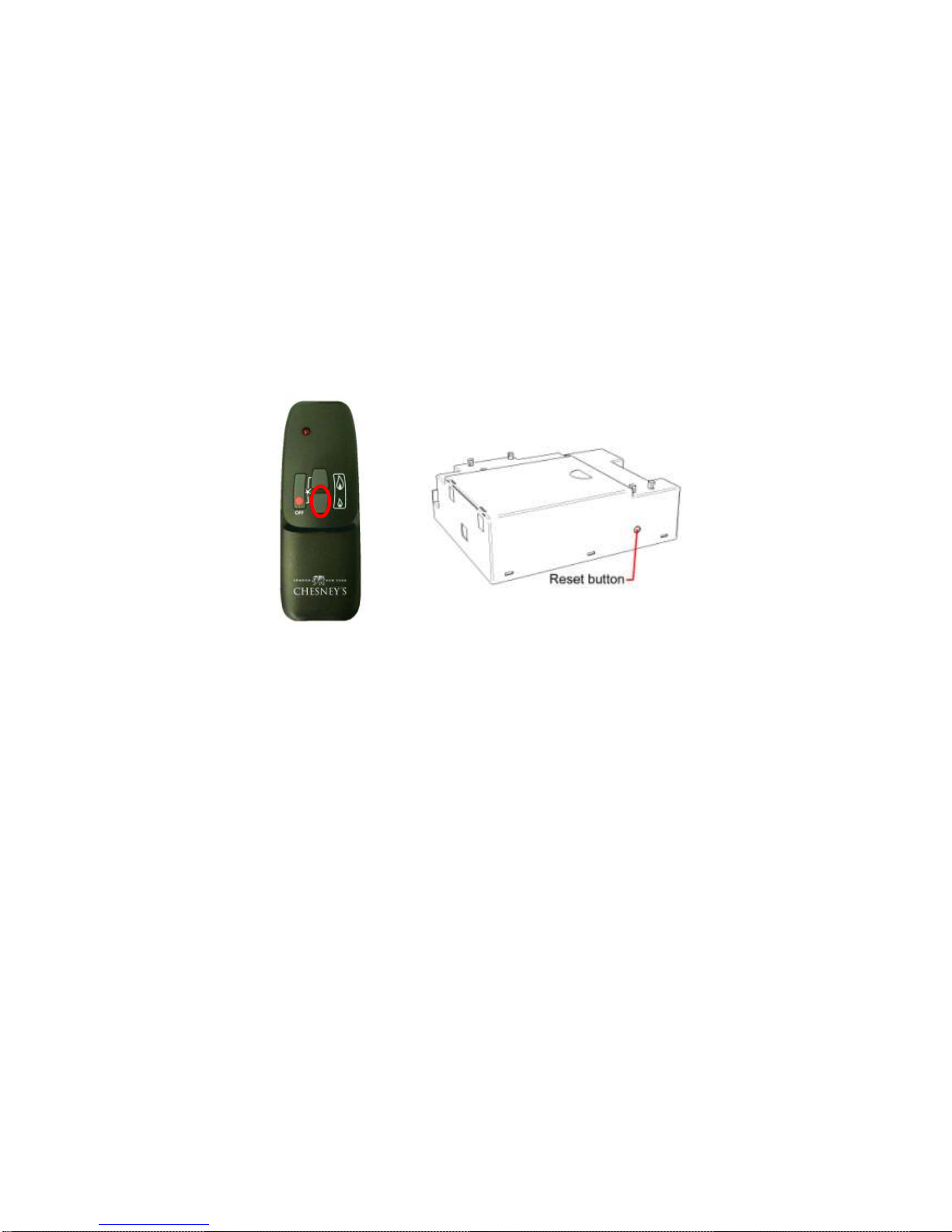
Pairing the handset
The handset has been paired with the appliance at the factory.
If the handset is to be exchanged or is not responding with the appliance then the
control box RF receiver will require setting to allow communication.
The control box RF receiver has to learn the handset code:
Press and hold the control box RF receiver’s reset button until you hear two (2)
beeps. After the second longer beep release the reset button. Within the
subsequent 20 seconds press the small flame (circled) button on the remote
handset until you hear an additional long beep confirming the code is set.
NOTE: This is one time setting only, and is not required when changing the
batteries in the remote receiver.
Page 58

57
12. Fault finding
Symptom
Check List
Unit does not respond.
Check Remote is working properly
Check Battery power supply.
Check wiring is correct.
Remote does not work.
Check Battery Power.
Check Remote eye is visible and facing in the correct position.
Hardwire switch does
not work. (If fitted)
Check Switch is wired properly.
Unit clicks but no spark
or weak spark.
Check spark lead is connected properly.
Check spark electrode is in the correct area and the gap correctly
distanced.
Unit sparks but does not
light pilot.
Check for a good spark.
Check the spark is in the correct area.
Check if the ventilation is not too strong.
Check if there is gas running through.
If there is no gas.
Check isolation tap/shut off valves are free from grease.
Check isolation tap/shut off valve/s are on.
Check for blockages
If there is gas but pilot
does not light
Check pressure is correct.
Check for blockages.
Check for draughts.
Check the pilot gas slots are clear.
Pilot lights but does not
light main burner
Check the pilot flame is heating the thermocouple.
Check the thermocouple nut is properly tightened into the interrupter block.
Check that the pilot lights early on ignition clicks.
Check ventilation is not too strong.
Burner lights but turns
off after a few minutes
Check thermocouple nut is properly secured to the interrupter block.
Check ventilation is not too strong and the flame is not blowing off the
thermocouple.
Check gas pressure is correct.
The GV60 fully remote controlled system has audible beeps to indicate a
problem with the system.
Reason
No Beep
Impulse magnet not operating properly – Replace gas valve
1 Long Beep
ON (1)/OFF(0) Switch is on OFF position – Switch to ON (1)
3 Short Beeps
Low Batteries – Replace receiver batteries with 4x1.5V “AA” quality alkaline
batteries
Page 59

58
13. User Instructions
General
The flue must be fitted in accordance with Local and National Regulations.
The flue must not be shared with any other appliance.
It is advised that flue specialist inspect the flue system on an annual basis to
ensure that the flue system is sound and the combustion products outlet
(terminal) is clear of obstruction.
It is highly recommended that a full service on the appliance be carried out
annually by competent person/s.
The gas connection must be in accordance with Local and National
Regulations.
Installation and servicing must be carried out by a competent person in line with
relevant regulations.
WARNING – Do not use the appliance if the glass front door is broken, removed or
is open.
WARNING – The appliance will get hot whilst running; do not place the remote
handset on the appliance.
All parts of the appliance will become hot while the appliance is running, so it is
recommended that a guard conforming to BS8423: 2002 be used for the protection
of young children (i.e. in nurseries), aged or infirm persons.
Allow adequate clearances for curtains, pictures, soft furnishings, electrical
appliances or any items that may get damaged through heat.
Curtains should not be positioned above the appliance at a distance less than
250mm.
All parts of the appliance are hot so can be considered to be a working
surface.
It is also advised against placing combustible materials or soft furnishings directly
in front or above the appliance. Floor coverings, such as carpets (up to the hearth),
are considered to be acceptable.
Do not throw rubbish in the appliance or otherwise disturb the fuel bed. Debris from
any source, or soot formed, should be removed from time to time.
The pilot light and flame sensing device fitted to this fire shuts off both the main
burner and pilot if evacuation of the combustion products is interrupted.
The pilot is not to be adjusted or put out of action. If the pilot is damaged or
faulty it should be replaced by a qualified person and only with an original
identical unit.
The appliance when lit from cold will start off with a blue flame and will gradually
turn more yellow as the flue, logs and appliance heat up.
Page 60

59
Important notes
The appliance door must only to be opened when servicing the
appliance.
The appliance must not be operated with the door open.
The appliance must not be operated if the appliance glass front is damaged
or has been removed.
The appliance should always be observed when lighting.
Improper installation, service, maintenance, adjustment or
alterations may cause injury or property damage
Do not disturb, add extra fibre logs or embers as this will affect the
combustion.
Do not operate the appliance if the fibre logs are damaged
The appliance must be installed and maintained by a suitably qualified
heating engineer.
Ensure this manual remains with the appliance.
The products of combustion can cause white deposits to appear.
The white deposits are in the gas mixture and can be more noticeable in certain
areas. When burning off the residue it can adhere to moisture, e.g. the glass. It is
advised to remove the residue during a service. NOTE - The longer it stays on the
harder it is to remove.
Use a suitable cleaner such as 'White Off', ‘Brasso’ or a metal polish.
IMPORTANT – Do not use abrasive materials to remove the residue from the glass
as it could etch the glass and make future cleaning harder.
Page 61
60
Lighting the appliance
The GV60 is fully remote controlled.
IMPORTANT NOTE - The appliance should always be observed when lighting.
If the appliance makes a long beep when starting the appliance then the on/off
switch is set on the OFF (0) position, switch the unit to the ON (1) position.
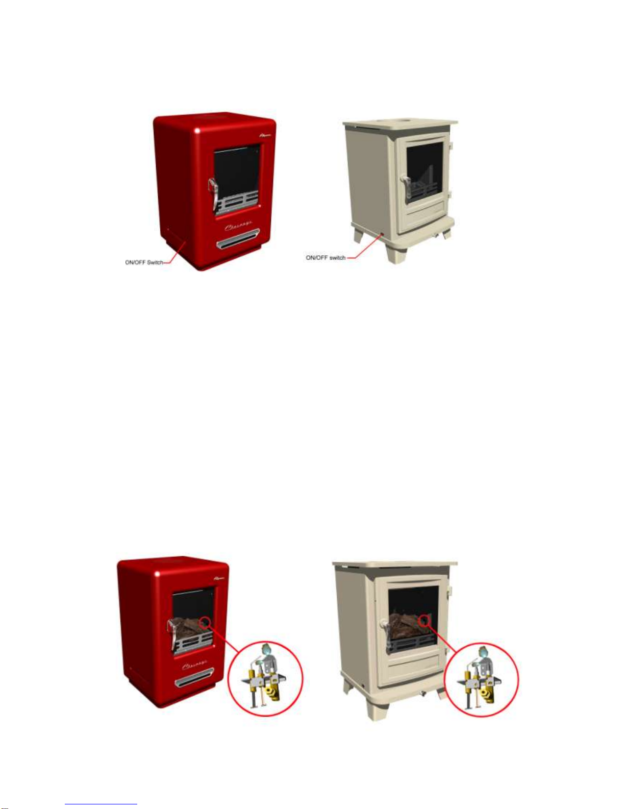
Note - If the handset is out of action or is not obtainable the appliance can be
turned off by pressing the ON/OFF switch to the OFF (0) position (located on the
left side of the appliance). Care must be taken when doing this as the appliance will
be hot.
To light the fire unit you must press and hold both buttons red circle and large
flame button until a short acoustic signal is heard, this confirms that the starting
sequence has begun; release the buttons. Continuing signals confirms the ignition
is in process.
The pilot will light soon after the appliance has been activated observations can be
made by looking through the glass on the right side under the back log.
If the pilot flame is extinguished either intentionally or unintentionally, allow 5
minutes before attempting to relight the appliance.
Page 62

61
When the acoustic signal stops the main valve opens to ‘High rate’ to allow gas
through to the main burner. All of the main burner should light within 6 seconds
lighting the whole burner area.
IF THIS DOES NOT HAPPEN THEN THE APPLIANCE SHOULD BE TURNED
OFF ALLOWING 5 MINUTES BEFORE ATTEMPTING TO RELIGHT.
If lit from cold it is advised to leave the burner on high rate for at least 30 minutes to
warm up the flue before turning between the ‘High’ and ‘Low’ rates.
When the fire has warmed the flame height can be adjusted between ‘High and
Low’ by pressing and holding the large flame button to increase flame height, or
pressing and holding the small flame button to decrease flame height.
The pilot can just remain lit this is done by holding the small flame button until the
fire unit turns off the main burner.
To go from the lit pilot to main press and hold both the red circle and the large
flame button. All of the main burner should then light within 6 seconds lighting the
whole burner area.
If this does not happen then the appliance should be turned off allowing 5 minutes
before attempting to relight.
To turn off the fire unit completely press the off button.
Restarting the appliance
If the fire is extinguished or goes out in use, allow 5 minutes before attempting to
restart following the lighting sequence.
If the fire shuts itself off repeatedly, do not use the fire, and have the flue and fire
checked by a suitably qualified person.
Page 63

62
Changing the batteries
The batteries will require changing yearly (based on the average usage) this may
differ depending on usage and on the quality of battery, the battery change is best
done on the annual service of the appliance.
However if the appliance is showing signs of diminishing signal or during the
lighting sequence then the batteries may need changing.
Firstly replace the handset battery before attempting to change the fire unit battery.
Remote handset battery
1 x 9V block
(Quality alkaline recommended)
Receiver batteries
4 x 1.5V “AA”
(Quality alkaline recommended)
The battery compartment should be placed in an accessible area so that the
batteries can be changed without the need to open the door.
Suggested areas - under the appliance for appliances able to be accessed or for
appliances such as the Alpine or Shipton the battery compartment should be
placed out the back of the appliance.
Ensure to follow direction of the batteries (indicated in the compartment).
Check the connections are secure before replacing the box back in the appliance.
Page 64

63
Cleaning
Cleaning should only be carried out when the fire is turned off and cold.
This appliance contains no asbestos.
Cleaning paintwork
Use a clean soft dry brush to remove dirt and debris from the appliance.
If the appliance has ingrained dirt use soapy water to dampen a soft cloth and use
to clean.
Cleaning Glass
The glass in your stove is specially formulated to withstand very high temperatures.
The products of combustion can cause white deposits to appear.
It is advised to remove the residue during a service.
NOTE - The longer it stays on the harder it is to remove.
Use a suitable cleaner such as 'White Off', ‘Brasso’ or a metal polish.
IMPORTANT – Do not use abrasive materials to remove the residue from the glass
as it could etch the glass and make future cleaning harder.
Fuel bed components
For opening the door please read instructions on page 43.
Wear suitable safety equipment when cleaning the products inside the appliance.
It is advised to wear protective gloves and a dust mask conforming to EN
149:2001+A1:2009 FFP3 (available from most DIY shops) when cleaning the logs
and embers.
It is necessary to clean the fire if debris or soot deposits have accumulated on the
logs. A soft brush is advised to clean the logs and burner unit.
The ceramic parts are fragile; care must to be taken when handling this product.
Warning – Do not change the fuel bed layout or the quantity of material
When placing the logs it is important to carefully follow the layout in this manual
see pages 36-38, the layout has been set to give the best performance and flame
picture of the appliance any deviation may cause poor combustion.
The addition of further ceramic components are strictly prohibited, any extra parts
supplied are spares for future use.
Ceramic components should last around 2 years in normal use at which time is
recommended that they are replaced.
Replacements can be bought from any Chesney’s stockists. State the model
number (found on the gas fire data plate).
Always ask for genuine Chesney’s parts.
This appliance is manufactured by -
Chesney’s Limited
194 – 200 Battersea Park Road,
London, SW11 4ND
Tel: 020 7627 1410 Fax: 020 7622 1078
Page 65

64
14. Installer check list
Flue checklist
PASS
FAIL
Flue Size
Flow test
Spillage test
Gas checklist
PASS
FAIL
Soundness
Standing Pressure
Working Pressure
Ventilation
PASS
FAIL
Ventilation requirements for appliance
15. Dealer and Installer Information
Dealer and Installer Information
Dealer
Installation Company
Contact No.
Gas Safe Registered Engineer
Date of Purchase
Contact No.
Model No.
Gas Safe Register No.
Serial No.
Date of Installation
Gas Type
16. Annual Service Record
Page 66

65
Annual service record
Year 1
Gas Safe Registered Engineer
Contact No.
Gas Safe Register No.
Date of Service
Annual service record
Year 2
Gas Safe Registered Engineer
Contact No.
Gas Safe Register No.
Date of Service
Annual service record
Year 3
Gas Safe Registered Engineer
Contact No.
Gas Safe Register No.
Date of Service
Annual service record
Year 4
Gas Safe Registered Engineer
Contact No.
Gas Safe Register No.
Date of Service
Annual service record
Year 5
Gas Safe Registered Engineer
Contact No.
Gas Safe Register No.
Date of Service
Annual service record
Year 6
Gas Safe Registered Engineer
Contact No.
Gas Safe Register No.
Date of Service
The following information supplied in this manual is correct at the time of publish;
Date of last manual update 26 Feb 2013. V6.
 Loading...