

Chesney's Alchemy GFL850URN, GFL850, GFP700 Swansnest, GFP700 Wigwam, GFP500 User And Installation Instructions Manual
...
0

1
Technical Manual
PIN: 0558CO1462
User and Installation Instructions
Model No. GFL850URN
IMPORTANT:
Please read these instructions carefully before installation or use.
These instructions are only valid if the following country code is on the appliance.
If this code is not present on the appliance, it is necessary to refer to these
technical instructions which will provide the necessary information concerning
the modification of the appliance to the conditions of use for the country.
This appliance must be installed and serviced by a qualified person in accordance
with local and national regulations.
The flue system must be installed and inspected by a qualified person in
accordance with local and national regulations.

2
Contents
Section
Pages
1
Unpacking
3-4 2 Technical Data
5
3
Installation Parameters
6-7
4
Construction Information
8-12
5
Appliance Details
13-14
6
Preparing the Appliance for Installation
15-21
7
Installation
22-36
8
GV60 Control Information
37-48
9
Commissioning the Fire Unit
49-51
10
Briefing and Handover to the Customer
52
11
Servicing and Maintenance
53-61
12
Fault Finding
62
13
User Instructions
63-72
14
Installer Checklist
73
15
Dealer and Installer Information
73
16
Annual Service Record
74

3
1. Unpacking
Remove the appliance from its packaging, check that it is complete and undamaged.
If satisfied by the condition and the contents is as specified, proceed with the installation.
The installation should only be carried out by a competent person and all gas work must be
carried out by a Gas Safe registered person in accordance with national and local regulations
for both gas and electricity (If required).
The installation must comply with local and national building regulations.
For the Republic of Ireland, reference should be made to IS813 and ICP3 and any guidance
notes from Bord Gais.
Failure to comply with the regulations nullifies ALL guarantees.
Parts
Fig. 1 Glass Fronted Appliance Fig. 2 Installation Manual / Warning Label
Fig. 3 Bronze Urn Fig. 4 Interior Panels
Fig. 5 Frame Fig. 6 4mm Ball Head allen Key

4
Fig. 7 Smoke Match Holder Fig. 8 Remote Control Handset
Fig. 9 Pressure Test and Isolation Valve

5
2. Technical Data
Gas Type
Natural Gas
Gas Connection Size
8.0mm O.D. tubing
Pilot Assembly
Seagas P4-41
Control System
Mertik Maxitrol GV60 (Radio Frequency)
Appliance Mass Range (kilograms)
Gas
Type
Gas Category, Type
and Supply Pressure
Countries of Destination
AT
BG
CH
CY
CZ
DE
DK
EE
ES
FI
FR
GB
GR
HR
IE
IT
LT
NG
I
2H
- G20 at 20mbar
Gas
Type
Gas Category, Type
and Supply Pressure
Countries of Destination
LU
LV
NO
PL
PT
RO
SE
Sl
SK
TR
NG
I
2H
- G20 at 20mbar
Appliance
Gas
Type
Gas Category, Type
and Supply Pressure
Injector
(1 per appliance)
Nominal Heat
Input
kW, (Gross)
Gas Rate
m3/h
Burner
Pressure
(mbar)
Efficiency
Class
Marking
Size
(Single
hole)
GFL850Urn
NG
I
2H
- G20 at 20mbar
1.80
1.8mm
5.80
0.552
17.9
2
Appliance
Efficiency
Net %
Gross %
GFL850Urn
74.7
67.3
Appliance
NOx
Class
NOx Concentration / Limits
mg/kWh
GFL850Urn 5 100

6
3. Installation Parameters
This appliance must be installed in accordance with the rules in force, and used only in a
sufficiently ventilated space. Consult instructions before installation and use of this appliance.
NOTE - Wear protective clothing when fitting or carrying works out on the appliance.
For your safety it is law that all gas appliances must be installed by a competent person, in
accordance with the current gas safety regulations applicable in the country of use.
The installation must be carried out in accordance with the relevant local and national
specifications and comply with current Building Regulations.
If there is any conflict between these instructions and the current regulations, then the current
regulations are to be followed.
NOTE - The flue must not be shared with any other appliance.
If the chimney has been used for solid fuel, the chimney must be swept before installation.
The flue must be fitted in accordance with local and national regulations.
Damper plates or restrictor plates must not be fitted in the flue.
The flue system must be in good condition, meet all regulations and work correctly.
The flue must be inspected by a competent person and passed for use with the appliance.
It is advised that a flue specialist inspect the flue system on an annual basis to ensure that the
flue system is sound and the combustion products outlet (terminal) is clear of obstruction.
The flue kit should only be fitted to the appliance where the chimney serving the appliance:
a) Has passed a flue flow test to ensure that the flue is sound and without leaks; and
b) Has been swept if previously used for solid fuel.
The flue kit shall not be fitted to chimney that is likely to have problems with condensation, i.e. a
length in excess of 12m internal or 10m external to the building.
Do not install the appliance in a bathroom or a room that contains a bath or shower.
It is advised that provisions be made for the removal of the appliance without the need to
dismantle the flue system.
Before installation, ensure that the local distribution conditions (identification of the type of gas
and pressure) and the adjustment of the appliance are compatible.
Before the appliance is installed, the flue / chimney must be inspected to ensure that it is
structurally sound and free from obstructions.
Ensure the builders opening and supports are made of non combustible and heat resistant
material.
Do not cover the appliance and or do not wrap it in an insulation blanket or any other material
Do not make any changes to the appliance.
The gas connection must be in accordance with local and national regulations.

7
This appliance is intended for use on a gas installation with a governed meter.
The pilot fitted to this appliance is not to be adjusted or put out of action. If the pilot is damaged
or faulty it should be replaced only with the original identical unit supplied by Chesney’s
Limited.
WARNING - SPILLAGE MONITORING SYSTEM
The appliance is fitted with a thermostatic switch (TTB), which is located in close proximity to
the draught diverter and operates to shut the appliance off if the evacuation of combustion
products is interrupted (for example caused by lack of flue pull or flue blockage). The TTB
MUST NOT be adjusted, modified or put out of action by the installer. The TTB MUST NOT be
removed or ‘bridged out’ for any reason. If the TTB is faulty and requires replacement, only
genuine Chesney’s parts should be used.
When using stone like materials and or plaster finishing, the chimney breast should dry for at
least 6 wks to prevent cracks.
The appliance is not fitted with an integral guard. It is recommended that a guard be used for
the protection of young children, the elderly or infirm and also for normal use conforming to
BS8423:2002, such that access to the hot appliance is minimised.
Do not place combustible materials directly in front of the appliance. Floor coverings, such as
carpets, are considered to be acceptable provided there is a gap of at least 225mm between
the top of the carpet and flame. Where no floor covering is present, it must be at least 300mm
from the finished floor to make allowances for any carpet or combustible floor covering which
may be fitted at a later date.
In case of a damaged or broken glass, do not use the appliance and isolate the gas to the
appliance.
Clean the glass before you use the appliance in order to prevent dirt from burning on the glass.
All appliances are supplied with a metal data plate attached to it and must remain with the
appliance for annual services.
The data plate is attached to a chain (see fig.11) and is placed in the air slot on the base of
the appliance (see fig. 10)
NOTE: DO NOT attempt to remove the data plate while the appliance is HOT!
Fig. 10 Fig. 11

8
4. Construction Information
Hearths
The appliance does not require a hearth if the flame or any incandescent surface is more than
225mm above any floor covering or 300mm with no floor covering.
Any lower than this a hearth conforming to national regulations is required.
Emissions Exit Connection Types
The minimum chimney height is 2 meters from the spigot.
A smoke pellet can be used to test the flue for effectiveness of the draw, light the smoke pellet
and place to the base of the chimney / liner. Check other parts of the dwelling (including loft
areas) for leakage, down draught etc. If the smoke is drawn into the chimney / liner without
problem, continue with the installation.
If there is little or no flow into the chimney preheat the chimney and repeat the smoke test. If
there are still issues with the draw seek expert advice.
NOTE – The smoke test gives a fair idea on the draw, but is no guarantee that the products of
combustion from the appliance will clear. A spillage test is also required after the installation.
If spillage occurs after installation a flue liner may be required.
Conventional Class 1 Chimney
Fig. 12 Fig. 13
IMPORTANT NOTE If the appliance has been installed in a conventional Class 1 chimney with no liner the
debris shield must be used (see fig. 12) and the warning label (supplied in the manual)
must be fixed to the back of the data plate. (see fig.13)

9
Fig. 14 4” (102mm) Flue Liner
If the appliance is fitted with a flue liner the debris shield will not be required (see fig.14).
NOTE – Leave enough flue length to allow connection. The minimum flue liner is 2 meters from
the spigot.
The Builders Opening
Use non combustible heat resistant materials for the chimney breast, including the top of the
chimney breast, the material in the chimney breast and the back wall of the chimney breast.
The construction must comply with all relevant regulations.
The appliance can be used with a sound Class 1 unlined flue with a minimum diameter of 7”
(178mm). If the appliance is used with a lined chimney the minimum flue diameter must be 6”
(152.4mm) or above to accommodate the 4” liner. (see fig. 15)
Fig. 15
Min 7” unlined / Min 6” lined Min 7” unlined / Min 6” lined

10
Start with a builders opening. C is including plaster and skimming (see fig.16)
Appliance
A B C
D
E (Page11)
GFL850Urn
910mm
520mm
355mm
65mm
120mm
Fig. 16 Front elevation Side elevation
The appliance supports are approx. (For measurement ‘D’ See table above) Height 135mm x
Depth 355mm (Including plaster and skimming) (see fig.17)
Fig. 17 Front Elevation Side Elevation
The front filling is approx. Height 110mm x Depth 70mm including plaster and skimming (see
fig.18)
Fig. 18 Front Elevation Side Elevation

11
Gas Route
For your safety it is law that all gas appliances must be installed by a competent person, in
accordance with the current Gas Safety regulations applicable in the country of use.
Ensure that the gas supply is capable of delivering the required amount of gas, and is in
accordance with the rules in force.
When laying the gas pipe work check the fire unit’s gas inlet location to ensure a smooth run.
Lay the appliance in the desired area to note where the appliance’s gas inlet location to ensure
a smooth run.
For ease the gas is best run to the left side of the appliance.
An isolation valve or valves must be fitted near to the appliance in an accessible area, meeting
all local and national regulations this is to allow the complete removal of the burner control
assembly, for maintenance or repair.
The best route for the gas is through the base of the appliance to the position shown in fig.19.
(For measurement ‘E’ See table on page 10)
Fig. 19 Top Elevation
If routed through the back of the appliance the position of the knock out plate is shown in fig.
20. (For measurement ‘E’ See table on page 10)
Fig. 20 Front Elevation

12
Note – This appliance must not be used as part of the wall support structure.
Supports are to be made (see fig. 21) to ensure the appliance does not rest on
the lower tray, leave a gap of at least 20mm under the controls housing, 10mm around the
sides, top and at least 15mm at the back. This space is for the collection of debris.
Fig. 21
Front Elevation Side Elevation
Make sure that the appliance is not carrying the weight of the chimney breast.

13
5. Appliance Details
GFL850Urn
Fig. 22
IMPORTANT NOTE – Allowances must be made for the battery compartment
Suggested opening size for stone slips behind the outer casing flange.
Appliance
Length
Height
GFL850Urn
910mm
410mm
Suggested opening size for stone slips in front of the outer casing flange.
Appliance
Length
Height
GFL850Urn
890mm
375mm

14
Fig. 23

15
6. Preparing the Appliance for Installation
The appliance is supplied in an assembled state minus the Urn and interior panels these are
packed in separate boxes.
Important Notes
Ensure the appliance is cold before undoing the glass fixings.
Care must be taken when using the Allen key to prevent damage to paintwork.
The glass is not bonded to the glass fixing bracket. Hold the glass and the bracket
when fitting to the appliance.
Ensure the glass is clean on both sides before lighting as dirt; oils etcetera can etch the
glass.
Do not clean with abrasive materials as this can accelerate dirt accumulation and
weaken the glass.
Fig. 24
Undo the five glass fixings at the top using the 4mm ball head allen key supplied (see fig. 25)
Fig. 25

16
Remove the 3 hex screws located at the bottom of the glass fixing (see fig. 26).
Fig. 26
IMPORTANT NOTE – The glass is not bonded to the glass fixing bracket. Hold the glass and
the bracket when removing from the appliance.
Lift the glass and bracket from the bottom and lift carefully out from the gap at the top
(see fig. 27)
Fig. 27

17
Remove the burner tray by undoing the 2 securing / levelling screws (see fig. 28).
Fig. 28
Carefully lift the burner from the appliance. NOTE – The burner bed fibre matting used to
spread the flame can irritate the skin when handled and is advised to wear protective clothing.
The fibre matting is also very fragile and must be handled with care to avoid damage.
IMPORTANT – Only use a soft brush to clean the surface. Do NOT use a vacuum to clean the
fibre bed (see fig. 29).
Fig. 29
Lift the burner base assembly to access the wiring.
IMPORTANT NOTE – The wiring attached to the burner base is also attached to the controls
housing below and must be disconnected to remove the burner base from the appliance (see
fig. 30, 31).
Fig. 30 Fig. 31

18
Disconnect the power lead, spark lead cable and 8 core cable from the controls box. (See fig.
32-35).
Fig. 32 Fig. 33
Fig.34 Fig.35
Undo the interrupter nut and pull out the cable / black grommet from the interrupter block. (See
fig. 36-38).
Fig.36 Fig.37
Fig.38

19
Lift the burner clear from the appliance (see fig. 39, 40).
Fig. 39 Fig.40
Carefully pull the base back plate out, the TTB bullet connections are threaded through the
plate hole (see fig. 41-44).
NOTE – The TTB bullet connections are supplied from Chesney’s factory disconnected to avoid
damage to the TTB and are to be connected during installation.
Fig. 41 Fig.42
Fig. 43 Fig.44
Remove the emissions diverters at each end of the appliance (see fig. 45-47).
Fig.45 Fig.46

20
Fig.47
Remove the screws to release the inner casing from the outer casing (see fig. 48)
Fig. 48
Carefully slide the inner casing out (see fig. 49)
Fig. 49

21
Place the outer casing on its back and remove the screws holding the controls housing then
remove the housing (see fig. 50, 51).
Fig. 50 Fig. 51
Remove the screws attaching the spigot and drop the spigot out (see fig. 52, 53).
Fig. 52 Fig. 53
Remove the screws holding the debris shield and drop the shield out (see fig. 54, 55).
Fig. 54 Fig. 55
The outer casing is ready to place in the constructed opening.

22
7. Installation
IMPORTANT The outer casing must be sealed against the front face of the builders opening,
failure to do so may result in spillage problems.
There are 2 debris spacers attached to the back of the appliance and 2 spacers attached to the
base of the appliance (see fig. 56, 57) this ensures the distance of the debris void and must not
be removed.
Fig. 56 Fig. 57
Fit the outer casing in the opening and secure (see fig. 58-60).
There is no need to use all securing points.
Fig. 58 Fig. 59
Back Securing Points Front Securing Points
Fig. 60
Side Elevation

23
Refit and secure the controls housing Fit the debris shield if required (see fig. 62)
(see fig. 61) (Conventional Class 1 chimney with no liner)
Side Elevation Side Elevation
Fig. 61 Fig. 62
Fitting the spigot
Conventional Class 1 chimney with no liner
If the appliance is fitted into a conventional Class 1 chimney with no liner the spigot is still
required. Screw the spigot in place (see fig. 63).
NOTE – The spigot needs to have slight movement only tighten the securing screws so that it
just grips the spigot in position.
Fig. 63

24
Sealing the Flue Liner to the Appliance
The flue must be sealed to the appliance to ensure the products of combustion do not enter the
room.
Use a suitable heat proof sealant to seal the liner to the spigot.
Pull the liner through into the appliance opening and connect the spigot to the liner then secure
and seal (see fig. 64,65)
Fig. 64 Fig. 65
Push the spigot and liner back in place and secure the spigot via the 2 self tapping screws
(see fig. 66)
Fig. 66
Slide the inner casing into the outer casing (see fig. 67)
Fig. 67

25
When sliding the inner casing it is important to ensure the spigot slides into the channels to
form a good seal (see fig. 68, 69)
Fig. 68 Fig. 69
Secure the inner casing to the outer casing via the hex bolts at each end (see fig. 70, 71)
Fig. 70 Fig. 71
Refit the emissions diverters at each end of the appliance (see fig. 72-73).
Fig.72 Fig.73

26
Place the back base plate and TTB wiring so that the wiring can be connected to the TTB (see
fig. 74-75).
Fig. 74 Fig.75
Undo the 4 screws at the back of the appliance to release the TTB (see fig. 76).
Attach the two white right angled female connections to the TTB (see Fig. 77). Refit the access
panel (Fig. 76).
Fig. 76 Fig. 77
Fit the back base plate (see Fig. 78).
Fig. 78

27
Connect the bullet connections to the black box and interrupter bullet connections (Fig.
79 - 82).
Fig.79
Fig.80
Fig.81
Fig.82

28
Fit the Panels
Remove both panel brackets (see fig. 83) then fit one side panel (see fig. 84)
Fig. 83 Fig. 84
Fit the back panel behind the side panel (see fig. 85).
Fig. 85
Fit the other side panel and secure (see fig. 86, 87).
Fig. 86 Fig. 87

29
Fitting the Burner Assembly
NOTE – All gas work must be carried out by a qualified gas installer to all relevant regulations.
Ensure that the gas supply is capable of delivering the required amount of gas, and is in
accordance with the rules in force.
An isolation valve or valves must be fitted near to the appliance in accordance with national
regulations to allow the complete removal for maintenance or repair.
Before connecting the fire unit purge the pipes from air and debris.
The burner assembly can now be connected to the gas supply.
The gas control is located on the underside of the burner assembly base; the gas inlet is
already fitted with a flexible tube to allow movement (see fig. 88, 89)
Fig. 88 Fig. 89
Supplied with the appliance is an isolation valve / pressure test combined (see fig. 90) fit this to
the gas supply and connect the flexible inlet tube shown below (see fig. 91).
IMPORTANT NOTE – Avoid kinks in the flexible gas pipe.
Fig. 90 Fig. 91

30
Reconnect the spark lead cable and 8 core cable. (See fig. 92-94).
Fig. 92 Fig. 93
Fig.94
Refit the wiring / black grommet into the interrupter block and tighten the interrupter nut, ensure
the lever tip is fitted so when pushed down the lever connects with the rest button (See fig. 95-
98) check all wiring is connected then connect the battery lead, a long beep will be heard (see
fig. 98).
Fig.95 Fig.96
Fig.97 Fig.98

31
Bleed the gas through then attach the pressure test meter to the test point allowing length for
the tube to travel through the appliance and out of the air intake (see fig. 99, 100)
Fig. 99 Fig. 100
Ensure the wiring is away from the burner base and making sure no wiring is trapped inbetween any metal work.
Test the connections for soundness.
Attach the burner and secure (fig. 101, 102).
Fig. 101 Fig.102
Before fitting the glass move the 5 locking slides to the front then lift the glass / fixing bracket in
place.
Ensure the glass is clean on both sides as dirt; oils etcetera can etch the glass.
Do not clean with abrasive materials as this can accelerate dirt accumulation and weaken the
glass.
Check the locking slides are behind the glass fixing bracket (see fig. 103, 104)
Fig. 103 Fig.104

32
Refit the 3 hex screws located at the bottom of the glass fixing (see fig. 105).
Care must be taken when using the allen key to prevent damage to paintwork.
Fig. 105
Tighten the five glass fixings at the top using the 4mm ball head allen key hexagon key.
Care must be taken when using the allen key to prevent damage to paintwork.
(see fig. 106).
Fig. 106
CAUTION – All connections must be gastight.
Light the appliance on full and carry out a pressure check.
Contact the gas company if the line pressure is not correct.
If the gas pressure is running correctly turn off the appliance and allow it to cool.
Remove the glass when cold.
NOTE - Ensure the appliance is cold before undoing the glass fixings.
Remove the burner and lift burner base. Remove the rubber tube and close the pressure test
point.
Fit the burner base.

33
Remove the burner fixing screws and place the Rimex base on the burner base allowing a gap
of 10mm around the opening. (Fig. 107, 108)
Fig. 107 Fig. 108
Fit the bronze urn over the pilot. (Fig. 109, 110)
Fig. 109 Fig.110
Sit the Rimex strip across the front. (Fig. 111)
Fig. 111
Push the bronze urn against the bracket on the burner base. (Fig. 112)
Fig. 112

34
Secure the bronze urn. (Fig. 113, 114)
Fig. 113 Fig. 114
Before fitting the burner check the seal is in place. (Fig. 115)
Fig. 115
Fit the burner and secure using the securing/ levelling screws. To level the burner screw in the
left or right screw further. (Fig. 116, 117)
Fig. 116 Fig.117
Refit the Glass.

35
Fitting the Frame
The frame must be fitted before checking spillage.
Metal Frames are fixed with magnets adhered to the appliance (see fig. 118)
Fig. 118
Frame
All parts of the appliance become hot while running and should therefore be considered to be a
working surface.
Due to the newness of materials, the fire will give off a slight odour for a period of time after
commissioning, a window or door to the outside can be opened to ventilate the odours. This is
quite normal due to the curing of paints and materials avoid touching the paintwork during this
curing process, any odours should disappear within a few hours of operation.
Distances to combustibles
Side walls = 500mm
Distances to non-combustibles
It is recommended that non-combustible materials are not placed directly above this appliance.
It is also advised against placing combustible materials or soft furnishings directly in front of the
appliance.
Precautions must be taken to avoid over-heating around the appliance, It is advised to use noncombustible materials for the floor, shelf, and walls.

36
Pairing the Handset
The handset has been paired with the appliance at the factory.
If the handset is to be exchanged or is not responding with the appliance then the control box
RF receiver will require setting to allow communication.
IMPORTANT – Ensure the appliance is cold.
Located in the gap between the frame and glass is a lever. Push the lever down until you hear
two (2) beeps after the second longer beep release the lever (see fig. 119). Within the
subsequent 20 seconds press the down arrow (see fig. 120) button on the remote handset until
you hear an additional long beep confirming the code is set.
Fig. 119 Fig. 120
NOTE: This is one time setting only, and is not required when changing the batteries in both
remote receiver and appliance batteries.
Resetting the Appliance
IMPORTANT – Ensure the appliance is cold.
If the appliance is functioning incorrectly the reset button on the controls box can be reset this
is done by pushing down the lever then releasing as soon as a beep has been heard (do not
hold) (see fig. 119).
This will then reset the system.

37
9. Control System Information
Features and Options
No external electrical power required.
Used with standard thermocouple and standard ODS pilot
Flame height adjustment with remote control or switch
Compact design with large capacity
Thermoelectric flame failure device
Safety interlock
Pressure regulator or throttle
Minimum rate selling with fixed or adjustable orifices
Pilot gas adjustment screw
GV60 models require no external electrical power to operate. The battery-powered motor
allows main gas adjustment via an electric switch or remote.
The thermoelectric flame failure device functions with all standard thermocouple and ODS
pilot burners (no powerpile necessary).

38
WARNING
Fire or explosion hazard. Attempted disassembly or repair of controls can cause property damage,
severe injury or death. Do not disassemble the gas valve; it contains no serviceable components.
For your safety, read the user instructions before attempting to light the appliance.
Do not store or use gasoline or other flammable vapors and liquids in the vicinity of this control or other
appliances.
WHAT TO DO IF YOU SMELL GAS
Do not try to light any appliance.
Do not touch any electrical switch; do not use any phone in your building.
Immediately call the gas supplier from a neighbour’s phone. Follow the gas supplier’s instructions.
If you cannot reach the gas supplier, call the fire department.
Installation and service must be performed by a qualified installer, service agency or the gas supplier.
The installation must conform with local codes or in the absence of local codes, with the National Fuel
Gas Code, ANSI Z223.1/NFPA 54 or The International Fuel Gas Code or B149.1 in Canada.
All piping and tubing must comply with local codes and ordinances.
Do not use this control or any gas appliance if any part has been under water or in contact with water.
Immediately call a qualified service technician to replace the control system and any gas control which
has been under water or in contact with water.
COMPONENTS
The standard GV60 system consists of the following
components (see fig. M1).
Gas Combination Control (GV60 Series) with:
ON/OFF switch with soldered cable or Thermo
current cable #2 interrupter – receiver
Thermo current cable #1 interrupter –receiver
Thermo current interrupter block
Ignition cable
Remote Control
Remote handset
Receiver
8 wire cable (connects valve to receiver)
Fig. M1; GV60 components

39
TECHNICAL SPECIFICATIONS
Gas combination control according to CSA or CE approval (see label for certification)
Fuels:
CSA: Suitable for use with natural, manufactured, mixed and propane (LP) gases and LP gas-air
mixtures.
CE: Suitable for use with gases of EN 437 gas family 1,2, and 3.
Approvals:
ANSI Z21.78/CSA 6.20 FOR U.S. & Canada.
CE: Gas Appliances Directive 90/396/EEC and EN126
Pressure Drop/Capasity:
CSA : 1’’ W.C. at 65,000 BTU/hr.
CE: 2,5 mbar at 1,2m³/h air
Range of Regulation:
CSA: 10,000 to 85,000 BTU/hr.
CE: Class C according EN88
Regulator Adjustment:
CSA:3” W.C. to 5” W.C. (7.5 to 12 mbar); 8” W.C. to 12” W.C. (20 to 30 mbar); 3” W.C. to 12” W.C. (7.5 to
30 mbar)
CE: 5 to 40 mbar; 7,5 to 30 mbar
Max. Ambient Temperature:
32°F to 176°F (0°C to 80°C)
Mounting Position:
Mount valve 0° to 90° in any direction (Including vertically) from the upright position of the gas control knob.
Max. Inlet Pressure:
CSA: ½ psi (34.5 mbar)
CE: 50 mbar (20”W.C.)
Main Gas Connection:
CSA: 3/8 in. NPT; Rp 3/8 ISO 7-1 internal thread for 12mm, 10mm, 8mm, 6mm outside diameter tube.
CE: Rp 3/8 ISO 7-1 internal thread for 12mm, 10mm, 8mm, 6mm outside diameter tube
Inlet and Outlet Connection:
At side or bottom
Pilot Gas Connection:
CSA: 7/16-24 UNS for 1/4” or 3/16” tubing
CE: M10x1 for 4mm or 6mm tubing
Thermocouple:
11/32 UNS, M10x1, M9x1, M8x1
Maximum allowed torque inlet and outlet:
CSA: 280 inch-pounds
CE: 35 Nm

40
Remote
NOTE: These remote handsets, receiver, wall switches, switch panels and touch pads are not interchangeable
with previous versions.
Approvals:
ANSI Z21.20/CSA 6.20 for U.S. & Canada.
CE: Gas Appliances Directive 90/396/EEC and EN298-2003
Max. Ambient Temperature:
Remote Handset and Receiver: 140°F (60°C)
Wall Switch/Touch Pad: 176°F (80°C)
Switch Panel: 221°F (105°C)
8 Wire Connecting Cable, Thermo Current Cable: 221°F (105°C)
Ignition Cable: 302°F (150°C)
Batteries – Remote Handset:
3 x 1.5V AAA (quality alkaline recommended)
Batteries – Receiver:
4 x 1.5V “AA” (quality alkaline recommended)
An AC Mains Adapter may be used instead of batteries (only the Mertik Maxitrol AC Mains Adapter or one
approved by Mertik Maxitrol can be used).
NOTE: During a power outage the AC Mains Adapter must be unplugged from the receiver to operate in the
battery mode.
INSTALLATION INSTRUCTIONS
Read these instructions carefully. Failure to follow them could damage the product or cause a hazardous
condition. These instructions are not to supersede the appliance manufacturer’s instructions.
WARNING
It is the appliance manufacturer’s responsibility to determine GV60’s suitability for a specific application.
WARNING
Do not remove screws from the gas valve. Do not adjust and/or alter any components marked with
tamper indicating paint; Motor knob is not to be removed.
WARNING
Oxygen Depletion is a hazard and can cause injury or death due to asphyxiation. Use only components
intended for vented gas appliances on vented appliances and unvented gas components on unvented
gas appliances.
1. Turn off gas supply at the appliance service valve before starting installation, and perform a Gas Leak
Test after the installation is complete.
2. Install the sediment trap (where required) in the gas supply line to prevent contamination of the gas
valve.
3. Use only your hand to push in or turn the gas control knobs. Never use tools. If a knob will not push
in or turn by hand, don’t try to repair it, call a qualified service technician. Force or attempted repair
will void warranty and can result in a fire or explosion.
Location
Locate the combination gas valve where it is not exposed to steam cleaning, high humidity, dripping water,
corrosive chemicals, dust or grease accumulation or excessive heat. To assure proper operation, follow
these guidelines:
Locate combination gas valve in a well-ventilated area.

41
Mount combination gas valve high enough to avoid exposure to flooding or splashing water.
Make sure the ambient temperature does not exceed the ambient temperature ratings for each component.
WARNING
GV60 standard version is suitable for indoor use only.
CONNECTIONS – MAIN AND PILOT GAS
WARNING
Fire or Explosion Hazard. Can cause property damage, severe injury or death. Do not bend tubing at
gas valve connection point after compression fitting has been tightened. This can result in gas leakage at the
connection.
All piping must comply with local codes and ordinances or with the National Fuel Gas Code, ANSI Z223.1/NFPA
54 or The International Fuel Gas Code or B149.1 in Canada. Tubing installation must comply with approved
standards and practices.
1. Use new, properly reamed pipe free from metal or material chips. When tubing is used, assure that the ends
are square, deburred and clean. All tubing bends must be smooth and free of distortion.
2. Run pipe or tubing to the valve.
3. Install a sediment trap (where required) in the supply line to the gas valve (see fig.M2)
Fig. M2: Sediment Trap (where required)
WARNING
The main gas valve must be disconnected from the gas supply piping system during any pressure testing of
the gas supply piping system at test pressures in excess of ½ psi (3.5 kPa CSA; 50 mbar CE).
Connection Main Gas (Tubing Connections)
1. Mount valve 0° to 90° any direction (including vertically) from the upright position of the gas control knob.
2. Slip nut and ferrule over tubing.
3. Insert tubing into inlet/outlet connection until it bottoms, slide ferrule and gland into place and turn finger tight.
Do not use pipe joint compound.
4. Use a wrench to tighten gland about 1 turn beyond finger tight.
Connection Main Gas (Pipe Connections)
1. Mount valve 0° to 90° any direction (including vertically) from the upright position of the gas control knob.
2. Pipe to be inserted into the valve must be the proper thread length and to gauge. Thread that is cut too long
can cause distortion or malfunction if inserted too deeply.
3. Apply a moderate amount of approved pipe sealant to the pipe only, leaving the two end threads bare.
(Do not use Teflon® tape.)

42
Connect pipe to valve inlet and outlet. When threads are tightened, the valve must be held at the designated
points (see fig.M3). Do not apply pressure to top casting or plastic cover. Check all connections for leaks
Connection Pilot Gas (Tubing Connections)
1. Ensure tubing end is square and free from burrs.
2. Insert pilot tubing into pilot outlet using fitting provided until it bottoms, and turn finger tight. Do not use pipe
joint compound.
3. Turn with wrench until you shear off the ferrule. Turn an additional ¾ turn to make a gastight seal.
4. Connect other end of tubing to pilot burner according to the manufacturer’s instructions.
Fig. M3: S=Clamp Areas, B=Mounting Points
PERFORM GAS LEAK TEST
WARNING
Do not overtighten connections. Overtightening can damage the control body resulting in leakage or control
malfunction.
1. Using a clean brush, apply an approved leak test solution to the pipe connections. Bubbles indicate a leak.
2. If a leak is detected, tighten pipe connections.
3. Light the main burner.
4. With the main burner in operation, apply an approved leak test solution to all pipe connections (including
adapters) and the valve inlet and outlet. Bubbles indicate a leak.
5. If a leak is detected, tighten pipe connections (including adapters).
6. Replace parts if the leak cannot be stopped.
WIRING CONNECTIONS
WARNING
Wiring of valve and receiver must be completed before starting ignition. Failure to do so could damage
electronics.
Total resistance of the thermocouple circuit should be minimised to assure proper operation.
When GV60 components are installed, make sure they are not exposed to dirt, oil, grease or other chemical
agents.
Do not permit foreign particles under plastic cover.
Wiring must comply with diagram.
Place ON/OFF switch (if equipped) where it is easily accessible for the User.
Thermo Circuit
NOTE: The use of the Mertik Maxitrol interrupter block is recommended with the following connections.
Keep connection of Interrupter Block and Thermocouple clean and dry. Avoid severe bending of the
Thermocouple tubing during installation (min. 1” radius; 2.5cm) as this may cause it to fail.
Fasten ring terminals from Thermo Current Cable #1 and Thermo Current Cable #2 (or optional ON/OFF Switch
with soldered cable) tightly on the receiver with screws provided.

43
Install the interrupter block ¼ turn more than hand tight into the valve. Insert the spade connectors in the slots
(possible from both sides). Screw thermocouple hand tight into the interrupter block and tighten ¼ turn to
ensure a good electrical connection. Tighten only the thermocouple not the interrupter block.
Ignition Cable
NOTE: Do not damage the ignition cable while attaching it to the ignition electrode. When the cable is in place,
avoid contact with sharp objects or edges.
Cables longer than 900mm, avoid contact with metal parts, as this could decrease spark.
Attach ignition cable to receiver tab 2.8 x 0.8mm (SPARK), and connect other side to ignition electrode.
Receiver
NOTE: To keep the receiver free from debris and dirt, Do not remove the receiver from the plastic bag until all
construction is complete. During a power outage the AC Mains Adapter must be unplugged from the
receiver to operate in battery mode.
Snap the plug of the 8 wire cable in the receptacle on the valve and receiver.
Insert batteries. Do not use metal tools. Using a metal tool could cause a short that may damage the receiver.
Place ON/OFF switch (if equipped) to ON position.
Check the reception. If necessary, correct position of antenna by moving the antenna cable to a position that
allows for good reception.
When the RF-receiver is placed in the appliance, the surrounding metal can reduce reception considerably. The
position of the antenna on the receiver also influences reception.
The antenna must not come in contact or cross the ignition wire, this may render the receiver
inoperable.
GAS CONTROL KNOB SETTINGS
Gas control knobs function as follows (see fig.M4):
KNOB
POSITION
FUNCTION
Main Valve
OFF
Prevents main gas flow through valve.
Main Valve
ON
Permits main gas flow through valve if the pilot is lit and thermocouple is
generating sufficient power.
MANUAL knob
MAN
Allows the pilot to be manually ignited and prevents main gas flow.
MANUAL knob
ON
Allows for automatic ignition.
Fig.M4: Combination Control GV60, Connections and Adjustment Options
44
ADJUSTMENT
WARNING
Do not adjust ODS (vent free) pilot.
WARNING
It is the appliance manufacturer’s responsibility to determine GV60’s suitability for a specific application.
WARNING
Do not attempt to remove screws from the top of the gas valve. Do not change any adjustments marked
with tamper indicating paint; Motor knob is not to be removed.
WARNING
Oxygen Depletion is a hazard and can cause injury or death due to asphyxiation. Use only components
intended for vented gas appliances on vented appliances and unvented gas components on unvented gas
appliances.
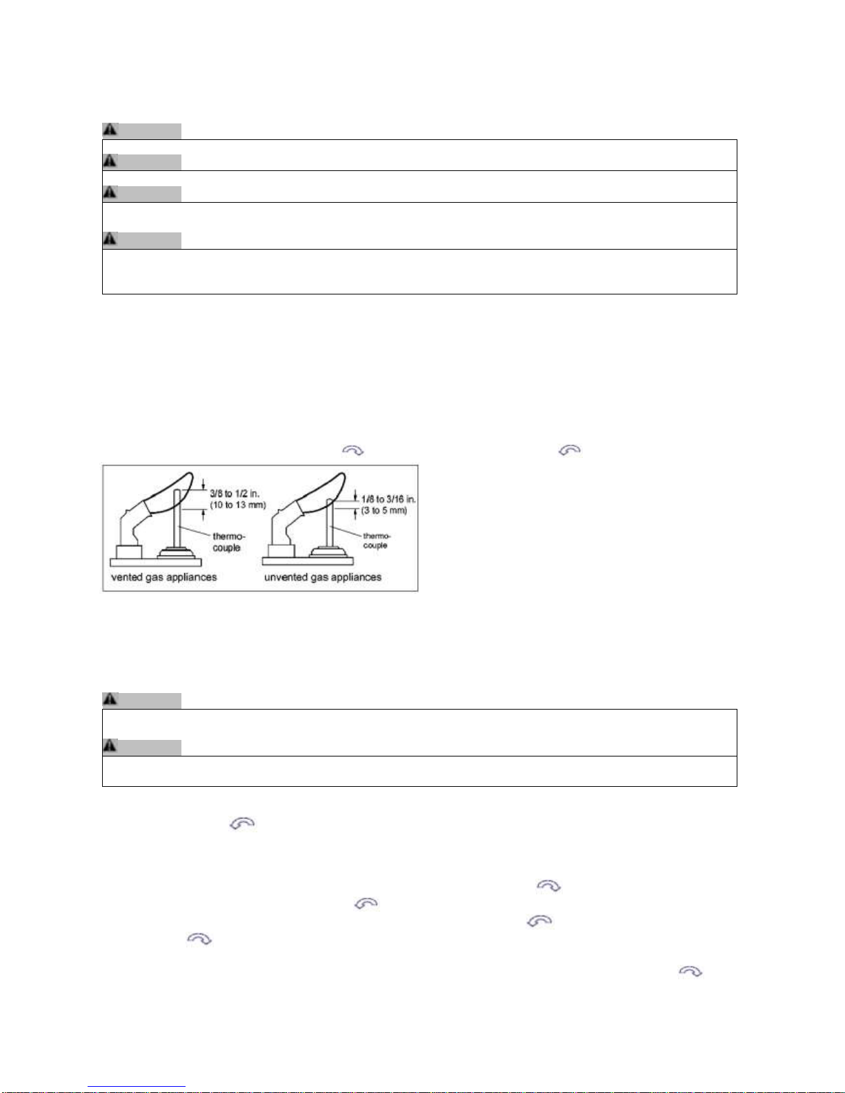
Pilot Flame adjustment
The pilot flow adjustment is pre-set to maximum at the factory. The pilot flame should envelope 3/8” to 1/2" of the
thermocouple – vented only (see fig.M5).
1. The adjustment screw can be reached through a hole in the MANUAL knob Figures 4 and 8).
2. Turn the MANUAL knob to the ON position.
3. It is now possible to pierce through the film on the cover with a screw driver to reach the adjustment screw
beneath.
4. Turn the adjustment screw clockwise to decrease or counterclockwise to increase pilot flame.
Fig.M5: Proper Flame Impingement on thermocouple
Outlet Pressure Adjustment
Pressure regulator or throttle are located under the cover and can be reached by removing the plug (see figures 4
and 6).
WARNING
Do not exceed the input rating stamped on the appliance nameplate, or the manufacturer’s recommended burner
orifice pressure for size orifice(s) used.
WARNING
For complete combustion, be sure the primary air supply to the main burner is adjusted properly. Following the
instructions of the appliance manufacturer.
1. Connect a pressure manometer to the valve outlet pressure tap. Pressure tap is opened by turning the screw
counterclockwise .
2. To access regulator adjustment remove plug first Figures 4 and 6).
3. Turn MANUAL knob and main valve knob to the ON position.
4. Turn pressure regulator adjustment screw, accessible through opening in top of cover, to set required
burner pressure (high fire). Pressure is increased by turning clockwise (pressure regulator models), or
decreased by turning counterclockwise .
NOTE: Throttle models pressure is increased by turning counterclockwise ; or decreased by turning
clockwise .
5. After adjustment, replace the plug.
6. If no other adjustments are required, close pressure tap(s) by turning the screw(s) full clockwise .
Check all connections/pressure tap(s) for leaks.

45
7. If the desired outlet pressure or flow cannot be achieved by adjusting the gas valve, check the gas valve
inlet pressure using a manometer at the valve inlet pressure tap. If the inlet pressure is in the normal
range, replace the gas valve; otherwise take the necessary steps to assure proper gas pressure to the
valve.
Minimum Gas Flow Adjustment (for CE Use only) (See fig. M4)
1. Set the control into low fire setting by turning the motor knob in OFF-position and back until the valve
opens.
2. The minimum rate can be set either by screwing in a calibrated minimum rate screw (fixed orifice) or an
adjustable minimum rate screw. Controls with adjustable screws without a customer specific setting are
factory set at maximum flow.
3. Turn the screw clockwise to decrease the minimum flow.
4. Care should be taken to screw the fixed orifice until it stops.
5. Close pressure tap(s) by turning the screw(s) full clockwise . Check all connections/pressure tap(s) for
leaks.
Fig.M6: Combination Control GV60, Cover
FINAL CHECK
Observe several complete cycles to ensure proper operation. During these cycles the electronics will determine
the optimum ignition sequence timing.
1. STOP! Read the safety information included before proceeding.
2. Turn main valve knob to the OFF, full clockwise position.
3. Place ON/OFF switch (if equipped) to the O (OFF position).
4. Wait five (5) minutes to clear out any gas. Verify that no gas is in the area around the appliance, including
near the floor. If you detect gas STOP! Follow “A” in the safety information of the Operating
Instructions. If no gas is present, proceed according to the Mertik Maxitrol Operating Instructions GV60OI-EN.
WARNING
Fire or explosion hazard. Attempted disassembly or repair can cause property damage, severe injury or
death. Do not disassemble the gas valve; it contains no serviceable components.

46
OPERATING INSTRUCTIONS - FOR OEM USE ONLY
WARNING
Fire or explosion hazard. Attempted disassembly or repair of controls can cause property damage, severe
injury or death. Do not disassemble the gas valve; it contains no serviceable components.
If the information in this manual is not followed exactly, a fire or explosion may result causing property
damage, personal injury or loss of life
A. BEFORE OPERATING verify that no gas is in the area around the appliance, including near the floor.
WHAT TO DO IF YOU SMELL GAS
Do not try to light any appliance.
Do not touch any electrical switch; do not use any phone in your building.
Immediately call the gas supplier from a neighbour’s phone. Follow the gas supplier’s instructions.
If you cannot reach the gas supplier, call the fire department.
B. Use only your hand to push in or turn the gas control knobs. Never use tools. If a knob will not push in
or turn by hand, don’t try to repair it, call a qualified service technician. Force or attempted repair may
result in a fire or explosion.
C. Do not use this control or any gas appliance if any part has been under water or in contact with water.
Immediately call a qualified service technician to replace the control system and any gas control which
has been under water or in contact with water.
D. These instructions are to be referenced as a user guide, and do not supersede appliance
manufacturer’s lighting instructions.
APPLICATION
GV60 is a battery-powered electronic remote ignition and control system for gas appliances with pilot
burners and ODS systems
Fig. M8 Combination Control GV60
Fig. M7 Combination Control GV60

47
GENERAL NOTES
Batteries – Remote Handset:
3 x 1.5V AAA (quality alkaline recommended)
Batteries – Receiver:
4 x 1.5V “AA” (quality alkaline recommended)
An AC Mains Adapter may be used instead of batteries (only the Mertik Maxitrol AC Mains Adapter or one
approved by Mertik Maxitrol can be used).
NOTE: During a power outage the AC Mains Adapter must be unplugged from the receiver to operate in the
battery mode.
TO TURN OFF APPLIANCE
Press button on remote handset.
NOTE: Press (down arrow) to turn main gas to pilot gas.
Remote Handset (see figure M9)
Simultaneously press and hold (star) and (up arrow) until a short acoustic signal confirms the start
sequence has begun; release buttons.
Continuing signals confirm the ignition is in process.
Once pilot ignition is confirmed, there is main gas flow.
NOTE: If the pilot does not stay lit after several tries, turn the main valve knob to off and follow the
instructions “Turn Off Gas to Appliance”.
Fig.M9 Remote Handset
Remote Handset (see fig. M9)
To increase flame height press and hold the (up arrow) button.
Press (down arrow) to decrease flame height or to set appliance at pilot flame.
For fine adjustment tap the large flame or small flame.
NOTE: If the appliance will not operate, follow the instructions “TURN OFF GAS TO APPLIANCE”.
With very low battery the GV60 system shuts off the fire completely. This will not happen if the
power supply is interrupted.
Battery Replacement
Battery replacement is recommended at the beginning of each heating season. Do not use metal tools to
remove batteries. Using a metal tool could cause a short that may damage the receiver.

48
Fig.M10

49
10. Commissioning the Fire Unit
Check the gas supply and gas appliance for soundness.
The appliance must be fully fitted; the glass on the appliance must be sealed.
Check that there is no movement of the glass or gaps in the seal.
Check that all the products of combustion are entering the flue and that no products of
combustion are entering the building
Lighting the appliance for the first time.
IMPORTANT NOTE - Do not run the appliance if the glass has been removed or
damaged.
When lighting the appliance for the first time, the materials (i.e. paint, sealants etc.) will give off
smoke and an unpleasant odour. This is quite normal and will disappear after a few hours.
During this period, keep the room well ventilated.
Check that all available functions work correctly.
(See ‘Lighting the appliance’ in User Instructions for information).
Light the fire on maximum and run for at least 30mins before turning the appliance to low rate.
NOTE – The flames will start off blue until the appliance has heated properly before turning
more yellow.
Spillage Test
A spillage check must be completed.
The spillage test is intended to check the draw in the chimney. The spillage test can only
performed if the appliance is fully installed including the fitment of the Frame.
Close all doors and windows of the room in which the appliance has been installed.
Testing is to be done with the appliance on ‘high’ rate and has been running for at least 20
minutes.
Check the appliance for spillage using a smoke match, fitting it into the holder provided (see fig
121).
Fig. 121

50
Important Note – The Frame must be fitted before testing for spillage.
Position the lit match 50mm in from the front and 50mm right of the left bottom corner of the air
intake (see fig. 122).
Fig. 122
If the appliance and chimney is functioning correctly all smoke should be drawn into the air
intake and out of the room.
If the smoke doesn’t get drawn in the appliance then the restrictor plate can be adjusted.
Adjusting the Restrictor Plate
Important
The restrictor plate is set to the maximum efficiency position; if the appliance spills, adjust the
restrictor using the hex key (see fig. 123) turning counter-clockwise to increase the aperture in
the flue spigot (see fig. 124)
Fig. 123 Fig. 124
Adjustable Restrictor
If the smoke continues to spill then the unit is to be disconnected and expert advice taken.

51
Flame stability
IMPORTANT NOTE - The appliance should always be observed when lighting. On starting the
appliance an acoustic signal confirms the ignition is in process once the acoustic signal stops
the main valve opens to ‘High rate’ to allow gas through to the main burner. All of the main
burner should light within 6 seconds lighting the whole burner area.
If this does not happen then the appliance should be turned off allowing 5
minutes before attempting to relight.
Check the stability of the flame by turning to low rate then back to high rate then to low rate
doing this around three times whilst observing the stability of the main burner and pilot flame,
there should be no problems lighting the main burner.
Aeration
IMPORTANT NOTE – The appliance aeration is factory set and under NO circumstances be
adjusted by the installer (see fig. 125, 126).
Fig. 125
Fig. 126

52
11. Briefing & Handover to the Customer
Instruct the customer on the full operation of the appliance.
Warn the customer that the fire unit may give off a temporary odour; this is normal running in of
the unit, and will disappear after a short period of use.
Inform the user that the appliance glass is only to be removed when servicing, and not to
disturb or place items on the fire bed as this may disturb the combustion.
Inform the customer that it is recommended that a full service on the appliance and flue checks
be carried out annually by competent person/s.
Caution - Make the user aware of the location of the isolation valve and tell the user to close
the isolation immediately in case of malfunction / bad performance and to contact the installer
in order to prevent dangerous situations.
The appliance is equipped with a sensor to monitor the function of the flue (TTB Switch) If the
evacuation of the combustion products is interrupted (caused by lack of flue pull or blockage),
the TTB will operate and shut the appliance off. If for any reason the fire does shut off, allow at
least 5 minutes to elapse before attempting to relight as described in the “lighting instructions”
section, on pages 65-69. If the appliance repeatedly shuts off after being re-started (as detailed
in the ‘Lighting instructions’ section), a GAS SAFE registered engineer should be contacted to
examine the appliance and installation.
Inform the user to always observe the appliance when lighting, once the acoustic signal stops
the main valve then opens to ‘High rate’ allowing gas through to the main burner. The main
burner should then light within 6 seconds if this does not happen then the appliance
should be turned off allowing 5 minutes before attempting to relight.
Warn the user of the following points
not to block vents and to check regularly and remove any blockages.
not to block the air intake on the appliance.
that all parts of the appliance will become hot while the appliance is running, so it is
recommended that a guard conforming to BS8423: 2002 be used for the protection of
young children, aged or infirm persons.
not to stand too close to the appliance for prolonged periods of time; loose clothing is
particularly at risk of burning, and that rubbish cannot be burned in the unit.
against placing combustible material directly in front of the appliance. Floor coverings,
such as carpets, are considered to be acceptable.
Ensure the installer details are filled in.
Hand over the installation manual to the customer.

53
12. Servicing & Maintenance
It is advised that the appliance is serviced annually by a qualified person to Local and National
Regulations.
Only carry out maintenance work when the appliance is cold.
Exchangeable Components List
Pilot unit Seagas P4-41
Injector Injector marked 1.8 (1x1.8mm)
Control Valve GV60
Controls Box Radio Frequency
TTB CH L120C fitted to GFL850Urn
Annual Maintenance.
Safety precautions must be taken when cleaning the appliance.
Ensure the appliance is cold before carrying out a service.
Isolate the appliance and disconnect the unit.
Always test for gas soundness and spillage after refitting the appliance.
Check the fire bed, pilot burner/ignition unit, for soot or debris deposits.
Replace all misplaced parts and retest.
On the failure of pilot burner/ignition or control valve, have the repairs carried out by a
competent person.
Inspecting the Flue / Chimney
The appliance must be serviced by a qualified person in accordance with local and national
regulations.
An inspection of the flue / chimney must be carried out on an annual basis or if the appliance is
suspected that it is not expelling the emissions correctly.
Check the effectiveness of the flue by carrying out a spillage check as shown on pages 49-51.
If the appliance fails, a further inspection of the flue must be carried out.
NOTE – To access the flue/chimney the appliance must be isolated and the burner assembly
and inner casing removed.
Remove any debris such as soot, masonry etc.
If there are excessive amounts of debris the outer casing must be removed to clean the void
around the appliance.
A spillage test must be carried out once the appliance has been fully reinstalled (see pages 49-
51).

54
Replacing the Glass Seal
The glass seal is a perishable item and at some point may need changing.
If the glass seal is frayed and starting to leak emissions then it must be replaced.
The seal is available from most Chesney’s suppliers.
Observe the old seal placement before removing, taking note of the top edge.
Remove the old seal and clean off any dirt and old adhesive. Start from the bottom centre of
the appliance (fig. 127) carefully adhere the seal around the edges then stick part of the seal on
the lip across the top edge then press the seal into the fold (shown in fig. 128 below right) to
ensure a good seal.
Fig. 127 Fig. 128
Replacing the RF receiver control box
Carefully remove the burner and burner base to access the RF receiver control box remove the
remaining wiring, undo the securing clip (fig. 129) lift the lever out of the reset button hole then
remove the box out of the tabs on the bracket (fig. 130-132)
Fig. 129 Fig. 130
Fig. 131 Fig. 132
Refit a genuine replacement RF controls box
IMPORTANT - When refitting ensure the controls box is fitted in the tabs, secured down and
the lever tip located in the reset button hole.

55
Replacing the ON/OFF switch (Fig. 133)
Carefully remove the burner and burner base to access the wiring for the ON/OFF switch.
Disconnect the power supply (Fig.137). Remove the screw on the ON/OFF switch bracket
(Fig.134, 135).
Slide out the ON/OFF switch out of the holder (Fig.136). Disconnect the switch lead from the
controls box and release the spade connector from the interrupter block (Fig.138-140).
Fig. 133 Fig. 134
Fig. 135 Fig. 136
Fig. 137 Fig. 138
Fig. 139 Fig. 140
Only replace with genuine parts refitting in the reverse order.

56
Pilot Removal
Work should only be carried out by a competent person and all gas work be carried out by a
qualified person in accordance with national and local regulations.
The pilot to be exchanged must be a genuine like for like part (see fig. 141 and 142)
Fig. 141 Fig. 142
Part – Seagas P4-41 Marking P441
Ensure the appliance is cold before commencing work.
Remove the glass.
Isolate the appliance and remove the urn, burner and Rimex base.
Disconnect the main 8mm gas supply pipe from the test point, the battery extension lead and
disconnect the wiring attached to the burner assembly.
Remove the pilot bracket screws (see fig. 143) Remove the spark lead (see fig. 144)
Fig. 143 Fig. 144
Undo the 4mm pipe with a 10mm spanner (see fig. 145) and disconnect from the pilot.
Remove the bracket (see fig. 146).
Fig. 145 Fig. 146

57
Disconnect the thermocouple nut from the interrupter block at the rear of the control valve
freeing the pilot (see fig. 147).
Fig. 147
Only replace with genuine parts refitting in the reverse order.
Test for soundness on all gas connection joints.
Check Spillage.
Commission the appliance.
Control Valve Removal – Mertik GV60 (fully remote controlled)
Important Note – Replace with a genuine Chesney’s set valve, the valve must be purchased
from a Chesney’s supplier as the valve’s ‘high rate’ and ‘low rate’ screws must be set.
Work should only be carried out by a competent person and all gas work must be carried out by
a Gas Safe Registered person in accordance with national and local regulations.
Ensure the appliance is cold before commencing work.
Remove the glass.
Isolate the appliance.
Remove the urn and burner then lift the burner base
Disconnect the main 8mm gas supply pipe from the test point (see page 29)
Disconnect the battery extension lead (see page 29-30) and disconnect the wiring attached to
the burner assembly.
GV60 Valve
Fig. 148 Fig. 149

58
Remove the attachment screws (see fig. 150) Undo the pipework and remove
the interrupter block (see fig. 151).
Fig. 150 Fig. 151
Disconnect the 8 wire cable (see fig.152)
Fig. 152
Only replace with genuine parts refitting in the reverse order.
Test soundness of all gas connection joints.
Check Spillage.
Commission the appliance.

59
Removing the Injector
Work should only be carried out by a competent person and all gas work must be carried out by
a Gas Safe Registered person in accordance with national and local regulations.
Ensure the appliance is cold before commencing work.
Remove the glass.
Isolate the appliance and remove the urn, burner and Rimex base.
Lift the burner base.
Disconnect the main 8mm gas supply pipe from the test point (see page 29)
Disconnect the battery extension lead (see page 29-30) and disconnect the wiring attached to
the burner assembly.
Lift the burner base clear from the appliance. Disconnect the flexi tube using a 15mm spanner
(see fig. 153) and remove both screws on either side of the injector (see fig. 154) to release the
injector and bracket.
Fig. 153 Fig 154
Remove the injector nut using a 13mm spanner (see fig. 155). NG Elbow Injector has a single
hole markings are located on the nozzle (see fig. 156)
Fig. 155 Fig. 156
Only replace with genuine parts refitting in the reverse order.
Test soundness of all gas connection joints.
Check Spillage.
Commission the appliance.

60
Removing the Panels
IMPORTANT NOTE – The burner assembly can only be removed by a qualified engineer.
Ensure the appliance is cold before commencing work.
Remove the glass (For glass removal see pages 15 & 16).
Remove the urn, burner and burner base assembly.
Remove the panel bracket and screw (see fig. 157) to release the side panel (see fig. 158)
Fig. 157 Fig. 158
Remove the back panel (see fig. 159).
Fig. 159
Remove the panel bracket and screw on the other side then lift the side panel out (see fig.160,
161).
Fig. 160 Fig. 161
Only replace with genuine parts refitting in the reverse order.
Test soundness of all gas connection joints.
Check Spillage.
Commission the appliance.

61
Replacement of the TTB Heat sensor
IMPORTANT – The TTB must NOT be by-passed or put out of action.
TTB CH L120C fitted to GFL850Urn
Remove the urn and burner.
Remove the panels.
Behind the back panel is an access point to the TTB sensor (see fig. 162). Undo the 4 screws.
Remove the TTB connections (see fig. 163). Remove the TTB via the screws (see fig. 164).
Fig. 162 Fig. 163
Fig. 164
Only replace with genuine parts refitting in the reverse order.

62
13. Fault Finding
Symptom
Check List
Unit does not respond.
Check Remote is working properly
Check Battery power supply.
Check wiring is correct.
Remote does not work.
Check Battery Power.
Check aerial connection.
Ensure the handset is paired
Hardwire switch does
not work. (If fitted)
Check Switch is wired properly.
Unit clicks but no spark
or weak spark.
Check spark lead is connected properly.
Check spark electrode is in the correct area and the gap correctly
distanced.
Check spark lead is not arcing on other parts of the appliance
Unit sparks but does not
light pilot.
Check for a good spark.
Check the spark is in the correct area.
Check if the ventilation is not too strong.
Check if there is gas running through.
If there is no gas.
Check isolation tap/shut off valves are free from grease.
Check isolation tap/shut off valve/s are on.
Check for blockages.
If there is gas but pilot
does not light
Check pressure is correct.
Check for blockages.
Check for draughts.
Check the pilot gas slots are clear.
Check for a clear spark
Pilot lights but does not
light main burner
Check the pilot flame is heating the thermocouple.
Check the thermocouple nut is properly tightened into the interrupter block.
Check that the pilot lights early on ignition clicks.
Check ventilation is not too strong.
Check TTB connections
Check TTB for fault. IMPORTANT – Only bypass to check if TTB is faulty
the appliance TTB must NOT be left out of action.
Burner lights but turns
off after a few minutes
Check thermocouple nut is properly secured to the interrupter block.
Check ventilation is not too strong and the flame is not blowing off the
thermocouple.
Check gas pressure is correct.
Check pilot and burner flame stability
The GV60 fully remote controlled system has audible beeps to indicate a problem with the system.
Reason
No Beep
Impulse magnet not operating properly – Replace gas valve
1 Long Beep
ON (1)/OFF(0) Switch is on OFF position – Switch to ON (1)
3 Short Beeps
Low Batteries – Replace receiver batteries with 4x1.5V “AA” quality alkaline
batteries

63
14. User Instructions
General
The flue must be fitted in accordance with Local and National Regulations.
The flue must not be shared with any other appliance.
It is advised that flue specialist inspect the flue system on an annual basis to ensure that
the flue system is sound and the combustion products outlet (terminal) is clear of
obstruction.
It is highly recommended that a full service on the appliance be carried out annually by
competent person/s.
The gas connection must be in accordance with Local and National Regulations.
Installation and servicing must be carried out by a competent person in line with relevant
regulations.
WARNING – Do not use the appliance if the glass is broken, removed or is open.
Do not to block the air intake on the appliance.
Do not make changes to the appliance.
All parts of the appliance will become hot while the appliance is running, so it is recommended
that a guard conforming to BS8423: 2002 be used for the protection of young children (i.e. in
nurseries), aged or infirm persons.
Do not leave children and persons who cannot judge the consequences of their actions alone
with a burning appliance and place the remote control out of reach.
Allow adequate clearances for curtains, pictures, soft furnishings, electrical appliances or any
items that may get damaged through heat.
Curtains should not be positioned above the appliance.
Blown vinyl wall paper or coverings must not be used on the chimney breast where the
appliance is fitted.
All parts of the appliance become hot while running and should therefore be considered to be a
working surface.
It is also advised against placing combustible materials or soft furnishings directly in front or
above the appliance. Floor coverings, such as carpets (up to the hearth), are considered to be
acceptable.
Debris from any source, or soot formed, should be removed from time to time.

64
The appliance is equipped with a sensor to monitor the function of the flue (TTB Switch) If the
evacuation of the combustion products is interrupted (caused by lack of flue pull or blockage),
the TTB will operate and shut the appliance off. If for any reason the fire does shut off, allow at
least 5 minutes to elapse before attempting to relight as described in the “lighting instructions”
section, on pages 65-69. If the appliance repeatedly shuts off after being re-started (as detailed
in the ‘Lighting instructions’ section), a GAS SAFE registered engineer should be contacted to
examine the appliance and installation.
Ventilation – GB appliances over 7kW (net) requires permanent ventilation and should be
fitted in accordance with BS 5440-2 and must be checked on a regular basis to ensure there is
no obstruction.
The appliance when lit from cold will start off with a blue flame and will gradually turn more
yellow as the flue, and appliance heat up.
Important Notes
The appliance must only to be opened for maintenance.
The appliance must not be operated if the appliance glass is open, broken or has been
removed.
The appliance should always be observed when lighting.
Improper installation, service, maintenance, adjustment or
alterations may cause injury or property damage
Do not disturb or place anything on the fire base as this will affect combustion.
Do not operate the appliance if any part of the appliance is damaged
The appliance must be installed and maintained by a suitably qualified heating
engineer.
Ensure this manual remains with the appliance.
This appliance is manufactured byChesney’s Limited
194 – 200 Battersea Park Road
London
SW11 4ND
Tel: 020 7627 1410
Fax: 020 7622 1078

65
Lighting the Appliance
Check the On/Off switch is on (I) (see fig. 165)
Fig. 165
On/Off Switch
The GV60 is fully remote controlled.
IMPORTANT NOTE - The appliance should always be observed when lighting.
If the appliance makes a long beep when starting the appliance then the on/off switch is set on
the OFF (O) position, switch the unit to the ON (I) position.
Note - If the handset is out of action or is not obtainable the appliance can be turned off by
pressing the ON/OFF switch to the OFF (O) position (located on the left side of the appliance).
Care must be taken when doing this as the appliance will be hot.
Remote Control
The appliance’s standard functions such as ignitions, controlling the flame height, standby (pilot
burner) position and switching off are performed in the MAN position, the manual control of the
remote control
In addition, the remote control can also be used to set a number of additional functions:
Temperature display in degrees Celsius or Fahrenheit
Time
Thermostat function
Timer for thermostat function
Caution - Although highly improbable, we cannot rule out that your appliance’s ignition process
can be started unintentionally through other remote controls. For example the remote control of
your neighbours’ gas heater, but also car keys and garage door openers. The result will be that
your appliance will burn when you do not want it to.
Unintended ignition of your appliance could be solved or prevented by turning the ON/OFF
switch or closing the gas tap near your appliance. This is the safest precaution if the appliance
is not is use for long periods to turn the ON/OFF switch to the OFF position and to close the
gas tap near your appliance.

66
Briefly pressing the SET button will go through the following functions:
MAN -> TEMP -> TEMP -> (P*) TIMER -> MAN
Where, depending on the timer setting
(P*) is displayed as P1 , P1 , P2 , P2
NOTE – To go back to the MAN position press the up or down arrow.
Caution When pressing the buttons (with the exception of the SET button) the transmission
symbol ( ) will appear to indicate that the transmission is taking place between the remote
control and the receiver.
The receiver acknowledges the transmission with a sound signal.
The appliance will automatically enter the standby position, if there is no transmission for 6
hours.
Set the remote control to the MAN position.
To light the appliance you must press and hold both buttons ON and Up arrow button
(see fig. 166) until a short acoustic signal is heard, this confirms that the starting sequence has
begun; release the buttons. Continuing signals confirms the ignition is in process.
Fig. 166
The pilot (flame supervision device actuating flame) will light soon after the appliance has been
activated and can be observed in the area shown below. (See fig. 167).
Fig. 167

67
If for any reason the fire does shut off, allow at least 5 minutes to elapse before attempting to
relight. If the appliance repeatedly shuts off after being re-started a GAS SAFE registered
engineer should be contacted to examine the appliance and installation.
The appliance will then light on High rate; if the appliance is cold it is advised to leave the
burner on high rate for at least 20 minutes to warm up the flue before turning between the ‘High
and Low rates.
When the appliance has warmed the flame height can be adjusted between ‘High and Low’ by
pressing and holding the ‘Up Arrow’ button to increase flame, or pressing and holding the
‘Down Arrow’ button to decrease flame height.
The pilot can just remain lit this is done by holding the ‘Down Arrow’ button until the
appliance turns off the main burner.
To go from the lit pilot to main, press and hold the ‘Up Arrow’ button.
To turn off the fire unit completely press the button.
Restarting the Appliance
If the fire is extinguished or goes out in use, allow 5 minutes before attempting to restart
following the lighting sequence.
If the fire shuts itself off repeatedly, do not use the fire, and have the flue and fire checked by a
suitably qualified person.
If the appliance is not lighting after 4 ignition attempts, close the gas tap and call the installer.
Close the gas tap in case of malfunctions and / or poor operation and warn the installer.
Temperature Display
The room temperature can be indicated on the display in degrees Celsius (°C) using a 24 hour
clock or degrees Fahrenheit (°F) using a 12 hour clock.
Simultaneously press OFF and the ’Down button’, until the correct display appears.
Time
The display can indicate time.
After placing the battery or simultaneously pressing ‘Up button’ and the ‘Down button’ the
time indication will flash on the display and you will be able to adjust the time.
Simultaneously press ‘Up button’ and the ‘Down button’ until the time indication
flashes on the display.
Press the button ‘Up button’ to set the hours.
Press the button ‘Down button’ to set the minutes.
Press OFF to return o the MAN position, or wait for the system to automatically
return to the MAN position.

68
Thermostat Function
Using the thermostat function you can set two temperatures, which can be controlled
thermostatically.
These temperatures are referred to as day temperature and night temperature.
The TEMP and TEMP symbols on the display refer to day and night temperature
respectively.
The room temperature is compared to the set day/night temperature and then the flame height
is automatically controlled in order to reach the set temperature.
To be able to use the day/night temperature function, the appliance must be in the standby
position.
Caution When using the thermostatic function always leave the remote control in a suitable
area so that the thermostat is able to sense the ambient room temperature taking note of
influences such as draught, heat from radiators, direct sunlight.
Setting Day/Night Temperature
By pressing the SET button the functions are as follows:
MAN -> TEMP -> TEMP -> (p*) TIMER -> MAN
Briefly press the SET button to enter the TEMP or the TEMP position.
Press the SET button until the temperature on the display flashes.
Set the required temperature by using the button ‘Up button’ and the ‘Down button’.
Caution The minimum temperature is 5°C/ 40°F
Control of the night temperature is switched off by lowering the temperature until two dashes ‘—
‘appear on the display.
Press the OFF button or wait until position TEMP or TEMP appears on the display.
Activating the Thermostat Function
For activating the thermostat function, you must proceed with the following steps.
Place the appliance in the standby pilot burner position using the ‘Down button’
Set the day/night temperature
Choose the TEMP or TEMP function using the SET button.
Timer For Thermostat Function
The default settings are as follows:
Program 1 (P1): P1: 6.00am P1 : 8.00am
Program 2 (P2): P2: 4.00pm P2 : 10.00pm
The appliance must be in the standby position in order to be controlled by the timer.
Setting Times for the Timer
To set the timer, proceed as follows:
Set the day and night temperature as described above
Briefly press the SET button to enter the (P*) TIMER position.
Hold the SET button until P1 is displayed and the time flashes.
Set the time of P1 using the Up button and the Down button.

69
Press again to set the off time P1 using the Up button and the Down button.
Press again to set the P2 using the Up button and the Down button.
Press again to set the off time P2 using the Up button and the Down button.
Press the OFF button or wait until position (P*) TIMER appears on the display to
save your changes.
Activating the Timer Function
Follow the steps below for activating the timer control:-
Place the appliance in the standby (pilot burner) position using the Down button
Set the day/night temperature if you have not yet done so.
Choose the (P*) TIIMER function using the SET button.
Automatic Turn Down
6 Hours No Communication Function (CE & CSA Versions)
Manual Mode / Temperature / Timer Mode: The valve will turn to pilot flame if the batteries in
the handset are low or if the handset is out of communication range for a 6 hour period.
6 Hour No Communication Function (CSA Version)
Manual Mode / Temperature / Timer Mode: The valve will turn to pilot flame if there is no
change in flame height for a 6 hour period. In Temperature / Timer Mode if the ambient room
temperatures changes, the flame height will adjust automatically to maintain set temperature,
and the fire will continue to function normally. The valve will turn to pilot flame if the set
temperature and the ambient room temperature remain the same over a 6 hour period.
Receiver Overheating (For Module Versions only)
Valve turns to pilot flame if the temperature in the receiver is higher than 140°F (60°C). The
main burner will come back on only when the temperature is below 140°F (60°C).
1 Hour Turn Down For Special Receiver (Bedroom Fireplaces Only)
The valve will turn to pilot flame if there is no change in flame height over a 1 hour period.
AUTOMATIC SHUT OFF
Low Battery Receiver
With low battery power in the receiver the system shuts off the fire completely. This will not
happen if the power supply is interrupted.
Five Day Shut Off (CSA Version)
The system shuts off the fire completely if there is no change in flame height for 5 days.

70
Changing the Batteries
The batteries will require changing yearly (based on the average usage) this may differ
depending on usage and on the quality of battery, the battery change is best done on the
annual service of the appliance.
However if the appliance is showing signs of diminishing signal or during the lighting sequence
then the batteries may need changing.
Firstly replace the handset battery before attempting to change the fire unit battery
(see fig. 168)
Remote Handset Battery Fig. 168
3 x 1.5V AAA
(Quality alkaline recommended)
Receiver Batteries
4 x 1.5V “AA”
(Quality alkaline recommended)
If the batteries are running low you will hear 3 short beeps from the control box.
Ensure the appliance is cold.
The battery compartment is located in the base of the appliance on the right side (see fig. 169)
pull the ribbon to retrieve the battery holder (see fig. 170) remove the screw and replace the
batteries in the directions indicated in the compartment (see fig. 171, 172).
Check the connections are secure before replacing the box back in the appliance.
Fig. 169 Fig. 170
Fig. 171 Fig. 172

71
Resetting the Appliance
IMPORTANT – Ensure the appliance is cold.
If the appliance is functioning incorrectly the reset button on the controls box can be reset by
pushing down the lever then releasing as soon as a beep has been heard (do not hold) (see
fig. 173).
This will then reset the system.
Fig. 173
Cleaning
Cleaning should only be carried out when the fire is turned off and cold.
This appliance contains no asbestos.
Cleaning Paintwork
Use a clean soft dry brush to remove dirt and debris from the appliance.
If the appliance has ingrained dirt use soapy water to dampen a soft cloth and use to clean.
Cleaning Glass
The glass is specially formulated to withstand very high temperatures use a mild glass cleaner.
Use a soft cloth to avoid scratches that may weaken the glass.
Follow instructions for removing the glass.
Important Notes
Ensure the appliance is cold.
Care must be taken when using the allen key to prevent damage to paintwork.
Ensure the glass is clean on both sides as dirt; oils etcetera can etch the glass.
Do not clean with abrasive materials as this can accelerate dirt accumulation and
weaken the glass.
Ensure the glass is fitted correctly to avoid spillage.
Check spillage after carrying out work.
The glass may collect a white powdery residue on the inside of the glass this is a combination
of minerals and acids in the gas.
It is known the longer left on the glass the harder it is to remove. It is recommended to use
‘White Off’ by Rutland or ‘Brasso’ following the directions specified on the bottle. This can be
purchased from fireplace companies / hardware supplies.

72
Burner Bed
For removing the glass please read instructions on pages 15-16 for refitting pages 31-32
for securing the glass.
NOTE – The burner bed material used to spread the flame can irritate the skin when handled
and is advised to wear suitable safety equipment when cleaning products inside the appliance.
It is advised to wear protective gloves and a dust mask conforming to EN 149:2001+A1:2009
FFP3 (available from most DIY shops).
It is necessary to clean the fire if debris or soot deposits have accumulated. Use a soft brush to
clean the burner top.
IMPORTANT NOTE - The material used on the burner bed is extremely fragile; care must to be
taken when handling this product to avoid damage. Warning - Do NOT use a vacuum to clean
the burner bed.
It is advised that an experienced Chesney’s approved person replace the material.
Only use genuine Chesney’s parts.

73
15. Installer Check List
Flue Checklist
PASS
FAIL
Flue Size
Flow test
Spillage test
Gas Checklist
PASS
FAIL
Soundness
Standing Pressure
Working Pressure
Ventilation
PASS
FAIL
Ventilation requirements for appliance
16. Dealer and Installer Information
Dealer and Installer Information
Dealer
Installation Company
Contact No.
Gas Safe Registered Engineer
Date of Purchase
Contact No.
Model No.
Gas Safe Register No.
Serial No.
Date of Installation
Gas Type

74
17. Annual Service Record
Annual service record
Year 1
Gas Safe Registered Engineer
Contact No.
Gas Safe Register No.
Date of Service
Annual service record
Year 2
Gas Safe Registered Engineer
Contact No.
Gas Safe Register No.
Date of Service
Annual service record
Year 3
Gas Safe Registered Engineer
Contact No.
Gas Safe Register No.
Date of Service
Annual service record
Year 4
Gas Safe Registered Engineer
Contact No.
Gas Safe Register No.
Date of Service
Annual service record
Year 5
Gas Safe Registered Engineer
Contact No.
Gas Safe Register No.
Date of Service
Annual service record
Year 6
Gas Safe Registered Engineer
Contact No.
Gas Safe Register No.
Date of Service
The following information supplied in this manual is correct at the time of publish;
Date of last manual update 05th August 2013. Print V1
 Loading...