


0

1
Decorative Fuel Effect Appliances
Technical Manual
PIN: 0558BS5932
User and Installation Instructions
Chesney’s Universal Basket Burner18”
Burner Code: CUBB18
Available in Natural Gas or LPG.
NOTE –
Chesney’s 5 piece large log set are for Natural Gas Models only
Chesney’s 12 piece small log set are for LPG Models only

2
Contents
Section
Pages
1
Unpacking / Unit Parts
3 2
Technical Data
4 3
Installation Parameters
5-6 4
Installation
7-9 5
Burner Information
10-31 6
Clay
Granules
32 7
Fibre coal / Log placement
33-39 8
Commissioning the fire unit
40 9
Briefing and handover to the customer
41 10
Servicing
42-45 11
Fault finding
46 12
User Instructions
47-56 Fireguards
47 Lighting the appliance
49-54 Changing th
e Batteries
55 Cleaning
56 13
Installer checklist
57 14
Dealer and Installer Information
57 Annual Service Record
58

3
1. Unpacking
Remove the appliance from its packaging, and check that it is complete and
undamaged.
If satisfied by the condition and the contents is as specified, proceed with the
installation.
The installation should only be carried out by a competent person and all gas work
must be carried out by a Gas Safe Registered person in accordance with national
and local regulations for both gas and electricity (If required).
The installation must comply with local and national building regulations.
For the Republic of Ireland, reference should be made to IS813 and ICP3 and any
guidance notes from Bord Gais.
Failure to comply with the regulations nullifies ALL guarantees.
Unit Parts
NG Logs (If supplied) Embers (If supplied Clay Granules Coals 2x Bags
with NG Logs) 1kg bag (If supplied)
LPG Logs
(If supplied)

4
2. Technical Data
Specifications for CUBB18
Oxypilot Assembly Marking
Natural Gas Burner : NG 9057, LPG Burner
– LPG 9221
Gas Connection Size
8.0mm O.D. tubing
Minimum Flue Diameter (Millimetres/Inc
hes) 178.0/7.0
Minimum Flue Height (metres)
3.0 Appliance Mass (kilograms)
3.6
Gas
Type
Gas Category, Type
And Supply Pressure
Countries of Destination
AT
BE
CH
CY
CZ
DE
DK
EE
ES
FI
FR
GB
GR
HU
IE
IT
LT
NG
I
2H - G20 at 20mbar
I
2E - G20 at 20mbar
I
2E+ - G20G25at2025mbar
LPG
I
3P - G31 at 37mbar
I
3+ - G30G31 at 28-3037mbar
I
3B/P – G30G31 at 30mbar
Gas
Type
Gas Category, Type
And Supply Pressure
Countries of Destination
LU
LV
NL
NO
PL
PT
RO
SE
Sl
SK
TR
NG
I
2H - G20 at 20mbar
I
2E - G20 at 20mbar
LPG
I
3P - G31 at 37mbar
I
3+ - G30G31 at 28-3037mbar
I
3B/P – G30G31 at 30mbar
Gas
Type
Gas Category, Type
And Supply Pressure
Injector
(1 per appliance)
Heat Input
kW, Gross
(High / Low)
Burner Pressure
(Hot) mbar
(High/Low)
Marking Size
Remote (GV30/GV60)
NG
I2H - G20 at 20mbar 180
Multiholed
7x1.8mm
13.0/7.4 3.8/1.6
I2E - G20 at 20mbar 180
Multiholed
7x1.8mm
13.0/7.4 3.8/1.6
I2E+ - G20G25at2025mbar 180
Multiholed
7x1.8mm
13.0/7.4 3.8/1.6
LPG
I3P - G31 at 37mbar
18S
Single Hole
1.8mm
11.0/8.2 24.6/14.6
I3+ - G30G31 at 28-3037mbar
18S
Single Hole
1.8mm
11.0/8.2
19.0/11.3 (G30)
24.6/14.6 (G31)
I3B/P – G30G31 at 30mbar
18S
Single Hole
1.8mm
11.0/8.2 19.0/11.3
Recommended Opening Size
Model
Height Width
CUBB18
[NG]
580mm 580mm
CUBB18
[LPG]
545mm 580mm
NOTE – Other types of larger flue/opening size combinations (and canopies) can
be used provided that the combustion products are cleared. If in doubt contact a
flue specialist for advice.

5
3. Installation Parameters
The fire unit must be installed and used in accordance with these
instructions.
This appliance is for decorative purposes.
For your safety it is law that all gas appliances must be installed by a
competent person, in accordance with the current gas safety
regulations applicable in the country of use.
The installation must be carried out in accordance with the relevant
local and national specifications and comply with building regulations.
The following must comply with the requirements and satisfy Building
Regulations – Approved Document J.
Builders opening and Fire Chamber must be constructed of
non-combustible material
Hearth and clearance dimensions
The minimum flue opening is 178mm (7”) diameter 250 sq.
cm. (38.5 sq. inches) and a minimum height of 3m (10ft),
provided the flue which serves this appliance.
An in-line fan that complies with BS 5440: Part 1 can be used to
improve flue draught.
NOTE - The flue must not be shared with any other appliance.
Prior to installation, ensure the compliance of local distribution
conditions (E.g. The type of gas, pressure and the adjustment of the
appliance) are compatible.
The builder's opening or fireplace opening must be constructed of a
non-combustible material.
Before the fire is installed, the chimney should be swept and a flue
test in accordance with National Regulations should be carried out.
The flue must be fitted in accordance with National Regulations,
damper plates or flue restrictors must be removed or fixed
permanently in the fully open position.
The gas connection must be in accordance with National Regulations.
The pilot light and flame sensing system fitted to this fire is also an
atmosphere sensing device, this is not adjustable and must not be put
out of action. If the pilot light is damaged or faulty it should be replaced
only with the original identical unit supplied by Chesney’s Limited.
The room where the appliance is to be fitted must have a permanent
air vent with a minimum effective area of 100cm sq. to the outside air
in accordance with National Regulations and must be checked on a
regular basis to ensure there is no obstruction.

6
This appliance must not be fitted in any room where steam is present
(e.g. Bathroom).
The appliance is not fitted with an integral guard. It is recommended
that a guard be used for the protection of young children, the elderly or
infirm and also for normal use conforming to BS8423:2002, such that
access to the flame is minimised.
It is advised not to stand too close to the appliance for prolonged
periods of time; loose clothing is particularly at risk of burning due to
the presence of an unguarded flame.
It is also advised against placing combustible materials directly in front
of the appliance. Floor coverings, such as carpets, are considered to
be acceptable.
Due to the newness of materials, the fire may give off a slight smell for
a period of time after commissioning. This is quite normal and any
odours should dissipate within a few hours of operation.

7
4. Installation
Check flue soundness
A smoke pellet can be used to test the flue for effectiveness of the draw, also
checking other parts of the dwelling (including loft areas) for leakage, downdraught etc.
If the flue is unsatisfactory seek advice from a flue specialist.
NOTE – The smoke pellet gives a fair idea on the draw, but is no guarantee
that the products of combustion from the fire unit will clear, this is also to be
tested after the installation by carrying a spillage test.
Below is a guide to the flue diameter and minimum flue heights for different
size openings.
NOTE - This table is a rough guide, due to some complex flue systems in
some dwellings the suggested table may still be inadequate, contact a flue
specialist for more advice.
Opening Width
(mm)
Opening Height
(mm)
Opening
Width x Height
Floor to flue top height / Flue Diameter
Height
3.0m
Height
4.5m
Height
6.0m
Height
9.0m Height 15.0m
350 550 1925cm2 175 Dia. 175 Dia. 175 Dia. 175 Dia. 175 Dia.
400 550 2200cm2 175 Dia. 175 Dia. 175 Dia. 175 Dia. 175 Dia.
460 460 2116cm2
175 Dia. 175 Dia. 175 Dia. 175 Dia. 175 Dia.
460 550 2530cm2 200 Dia. 175 Dia. 175 Dia. 175 Dia. 175 Dia.
460 610 2806cm2 200 Dia. 200 Dia. 175 Dia. 175 Dia. 175 Dia.
610 460 2806cm2
200 Dia. 200 Dia. 175 Dia. 175 Dia. 175 Dia.
610 610 3721cm2 250 Dia. 225 Dia. 200 Dia. 200 Dia. 175 Dia.
610 760 4636cm2 300 Dia. 250 Dia. 250 Dia. 225 Dia. 200 Dia.
760 460 3496cm2 225 Dia. 225 Dia. 200 Dia. 200 Dia. 175 Dia.
760 610 4636cm2 250 Dia. 250 Dia. 250 Dia. 225 Dia. 200 Dia.
760 760 5776cm2
300 Dia. 300 Dia. 250 Dia. 250 Dia. 225 Dia.
760 910 6916cm2 350 Dia. 300 Dia. 300 Dia. 250 Dia. 250 Dia.
910 460 4186cm2 250 Dia. 225 Dia. 225 Dia. 200 Dia. 200 Dia.
910 610 5551cm2
300 Dia. 300 Dia. 250 Dia. 250 Dia. 225 Dia.
910 760 6916cm2 350 Dia. 300 Dia. 300 Dia. 250 Dia. 250 Dia.
910 910 8281cm2 350 Dia. 350 Dia. 300 Dia. 300 Dia. 250 Dia.
910 1070 9737cm2
********* 350 Dia. 350 Dia. 300 Dia. 300 Dia.
1070 460 4922cm2 300 Dia. 250 Dia. 250 Dia. 225 Dia. 200 Dia.
1070 610 6527cm2 300 Dia. 300 Dia. 300 Dia. 250 Dia. 250 Dia.
1070 760 8132cm2
350 Dia. 350 Dia. 300 Dia. 300 Dia. 250 Dia.
1070 910 9737cm2 ********* 350 Dia. 350 Dia. 300 Dia. 300 Dia.
1070 1070 11449cm2 ********* ********* 350 Dia. 350 Dia. 300 Dia.
1070 1220 13054cm2
********* ********* ********* 350 Dia. 350 Dia.
1220 460 5612cm2 300 Dia. 300 Dia. 250 Dia. 250 Dia. 225 Dia.
1220 610 7442cm2 350 Dia. 300 Dia. 300 Dia. 300 Dia. 250 Dia.
1220 760
9272cm2
********* 350 Dia. 350 Dia. 300 Dia. 300 Dia.
1220 910 11102cm2 ********* ********* 350 Dia. 350 Dia. 300 Dia.
1220 1070 13054cm2 ********* ********* ********* 350 Dia. 350 Dia.
1220 1220 14884cm2 ********* ********* ********* 350 Dia. 350 Dia.
1520 460 6992cm2 300 Dia. 300 Dia. 300 Dia. 250 Dia. 250 Dia.
1520 610 9272cm2
********* 350 Dia. 350 Dia. 300 Dia. 300 Dia.
1520 760 11552cm2 ********* ********* 350 Dia. 350 Dia. 300 Dia.
1520 910 13831cm2 ********* ********* ********* 350 Dia. 350 Dia.
1520 1070 16264cm2
********* ********* ********* ********* 350 Dia.
1520 1220 18544cm2 ********* ********* ********* *********
*********

8
Check Ventilation
Ensure the room the appliance is to be fitted has suitable ventilation the size
and type of ventilation should take into account any other gas appliance in
the room.
The room where the appliance is to be fitted must have a permanent
air vent to the outside air in accordance with Local and National
Regulations. The air vent must be checked on a regular basis to
ensure there is no obstruction.
Fitting the fire unit
The burner unit has been supplied in an assembled state with exception of
clay granules and coals/logs. All Chesney’s fire units have been tested to
ensure safety.
Ensure that the gas supply is capable of delivering the required amount of
gas, and is in accordance with the rules in force.
When laying the gas pipe work check the fire unit’s gas inlet location to
ensure a smooth run.
NOTE – All gas work must be carried out by a qualified gas installer to all
relevant regulations.
An isolation valve or valves must be fitted adjacent to the appliance in
accordance with national regulations this is to allow the complete removal of
the burner control assembly, for maintenance or repair.
Chesney’s fire baskets (Sold separately) are supplied with a grate; this is not
needed for gas appliances and must be removed.

9
On certain types of fire baskets (mainly curved baskets) both grate structure bars
must be removed to enable the fitting of the burner unit.
Secure the fire unit to the fire basket.
When fitting the fire ensure that the unit is fitted under the flue opening so that no
part of the fire bed protrudes beyond the fireplace opening.
Before connecting the fire unit purge the pipes from air and debris.
Light the fire on maximum and run for approximately 20mins and check that the hot
burner pressure is in accordance with the values stated on page 4 within the
appliance specifications.
The Burner is fitted with a metal data plate supplied with the fire unit and is to
remain with the fire unit for annual services.
Image of the data plate shown below:-

10
5. Burner Information
Remote / Manual versions

11
Dimensions

12
Control Valve – Mertik GV34 / GV36
NOTE – The GV36 does not have a motor attached but can be upgraded to the GV34.

13

14
Control Valve – Mertik GV60 (Fully remote controlled)

15
Features and Options
• No external electrical power required.
• Used with standard thermocouple and standard ODS pilot
• Flame height adjustment with remote control or switch
• Flame height knob may be adjusted manually, if required
• AGA, CGA and CE approvals
• Compact design with large capacity
• Thermoelectric flame failure device
• Safety interlock
• Pressure regulator or throttle
• Minimum rate selling with fixed or adjustable orifices
• Pilot gas adjustment screw
• Screen in the gas inlet area
• Side outlet for second burner (not motor controlled)
GV34, 36 and 60 models require no external electrical power to operate. The battery-powered
motor allows main gas adjustment via an electric switch or remote.
In the event of a battery failure, the flame height may be adjusted by hand. The GV34 is
configured for on-off low to high main burner function. The thermoelectric flame failure device
functions with all standard thermocouple and ODS pilot burners (no powerpile necessary).
The GV34, 36, 60 Series multifunctional controls have been designed to be as interchangeable as
possible. This allows the different functions to be realized in one heating appliance.

16
Operation
Lighting Procedure
1) Turn Knob A (figure 1) slightly left towards the ignition position until reaching stop,
press down and hold for five seconds (only pilot gas flows).
2) Continue pressing down knob A while turning further left to activate piezo, continue to hold
down for 10 seconds after pilot has been lit. If pilot does not light, steps 1 and 2 can be
repeated immediately.
3) Upon lighting, release knob and turn further left to ON position. Pilot gas flows and main
gas flows in accordance to the setting (knob B).
Adjusting the flame height
To turn the fire on and/or to increase the flame height, press the ON button of the remote
handset. Continue pressing until the desired flame height is obtained. Press and hold the OFF
button to reverse the procedure. The receiver is equipped with a built-in delay, recognizable by
the flickering light, to facilitate fine adjustment of the flame.
The motorized valve is equipped with a slip clutch, allowing manual adjustment of main gas by
turning knob B.
Shut-off Procedure
1) Turn knob A right until reaching stop. In this position only pilot gas flows.
2) To shut off the valve completely, press down slightly and continue turning right from pilot
position to the OFF • position. The safety interlock prevents re-ignition of the pilot flame
until the thermocouple has cooled down sufficiently (elapsed time will vary based on the
thermocouple type).
3) Switching off the remote is not necessary.

17

18

19

20

21

22
Figure 4: Wiring Diagram

23

24

25

26

27
Figure 7: Instructions for Latching Solenoid Valve

28

29
Figure 10: Wiring Diagram.

30
Remote Control Sets
With Flame Height Adjustment
For Fireplaces, Gas Space Heaters and Patio Heaters
• Battery powered, no external power required
• Compact receiver design
• Remote control with two button
operation prevents accidental lighting
(per GAD90/396/CE)

31
SIT Pilot – NG9057 – LPG9221
NG Injector – 7 holes drilled at 1.8mm
LPG Injector – Single hole drilled at 1.8mm

32
6. Granules
For both natural gas and LPG versions clay granules are used to fill the fire
bed.
Carefully pour the granules on to the bed of the burner unit ensuring not to
compress the granules when levelling them into the bed of the burner tray,
also make sure it is spread evenly across the top.
Granules

33
7. Fibre coal / log placement
The fire unit is approved for use with fibre coals or logs.
The fire unit has a certain amount of fibre coals / logs placed on the burner
unit.
It is advisable not to add more fibre coals / logs onto the fire bed than
specified as this will affect the emissions.
There are 30 coals for the 18” basket burner.
Coal Placement
Base layer

34
Top layer

35
NOTE - For Natural Gas Versions Only
Log Placement
There are 5 logs for the 18” basket burner. (Natural Gas Only)
Base Layer

36
Embers
Top layer

37
Layer placement

38
NOTE - For LP Gas Versions Only
Log Placement
There are 12 logs for the 18” basket burner. (LPG Only)
Log Placement
Base Layer
Top layer

39
Layer placement

40
8. Commissioning the fire unit
Turn on the gas supply
Check the gas supply and gas unit for soundness.
Light the appliance and check that all available functions work correctly.
(See ‘Lighting the appliance’ in User Instructions for information).
Spillage checks
A spillage check must be done before the installed appliance is handed to
the customer.
The appliance must be fully fitted, all doors and windows closed in the room
in which the appliance is fitted. The appliance is to be tested after 5 minutes
of the burn on maximum position.
Light a smoke match and position flush with the fireplace opening testing
around the opening a minimum of 50mm from the sides and a maximum of
50mm from the top.
If the chimney is functioning correctly all smoke should be drawn into the
chimney and out of the room.
If this does not happen, check after a further 5 minutes of burn time on high
rate.
If the smoke still does not expel all fumes then the unit is to be disconnected
and expert advice taken.

41
9. Briefing and handover to the customer
Instruct the customer on the full operation of the appliance.
Warn the customer that the fire unit may give off a harmless and temporary
odour; this is normal running in of the unit and will disappear after a short
period of use.
Inform the user that rubbish cannot be burned on the unit and not to disturb
the fibre coals as this may disturb the combustion.
Inform the customer that it is recommended that a full service on the fire unit
and flue checks be carried out annually by competent person/s.
Inform the customer that the pilot and flame sensing device fitted to the unit
also acts as an atmospheric sensing device designed to shut off the
appliance if the evacuation of the products of combustion is interrupted.
If the appliance cuts off repeatedly then a qualified person is to be informed.
Warn the customer when cleaning the fire unit to use a small brush, and if
the coals/logs need cleaning to restore the fibre coals as the layout specified,
also advise the customer must not add extra or remove the fibre coals/logs.
Warn the user that the appliance is not fitted with an integral guard.
In normal use consideration may be given to the use of a suitable guard
conforming to BS8423:2002, such that access to the flame is minimised.
Also advise the user not to stand too close to the appliance for prolonged
periods of time; loose clothing is particularly at risk of burning due to the
presence of an unguarded flame.
Advise the user against placing combustible material directly in front of the
appliance. Floor coverings, such as carpets, are considered to be
acceptable.
Ensure the installer details are filled in.
Handover the installation manual to the customer.

42
10. Servicing
It is advised that the appliance is serviced annually by a qualified person to
Local and National Regulations.
Exchangeable components list
Pilot unit (natural gas) SIT-NG9057
Pilot unit (LPG) SIT-LPG9221
Gas Injector (Natural Gas) Stereomatic 1.8mm Multi-holed
Gas injector (LPG) Stereomatic 1.8mm Single hole
Control Valve GV34/GV36/GV60
Granules
Coals
Chesney’s 5 piece Log set (AF3a Large log set)
Chesney’s 12 piece Log set (Small Log set)
Annual maintenance.
Safety precautions must be taken when cleaning the appliance.
Ensure the appliance is cool before carrying out an annual service.
Isolate the appliance and disconnect the unit.
Always test for gas soundness and spillage after refitting the appliance.
Check all coals/log, pilot burner/ignition unit, for soot or debris deposits.
Replace all misplaced coals and retest.
On the failure of pilot burner/ignition, or control valve have repairs carried out
by a competent person.

43
Pilot Removal
If the pilot is to be exchanged ensure that the part to be fitted is a genuine
like for like part.
Isolate the fire unit.
Remove all coals/logs.
Disconnect the main 8mm gas supply pipe from the control valve.
Remove appliance fixings.
Undo and remove the thermocouple nut from the rear of the control valve,
disconnect the spark piezo lead from the pilot.
Undo and remove the 4mm gas supply pipe from the pilot and remove the 2
screws attaching the pilot to the burner.
Replace with the genuine part and refit in reverse order.
Commission the appliance.

44
Control Valve Removal
If the Control valve is to be exchanged ensure that the part to be fitted is a
genuine like for like part.
NOTE – The valve must be purchased from a Chesney’s supplier as the
valve needs to be set.

45
Isolate the fire unit.
Remove all coals/logs and granules.
Disconnect the main 8mm gas supply pipe from the control valve.
Remove appliance fixings.
Undo and remove the thermocouple nut from the rear of the control valve,
disconnect the spark piezo lead from the pilot.
Undo the Injector pipe (O.D. 8mm)
Remove the pilot gas supply pipe (O.D. 4mm)
Remove wiring plugs.
Remove the control valve by undoing the securing screws.
Remove any wiring attached.
Replace and refit the genuine set part in the reverse order.
Commission the appliance.

46
11. Fault finding
The GV60 fully remote controlled system has audible beeps to indicate a
problem with the system.
Reason
No Beep
Impulse magnet not operating properly
– Replace gas valve
1 Long
Beep ON (1)
/OFF
(0) Switch is on OFF position
– Switch to ON (1)
ON(1)/OFF(0)
Switch
3 Short Beeps
Low Batteries
– Replace receive
r batteries with 4x1.5V “AA” quality alkaline batteries
Sy
mptom Check List
Unit does not respond.
Check Remote is working properly (GV60 / GV34 Only)
Check Battery power supply. (GV60 / GV34 Only)
Check wiring is correct (GV60 / GV34 Only)
Remote does not work.
Check Battery Power. (GV60 / GV34 Only)
Check Remote eye is visible and facing in the correct position. (GV60 Only)
Hardwire switch does
not work. (If fitted)
Check Switch is wired properly. (GV60 Only)
Unit c
licks but no spark
or weak spark.
Check spark lead is connected properly.
Check spark electrode is in the correct area and the gap correctly
distanced.
Unit sparks but does not
light pilot.
Check for a good spark.
Check the spark is in the correct ar
ea. Check if the ventilation is not too strong.
Check if there is gas running through.
If there is no gas.
Check isolation tap/shut off valves are free from grease.
Check isolation tap/shut off valve/s are on.
Check for blockages
If there is gas
but pilot
does not light
Check pressure is correct.
Check for blockages.
Check for draughts.
Check the pilot gas slots are clear.
Pilot lights but does not
light main burner
Check the pilot flame is heating the thermocouple.
Check the thermocouple
nut is properly tightened into the valve/interrupter
block.
Check that the pilot lights early on ignition clicks.
Check ventilation is not too strong.
Burner lights but turns
off after a few minutes
Check thermocouple nut is properly secured to the
interrupter block (GV60)
or into the valve.
Check ventilation is not too strong and the flame is not blowing off the
thermocouple.
Check gas pressure is correct.

47
12. User Instructions
General
The flue must be fitted in accordance with National Regulations, damper
plates or flue restrictors must be removed or fixed permanently in the fully
open position.
The chimney should be swept before the appliance is installed.
The flue must not be shared with any other appliance.
After installation the chimney should be regularly swept and inspected, to
check that all of the combustion products are entering the flue and that there
is no build up of soot.
It is highly recommended that a full service on the fire unit including flue
checks be carried out annually by competent person/s.
The gas connection must be in accordance with National Regulations.
Installation and servicing must be carried out by a competent person in line
with relevant regulations.
This appliance is intended for decorative purposes. Any purpose-provided
ventilation should be checked regularly to ensure that it is free from
obstruction.
The appliance is not fitted with an integral guard. It is recommended that a
guard be used for the protection of young children, the elderly or infirm and
also for normal use conforming to BS8423:2002, such that access to the
flame is minimised.

48
Ensure curtains and soft furnishings are not positioned above the fire opening
with at least a clearance of at least 300mm above and 150mm on either side of
the fire opening.
Do not throw rubbish upon the surface area or otherwise disturb the fuel bed.
Debris from any source, or soot formed, should be removed from time to time.
The pilot light and flame sensing device fitted to this fire is also an atmosphere
sensing device, which shuts off both the main burner and pilot if evacuation of
the combustion products is interrupted. If the fire is extinguished or goes out in
use, allow 3 minutes before attempting to relight following the lighting
sequence stated in ‘Lighting the appliance’ (Pages 49 to 54).
If the fire shuts itself off repeatedly, do not use the fire, and have the flue and
fire checked by a suitably qualified person.
The room where the appliance is to be fitted must have a permanent air vent
with a minimum effective area of 100cm sq. to the outside air in accordance
with National Regulations and must be checked on a regular basis to ensure
there is no obstruction.
49
Lighting the appliance (GV34/GV36)
Ensure the left control knob is pointing to the off position, and the right control knob
is turned to the high position.
Firmly push the left control knob in and turn counter-clockwise until a click is heard,
whilst held in check to see if the pilot is lit and hold in for 10 seconds (If the pilot is
not lit repeat the operation). Gently release, if the knob does not pop up when
released, STOP and immediately call your service technician or gas supplier. If the
pilot will not stay lit after several tries, turn the gas control knob to “OFF” and call
your service technician or gas supplier. (If the pilot goes out repeat the procedure).
Turn the appliance to the lighting position.
Use either the handset (GV34 Models) or manually turn the knob on the right side
to high rate for 5 to 10 minutes to heat up the appliance and chimney.
After this time the unit can be adjusted between HIGH and LOW.

50
To put the gas control into the pilot position turn the right control knob to the
position shown below.
Turning the gas appliance off (GV34/GV36)
Set the right control knob to the high position, and the left control knob to the OFF
position.
After turning the appliance off, the gas left in the burner will continue to burn
making popping and crackling noises for around 30 seconds this is normal.

51
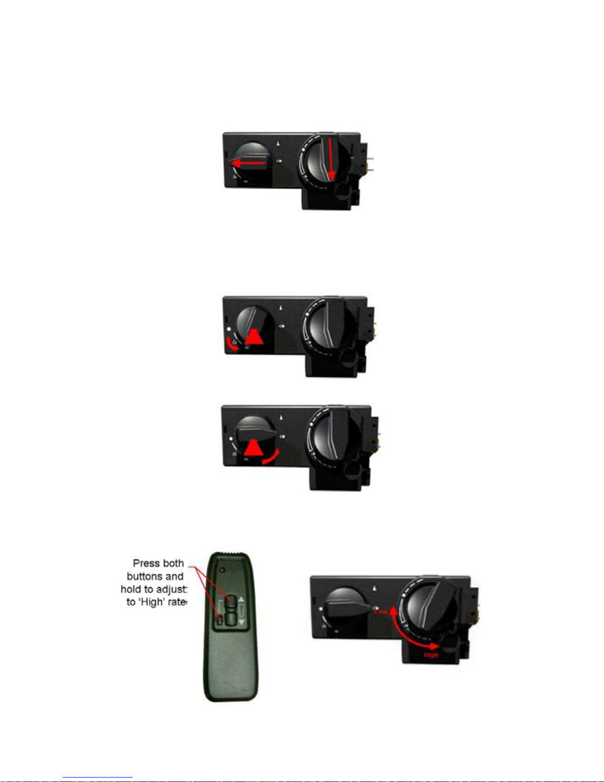
GV60 Lighting
GV60
ON(1)/OFF(0)
Switch
If the GV60 control unit makes a long beep the on/off switch is set on the OFF (0)
position, switch the unit to the ON (1) position.
The GV60 is fully remote controlled. (The GV60 is only available in Infra-red for
safety regulations).
When lighting the fire the remote control must have ‘line of sight’ to sensor.
The Infra-red remote sensor is situated close to the fire unit; the placement may
differ depending on the type of fire basket.

52
To light a fire with a GV60 fitted is different to the GV34/GV36.
The fire unit can be lit using the remote control handset.
To light the fire unit you must press and hold both buttons (star, up arrow) and
the small lower button until a short acoustic signal confirms the start sequence has
begun; release buttons. Continuing signals confirms the ignition is in process. The
fire unit will then light on High rate; if the fire unit is cold it is advised to leave the
burner on high rate for at least 5-10 minutes to warm up the flue before turning
between the ‘High and Low rates.
When the fire has warmed the flame height can be adjusted between ‘High and
Low’ by pressing either both the (up arrow) to increase flame height, or
pressing the (down arrow) to decrease flame height.
The pilot can just remain lit this is done by holding the (down arrow) until the fire
unit turns off the main burner.
To go from the lit pilot to main press the (up arrow).
To turn off the fire unit completely press the off button.

53
Lighting the appliance with a match
GV34/GV36 Control Valves
If the pilot does not ignite as described in ‘Lighting the appliance’, it may be lit
with a match.
Firmly push the left control knob in and rotate counter-clockwise until the
knob is pointing at the pilot position.
Whilst holding the knob in, apply a lighted match to the pilot area circled
below.
Once lit keep the knob pushed in for 5 to 10 seconds and then release, the
pilot should remain alight.
The pilot can then be turned to the ‘Lighting’ position as previously described.

54
GV60 Control Valve
Start the fire with the control handset when the acoustic signal confirms the
start sequence hold the lighted match to the pilot area circled below right.
Once the pilot is lit leave the fire unit finish the sequence.
If the fire is extinguished or goes out in use, allow 3 minutes before
attempting to relight following the lighting sequence stated in ‘Lighting the
appliance’.
If the fire shuts itself off repeatedly do not use the appliance, and have the
flue and fire appliance checked by a suitably qualified person.

55
Changing the batteries (GV34 / GV60)
The batteries will require changing yearly (based on the average
usage) this may differ depending on usage and on the quality of
battery, the battery change is best done on the annual service of the
appliance.
However if the appliance is showing signs of diminishing signal or
during the lighting sequence then the batteries may need changing.
Firstly replace the handset battery before attempting to change the fire
unit battery.
Remote handset battery
1 x 9V block
(Quality alkaline recommended)
Receiver batteries
4 x 1.5V “AA”
(Quality alkaline recommended)
An AC Mains Adapter may be used instead of batteries (only the Mertik
Maxitrol AC Mains Adapter or one approved by Mertik Maxitrol can be
used).
NOTE: During a power outage the AC Mains Adapter must be
unplugged from the receiver to operate in battery mode.
Ensure to follow direction of the batteries (indicated in the compartment).
Check the connections are secure before replacing the box back into the
burner unit.

56
Cleaning
Cleaning should only be carried out when the fire is turned off and cold.
It is necessary to clean the fire if debris or soot deposits have accumulated
on the coals/logs.
A soft brush is advised to clean the coals/logs and burner unit.
NOTE – Do not use a vacuum cleaner for the coals/logs or burner unit.
When placing the coals/logs ensure they are placed as the layout.
(See pages 33 to 39).
Fuel bed components
The ceramic parts are fragile; care must to be taken when handling this
product.
When placing the coals/logs it is important to carefully follow the layouts in
this manual, the layout has been set to give the best performance and flame
picture of the appliance.
Do not use any more ceramic components than those shown, extra parts
supplied are spares for future use.
Ceramic components should last around 2 years in normal use at which time
is recommended that they are replaced.
Replacements can be bought from any Chesney’s stockists. State the model
number (found on the gas fire data plate).
Always ask for genuine Chesney’s parts.
This appliance is manufactured by –
Chesney’s Limited
194 – 200 Battersea Park Road,
London, SW11 4ND
Tel: 020 7627 1410 Fax: 020 7622 1078

57
13. INSTALLER CHECK LIST
FLUE CHECKLIST PASS FAIL
Flue Size
Flow test
Spillage test
GAS CHECKLIST PASS FAIL
Sou
ndness
Standing Pressure
Working Pressure
VENTILATION PASS FAIL
Ventilation requirements for appliance
14. DEALER AND INSTALLER INFORMATION
DEALER AND INSTALLER INFORMATION
Dealer
Installation Company
Contact No. Gas Safe Engineer
Date of Purchase Contact No.
Model No. Gas Safe No.
Serial No. Date of Installation
Gas Type

58
Annual service record
Year 1
Gas Safe Engineer
Contact No.
Gas Safe No.
Date of Service
Annual service record
Year 2
Gas Safe Engineer
Contact No.
Gas Safe No.
Date of Service
Annual service record
Year 3
Gas Safe Engineer
Contact No.
Gas Safe No.
Date of Service
Annual service record
Year 4
Gas Safe Engineer
Contact No.
Gas Safe No.
Date of Service
Annual service record
Year 5
Gas Safe Engineer
Contact No.
Gas Safe No.
Date of Service
Annual service record
Year 6
Gas Safe Engineer
Contact No.
Gas Safe No.
Date of Service
The following information supplied in this manual is correct at the time of publish;
Date of last manual update 24 May 2010. V12.
 Loading...