

Page 1

Preface
1
ADVICE
User’s Manual clarifies the agreement between Chery Automobile Co., Ltd. and the User on the product
quality warranty responsibility and the establishment and termination of after-sales service rights and responsibilities.
Please read this User’s Manual carefully before using our products.
User’s Manual for Chery V5
Sincere congratulations on your own of one Chery V5! Also, with great appreciation on your great favor on our company and our products.
The personnel of Chery authorized service station are trained with good professional trainings, which will sincerely provide you with the top
quality services.
Chery V5 features advanced technology and prominent performances. Your choice of Chery V5 will prove that you have extra-high
requirements on the vehicle performance and design.
Please read this manual carefully, since the information contained in this manual can let you understand how to operate and maintain your
vehicle properly so as to achieve the driving pleasure to the maximum extent.
This user’s manual applies to the Chery V5.
Chery Automobile Co., Ltd.
Page 2

Preface
2
This manual is established based on the
detailed conditions of V5 vehicles
manufactured by Chery Automobile Co.,
Ltd., which only applies to the V5 vehicles
manufactured by Chery Automobile Co.,
Ltd. This manual included the latest
information up to the date when this
manual is printed. Chery Automobile Co.,
Ltd. will be wholly responsible for the
modification and explanation of this
manual and reserved the rights for product
replacement after the print of this manual
without any prior notice. Some pictures in
this manual are illustrations for reference
only. The real article should take
precedence in case of any conflict between
the pictures and the real articles.
This manual is the main evidence for
vehicle quality warranty and first free
maintenance. Please keep this manual in
your vehicle so that it’s available
whenever you need it. When to resell this
vehicle, please hand over this manual and
all the documentation attached with this
vehicle to the new owner so that they are
available whenever the new owner needs
them.
Special Statement
Please make sure to read this manual
before using this product.
Chery Automobile Co., Ltd. (hereafter
referred as “Our Company” or “Chery
Company”) defined the technical
maintenance regulations of the new
vehicle run in and of maintenance at
various stages for the products, of which
including the first 5,000 km maintenance.
Please make sure to abide by above
regulations since above defined
maintenances are vital to the safety
operation and the maintaining of good
running conditions of your vehicle.
Your claim right will be forfeited in case
of the failure of your vehicle or vehicle
parts that arising from the abuse,
negligence, improper use, the maintenance
not in accordance with the specified
mileage/period, or the warranty evidence
not signed or stamped in accordance with
the requirements, or any unauthorized
refit/attachment. Therefore, any direct or
indirect warranty application thereof will
not be accepted by the Chery authorized
service station.
Any problems of Our Company’s products
during use must be overhauled by the
Chery authorized service station. During
the overhaul process, Chery authorized
service station is entitled to decide based
on the conditions to perform the repair by
means of repair or the replacement of
equivalent parts.
If you encountered anything unclear
during the careful reading of this manual,
Chery Company and Chery authorized
service station will give you the detailed
explanation. Also, the precious advices of
vast users are highly welcomed.
Wish you pleasant driving!
Chery Automobile Co., Ltd. reserved all
copyrights of this menu
Page 3

Summary
3
Chapter 1
Summary
Page 4

Summary
4
Before reading this
User’s Manual, you
should understand
following things.
Thanks for your purchase of Chery vehicle.
In order to operate your vehicle properly
and guarantee your rights and benefits,
please spend some time to read this
manual carefully.
This manual provides the important
instructions and hints on the daily driving
and regular maintenance and care, with the
purpose for your familiarity with the
operation of your vehicle. Only the more
understanding to your vehicle can
guarantee the safety and economy of the
vehicle driving as well as enjoy the
pleasure thereof.
Any improper operation may damage your
vehicle as well as may be deprived of your
claim right.
The periodical maintenance to your
vehicle will help maintain the driving
performance and used value of your
vehicle. The Chery authorized service
stations all over the country boasted
numerous repair experts to provide you
with service anytime. The repair personnel
of all authorized service stations, who
passed the professional trainings, can
properly repair your vehicle and vehicle
equipment. The spare parts in Chery
authorized service station are of Chery
genuine spare parts.
Equipment Scope
This manual defined the maximum
possible equipment scope
installed in accordance with the
series V5 model plan till the print date,
namely for all the standard equipment and
optional equipment in series V5 model,
some equipment may be supplied in the
future or may be only available in certain
markets. Therefore, some items in this
manual may not apply to your vehicle.
Alarm Symbols
within This Manual
During the vehicle operation, how to
reduce the damage to the vehicle and the
vehicle equipment and how to avoid the
person injury? In this manual, the answer
for such question is included in the
Page 5

Summary
5
explanation for the alarm symbols with
triangle. Please read carefully and abide
by the contents thereof.
The equipment marked with
asterisk (*) is only used in lot
size on certain model structures, which is
supplied as optional equipment for some
models or is only available in certain
markets.
When this symbol is present on
the vehicle, make sure to read
the related chapters of this manual before
any operations.
We must contribute our
responsibility and liability in the working
of environmental protection. It’s the
important step to achieve such objective
by operating your vehicle properly and
disposing the used cleaning articles and
lubricating materials in accordance with
the laws and regulations. This manual
displayed the information on this aspect by
means of tree symbol.
New Vehicle
Inspection
Before deliver the vehicle to you, the
dealer of Chery Company has already
performed the vehicle inspection in
accordance with the regulations of Chery
Automobile Co., Ltd. The dealer of Chery
Company should fill in the vehicle
delivery date in the "Vehicle Delivery
Inspection Certificate” column of this
manual and seal with the stamp of dealing
agency.
The dealer should verify the entire vehicle
performance and introduce the operation
knowledge of the vehicle against the
“Chery Vehicle Sale & Delivery Card”
that to be dually signed by the salesman
and the user.
Run in of New Vehicle
Due to the manufacture and assembling
deviations, the frication resistances
between the moving components of the
new vehicle at the initial stage of
operation will be much greater than the
ones of normal condition. The run in
effects of the vehicle at the initial stage of
operation will exert great influence on the
use lifetime, working reliability and
economy of the vehicle, therefore, the use
of new vehicle must abide by the run in
Page 6

Summary
6
regulations strictly.
Run in Regulation within 1,000
km
y Full speed driving is absolutely
prohibited.
y Generally, do not drive the vehicle at
the speed above 100 km/h.
y Avoid driving at the top speed at
whichever gear.
Run in Regulation from 1,000 km
to 1,500 km
y Increase to the top speed gradually or
drive at the allowable max engine
speed.
Notice during Run in Period
For the driving of vehicles with engine
tachometer, the allowed short period top
engine speed is 6,000 r/min. During the
manual gearshift, make sure to shift to the
next high gear when the engine tachometer
indicator reached red indication area at the
latest.
Avoid the running of engine at
unnecessary high speed. The
earliest shift to high gear will help save the
fuel, reduce the working noise as well as
diminish the environmental pollution.
The engine speed should not be excessive
low during driving. Shift to proper gear at
reasonable time.
When at cold condition, do not run the
engine at top speed no matter at neutral
gear or any other drive gear.
The new tires don’t have best adhesion at
the beginning of use; therefore, the tires
also need run in. The vehicle speed should
be relative low during first 100 km driving
and the driving should be extremely
careful.
The new brake friction lining also needs
run in, since the brake doesn't have ideal
friction force during first 200 km driving.
During this period the brake effects are a
little poor, therefore the pressure on brake
pedal may be reasonably increased. Such
condition also applies to the each time
when replaced with new friction lining.
When the new vehicle traveled for 800km,
the wheel nuts must be re-tightened to the
specified torque. Please refer to the
chapter “Specification and Parameters” of
this manual for correct torque values. Also,
Page 7

Summary
7
if the wheel has been replaced or the
wheel nuts have been loosened, then the
wheel nuts should be re-tightened in
accordance with the specified torque after
traveled for 800km.
“One-To-One” Service
In order to provide you with better service
and vehicle use, the dealer of Chery
Company will appoint one service counsel
to serve you at the purchase of your
vehicle. In case of any problems during
your vehicle use, you may contact your
service counsel, who will provide you
with best services.
Page 8
Summary
8
Vehicle Register No.:
Vehicle Delivery Inspection Evidence
This is to certify that this vehicle has completed the
vehicle delivery inspection defined by Chery Automobile Co., Ltd.
and its quality met with the technical specification of Chery
Automobile Co., Ltd.
Vehicle Delivery Date: _____________
Dealer Stamp:
Vehicle Owner Name (Unit) Responsible Service Station Name
—————————————————— —————————————————————
—————————————————— —————————————————————
Address
————————————— Responsible————————————
——————————————————————
Tel:————————————————— Te l:——————————————
Page 9
Summary
9
Vehicle Delivery Date
Dealer Stamp
Model:
Body VIN No:
Engine Serial No.:
Transmission Serial No.:
Page 10

Summary
10
Chery Vehicle Sale & Delivery Sheet
Catego
ry
No. Item Whether inspected OK and
clearly explained
1 Engine Yes □ No □
2 Engine oil, brake liquid, steering liquid, coolant, battery liquid, windscreen
cleaning liquid.
Yes □ No □
3 VIN number, engine serial number, nameplate and other identifications Yes □ No □
4 Entire vehicle locks Yes □ No □
5
Entire vehicle lamps, including head lamp, turn lamp, fog lamp, combined lamp,
compartment lamp, brake lamp, backup lamp, tail lamp, reading lamp, door
lamp, and instrument lamp.
Yes □ No □
6 Windscreen glass and body paint Yes □ No □
7 Speedometer, engine tachometer, odometer Yes □ No □
8 Hub cap, spare tire in luggage boot, vehicle attached tools and entire vehicle
operation manual
Yes □ No □
9 Safety belt, seat, cigarette lighter, A/C switch and vent, glove box and sun visor. Yes □ No □
Entire Vehicle Performance
10 Glass lifter, rear view mirror, wiper, washer, horn, sunroof, backup radar, vehicle
telephone, radio (CD player) and antenna.
Yes □ No □
Page 11

Summary
11
1 93# gasoline fuel Yes □ No □
2 Normal operation during run in. Yes □ No □
3 Operation of entire vehicle lamps Yes □ No □
4 Meaning of alarm indicators Yes □ No □
5 Correct maintenance period and mileage Yes □ No □
6 Vehicle maintenance items in winter and summer. Yes □ No □
7 Correct understanding of cooling system/coolant usage. Yes □ No □
8 Correct operation of A/C Yes □ No □
9 Notices for vehicle start Yes □ No □
10 Correct operation of audio equipment Yes □ No □
Oper
ation
Kno
wled
ge
11 Correct operation of sunroof Yes □ No □
Salesman Signature: Date: User Signature: Date:
Page 12

Summary
12
“One-To-One” Counseling Service Card
User Name: Vehicle Purchase Date
Sales Agency: Model:
Vehicle VIN Number:
Following items should be validated by the user:
I. Related items confirmation at vehicle delivery (“√" for Yes as
“×” for No)
□ Basic vehicle operation method has been introduced and the
onsite delivery inspection is certified OK.
□ Quality warranty policy has been introduced.
□ Vehicle driving notices has been introduced.
□ The importance of vehicle periodical maintenance and
maintenance period/mileage has been introduced.
□ The importance of vehicle maintenance/repair at Chery
authorized service station has been noted.
□ User’s Manual has been handed over and the reading is
reminded.
□ The function and operation method of service hotline of Chery
Company has been noted.
II. “One-To-One” counseling service mode introduction (“√” for
Yes as “×” for No)
□ Contact the service counsel instead of anyone else in case of any
problems or needs.
□ The service counsel appointed by the service station is the
exclusive person to communicate and contact with the user.
□ One user is only served by one service counsel: "One-To-One”
□ User may choose other service counsel when dissatisfied with
current service counsel.
III. Major job introduction of service counsel (“√” for Yes as “×”
for No).
□ Repair maintenance service reception
□ Complaint acceptance
□ Periodical maintenance reminding visits
□ Repair/Maintenance counsel explanation
□ Periodical greeting visits
□ Repair/maintenance reservation acceptance
□ Service activity reminding visits
□ Annual authentication reminding/acceptance
□ Important festival greeting
□ Other activities of user’s needs
IV. Establishment of “One-To-One” counseling service
relationship.
Service Counsel Card
User Signature/Date: Service Counsel Signature/Date:
Form One
Page 13

Summary
13
“One-To-One” Counseling Service Card
User Name: Vehicle Purchase Date
Sales Agency: Model:
Vehicle VIN Number:
Following items should be validated by the user:
I. Related items confirmation at vehicle delivery (“√" for Yes as
“×” for No)
□ Basic vehicle operation method has been introduced and the
onsite delivery inspection is certified OK.
□ Quality warranty policy has been introduced.
□ Vehicle driving notices has been introduced.
□ The importance of vehicle periodical maintenance and
maintenance period/mileage has been introduced.
□ The importance of vehicle maintenance/repair at Chery
authorized service station has been noted.
□ User’s Manual has been handed over and the reading is
reminded.
□ The function and operation method of service hotline of Chery
Company has been noted.
II. “One-To-One” counseling service mode introduction (“√” for
Yes as “×” for No)
□ Contact the service counsel instead of anyone else in case of any
problems or needs.
□ The service counsel appointed by the service station is the
exclusive person to communicate and contact with the user.
□ One user is only served by one service counsel: "One-To-One”
□ User may choose other service counsel when dissatisfied with
current service counsel.
III. Major job introduction of service counsel (“√” for Yes as “×”
for No).
□ Repair maintenance service reception
□ Complaint acceptance
□ Periodical maintenance reminding visits
□ Repair/Maintenance counsel explanation
□ Periodical greeting visits
□ Repair/maintenance reservation acceptance
□ Service activity reminding visits
□ Annual authentication reminding/acceptance
□ Important festival greeting
□ Other activities of user’s needs
IV. Establishment of “One-To-One” counseling service
relationship.
Service Counsel Card
User Signature/Date: Service Counsel Signature/Date:
Form Two
Page 14

Page 15
Interior Device Operation and Adjustment
15
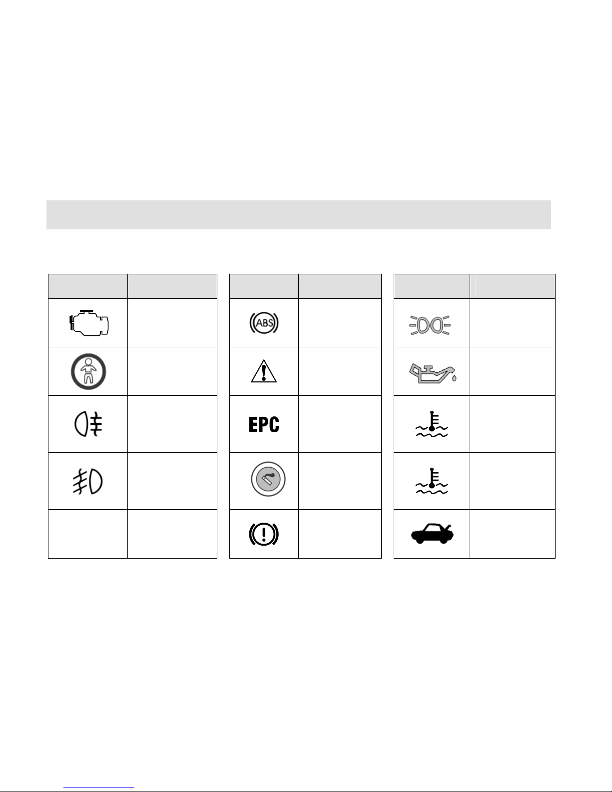
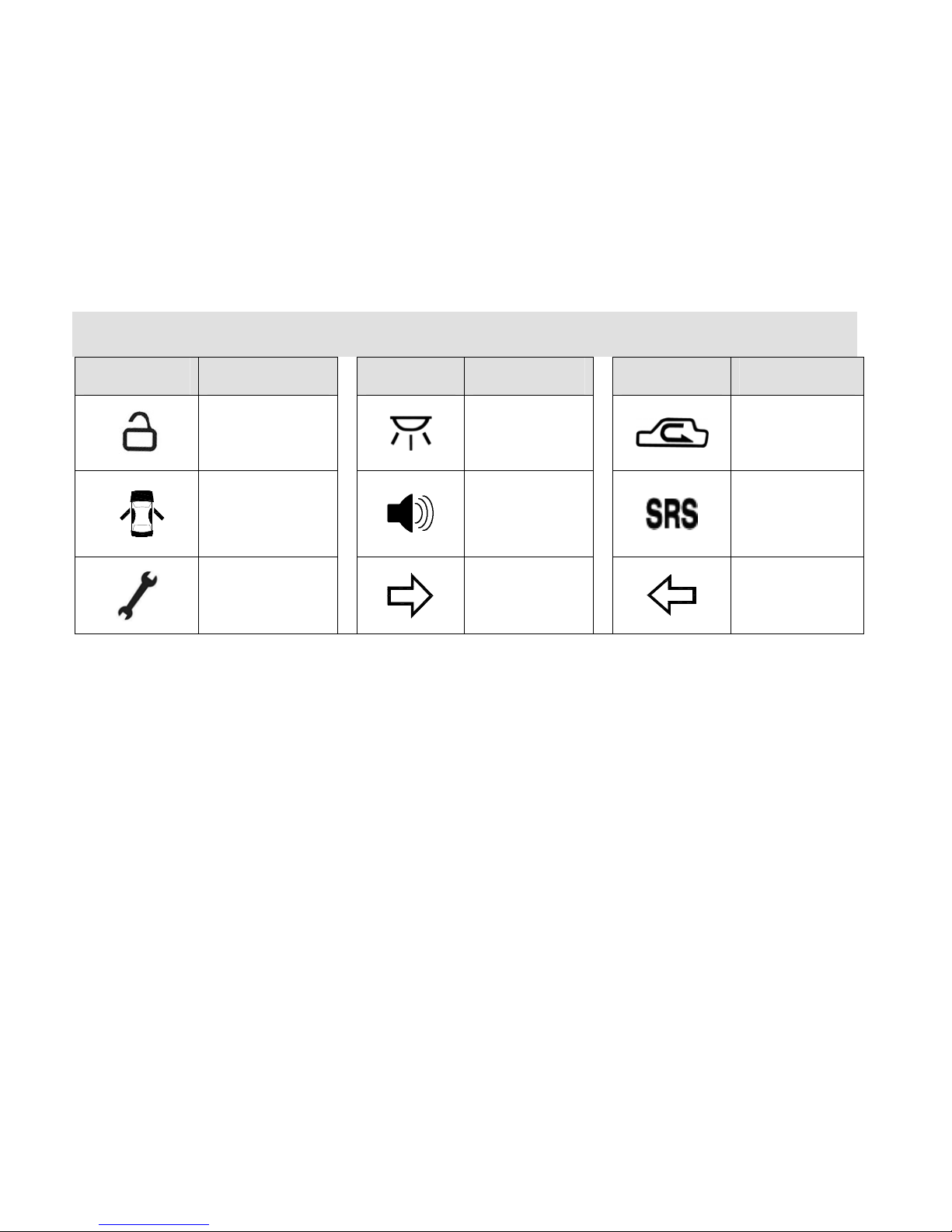
Common Vehicle Symbol Instruction
Symbol Definition Symbol Definition Symbol Definition
Engine
self-examination
trouble light
Anti-lock brake
system
Position lamp
Glass lifter switch
prohibited
Safety warning
Engine oil pressure
alarm lamp
Rear fog light
Throttle trouble
indicator
Coolant
temperature
overheating alarm
(red indicator)
Front fog light
Cigarette lighter
Coolant
temperature
normal indicator
(green indicator)
A/C
A/C system
Brake system
trouble alarm
lamp
Luggage boot door
opened
Page 16
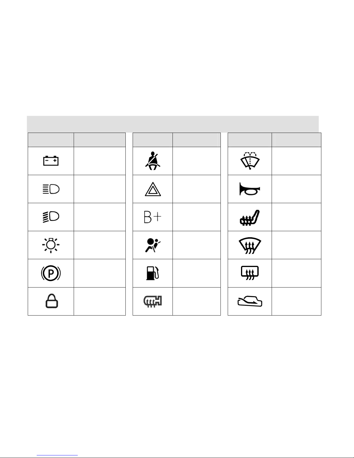
Interior Device Operation and Adjustment
16
Symbol Definition Symbol Definition Symbol Definition
Battery
Fasten the safety
belt
Windscreen
cleaning
High beam lamp
Danger flash
alarm lamp
Horn
Low beam lamp
Power + pole
Seat heating
Head lamp switch
Air bag trouble
indicator
Windscreen
defrosting
Parking brake
indicator
Low fuel level
alarm indicator
Rear windscreen
heating indicator
Lock indicator
External rear view
mirror heating
External air
circulation
Page 17
Interior Device Operation and Adjustment
17
Symbol Definition Symbol Definition Symbol Definition
Unlock indicator
Interior lamp
switch indicator
Internal air
circulation
Door and luggage
boot cover not
closed alarm lamp
Sound alarm
Air bag
identification
Ve h i cl e
maintenance
indicator
Right turn
indicator
Left turn indicator
Page 18
Interior Device Operation and Adjustment
18
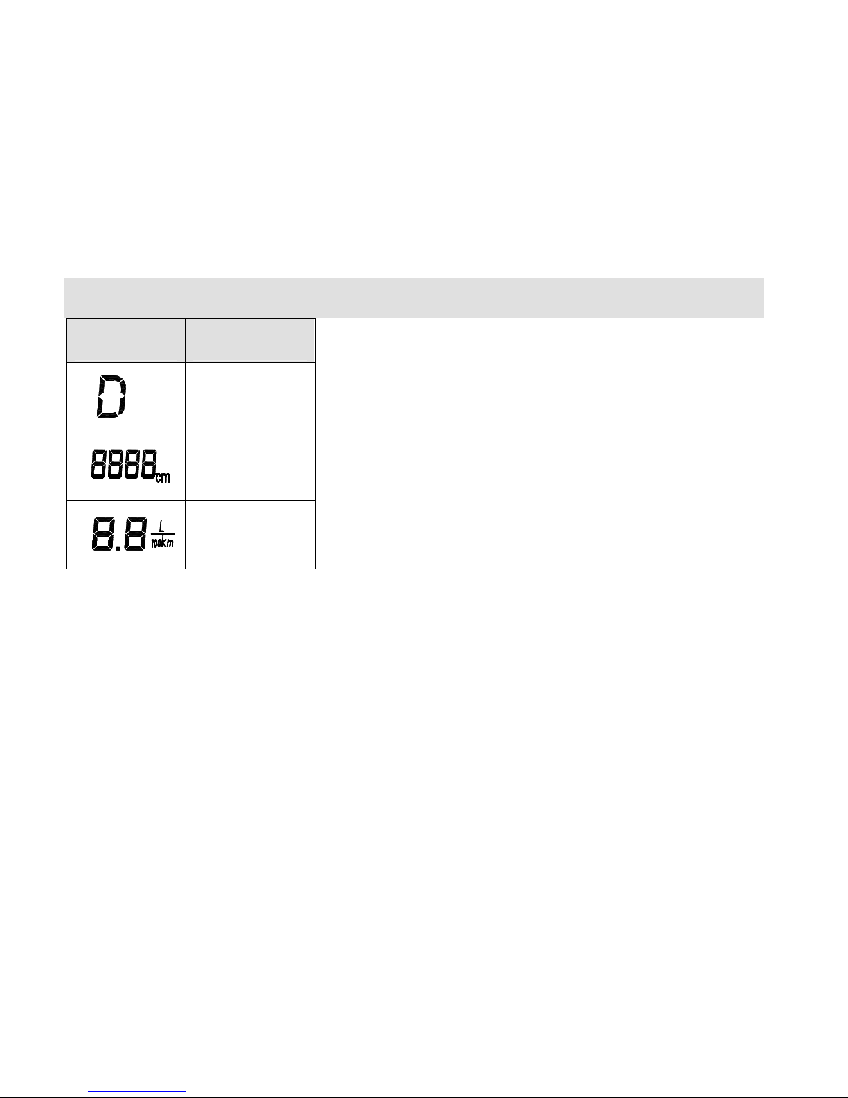
Symbol Definition
Transmission gear
position indicator
Backup radar
distance display
Fuel consumption
display
Page 19

Interior Device Operation and Adjustment
19
Chapter 2 Interior Device Operation and Adjustment
Page 20
Interior Device Operation and Adjustment
20
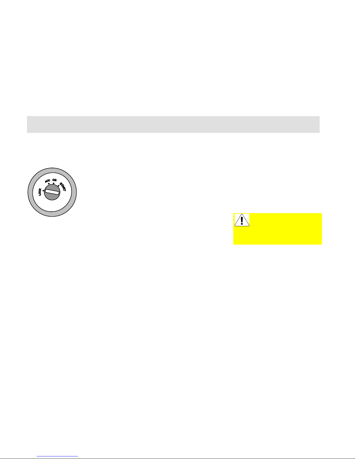
Steering Wheel/
Ignition Switch
The combined steering wheel
lock/ignition switch has following key
positions:
LOCK - Ignition switch is turned off
as the steering wheel is locked.
When the key is pulled out from the
ignition switch, the steering wheel lock
will actuate to lock the steering wheel.
In order to lock the steering wheel,
rotate the steering wheel once after the
withdrawal of the key, till the
engagement sound as the steering
wheel is locked.
ACC – Unlock of steering system.
When the circuits of the electrical
accessories are turned on, the small
electrical appliances such as interior
lamp can be operated, however the
ignition switch and the main electrical
circuits are all turned off.
If it fails or has difficulty to rotate the
key from the LOCK position to such
position, the lock mechanism of the
steering wheel can be released by rotate
the steering wheel around slightly.
The ignition switch key should not be
left at such position overlong so as to
avoid the depletion of the battery
power.
ON – All electrical circuits can operate
once the ignition circuit is turned on.
The alarm lamp and the indicator will
light. This is the normal position of key
during driving as well as the position
must be selected during vehicle towing.
ST ART – Turn on the start motor and
start the engine.
When the key is at such position, the
front headlamp and the electrical
devices with higher power
consumption will be turned off.
The ignition switch is equipped with
repeated start proof device internally.
Once the engine is running, such
device can prevent the mis-start of the
starter so as to avoid the damage to the
starter and the engine flywheel.
If the start fails, then it’s must to rotate
the ignition key to LOCK position
before rotate to this position for restart.
After start, the key will bounce back to
ON position when the key is released
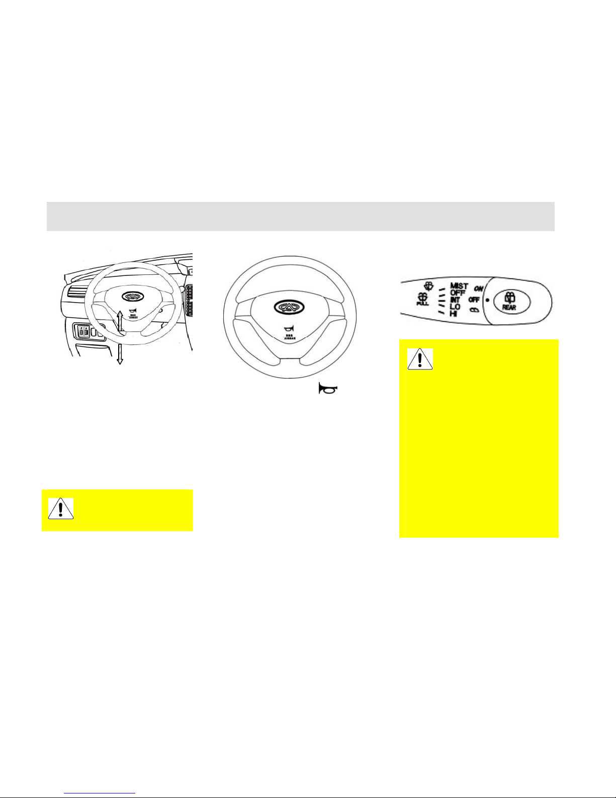
Adjustment of Steering
Wheel
The key must be released
once the engine is started.
Do not hold at the START
position for much longer.
Page 21
Interior Device Operation and Adjustment
21
In order to drive the vehicle safely and
comfort, sometimes the height of the
steering wheel should be adjusted. At
such time, pull downward the
adjustment handle under the steering
pillar cover to release the handle and
then the steering wheel can slide
up-and-down. After adjusted to
position, pull upward the adjustment
handle to lock position and lock the
position of steering wheel.
Horn
Press the button with mark on
the steering wheel to operate the horn.
The horn is still operational under the
status that the ignition switch is turned
off.
Windscreen Wiper and
Washing System
In cold season, make sure to
check if the wiper blade is
frozen onto the windscreen
before using the wiper. If frozen onto
the windscreen, then it’s the must to
defreeze the blade before use;
otherwise it will cause the damage of
the wiper motor.
If the windscreen has obstacles such
as snow accumulation, the operation
of wiper will also cause the damage
of the wiper motor.
Please remove the obstacles before
the operation of the wiper.
Do not operate the wiper on the dry
windscreen; otherwise the windscreen
glass will be scratched and it will
cause permanent damage to the wiper.
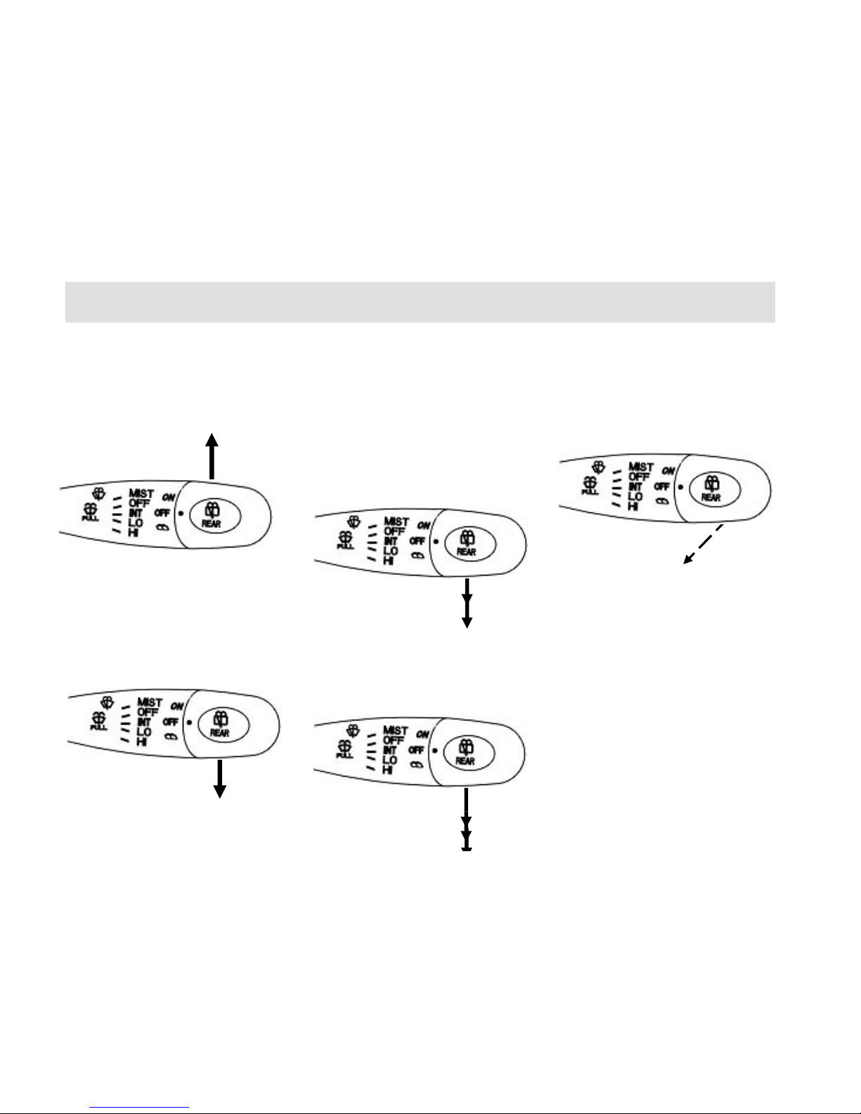
The wiper can be actuated only when
Do not adjust the steering wheel
during driving.
Page 22
Interior Device Operation and Adjustment
22
the ignition switch is turned on. The
front windscreen switch totally has 5
positions and will stop at OFF position
when unused.
Single Wiping
Pull the control lever upward to MIST
gear and the control lever will return to
OFF position automatically upon
release. The wiper will operate only
once.
Intermitted Wiping
Move the control lever downward from
OFF position to INT gear after passing
through one position.
The wiper controller will operate
automatically once for every certain
interval.
Normal Wiping
Move the control lever downward from
OFF position to LO gear after passing
through two positions.
High Speed Wiping
Move the control lever downward from
OFF position to HI gear after passing
through three positions.
Water Spray Switch
When pull the switch handle toward the
steering wheel and hold, the cleaning
liquid will be sprayed out from the
water spray opening in front of the
windscreen and the wiper will operate
accordingly. The water spray will stop
spray upon release of the switch and
the wiper will continue the operation
for several cycles.
Page 23
Interior Device Operation and Adjustment
23
The operation period of
water spray should not
exceed 10 s for each time.
This operation is absolutely
prohibited when the reservoir has no
cleaning liquid; otherwise it may
cause the damage of the water spray
motor.
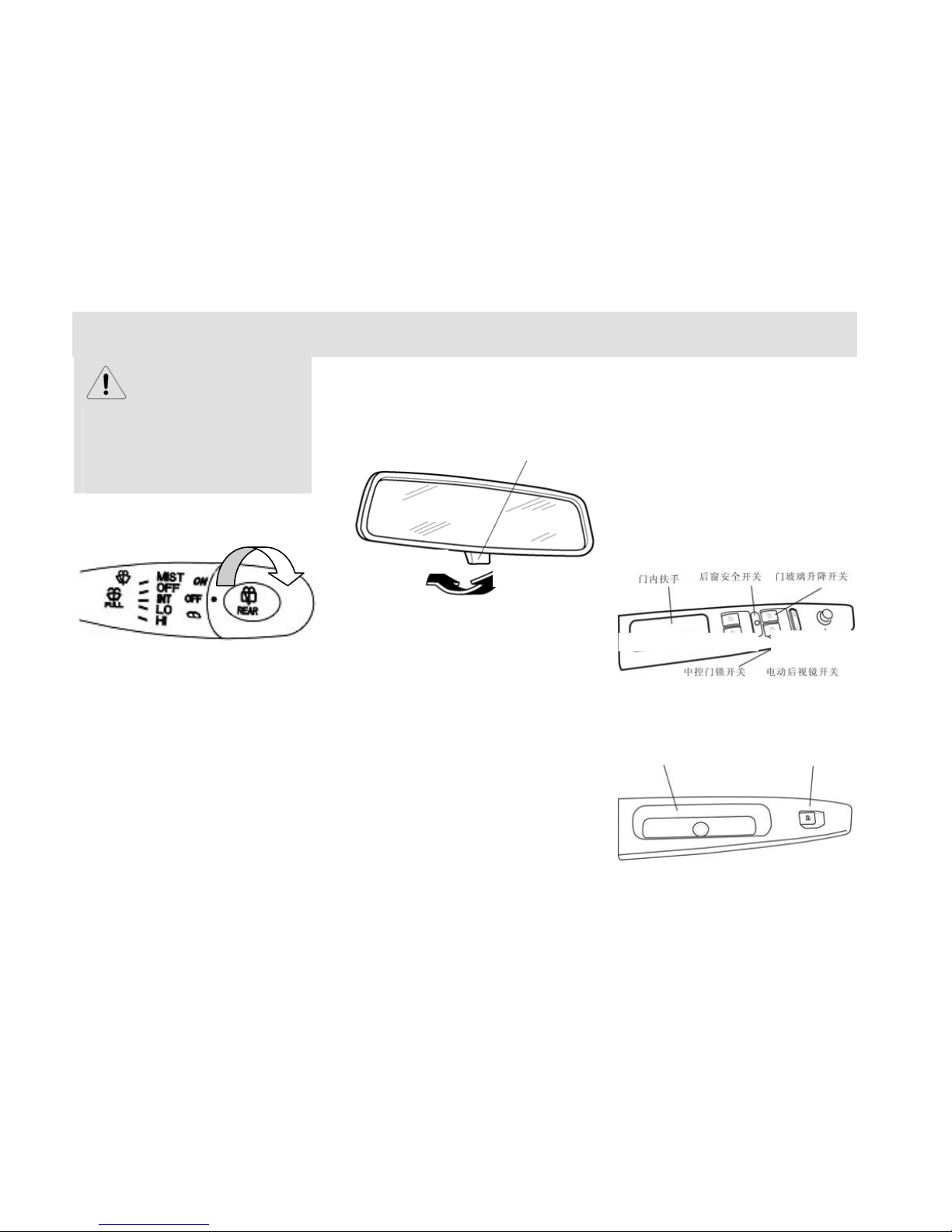
Rear Windscreen Wiper
Switch
The wiper will start working when
rotate the switch head to the ON
position and will stop working when
rotate to the OFF position. When rotate
the switch head downward from the
OFF position and hold, the rear
windscreen water spray will start
working and the rear windscreen wiper
will act accordingly. The switch will
return to OFF position automatically
upon release of the switch.
Interior Review View
Mirror
When to reduce the dazzling during
driving at night, pull the adjustment
lever backward to adjust the angle of
the rear view mirror.
Sun Visor
The sun visor can be released from the
fixing clip and rotate towards the side
window.
The back of the sun visor can store the
things such as driving license and
bridge & road passage fee invoice.
Door Control Switch
Driver side switch
Rear row passenger switch
Dazzling proof fork
Daytime driving
Nighttime driving
Interior armrest
Rear window safety
switch
Rear window safety
switch
Central lock switch
Electrical rear view mirror
switch
Interior armrest
Window regulator
Page 24
Interior Device Operation and Adjustment
24
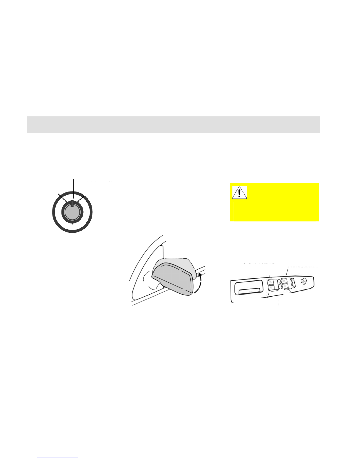
Electrical External Rear
View Mirror
The electrical rear view mirror can be
adjusted by the adjustment switch on
the driver side door. The adjustment
switch will be operational only when
the ignition switch is turned on.
Rotate the adjustment switch
counter-clockwise to position to adjust
the external rear view mirror at the left
side; rotate clockwise to position to
adjust the external rear view mirror at
the right side.
After rotate the adjustment switch
leftward or rightward to position, pull
the switch toward front, rear, left, or
right direction to adjust the up, down,
left or right position of the mirror. At
the finish of mirror position adjustment,
rotate the switch back to the middle
position.
If necessary, such in the narrow space,
it may fold the external rear view
mirror inward manually. When to
restore original position, fold the rear
view mirror outward till clip into the
correct position.
The images in the convex
rear view mirror seem
smaller and further than the
rear things. Notice not to
overestimate the real distance of the
things.
Electrical Window
Left Front Door
Middle Position
Left rear view mirro
r
adjustment position
Right rear view
mirror adjustmen
t
Left rear door window
regulator switch
Left front door window
regulator switch
Right rear door window
regulator switch
Right front door window
regulator switch
Page 25
Interior Device Operation and Adjustment
25
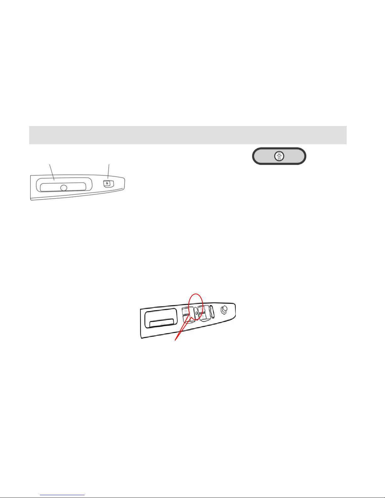
Rear Door
The electrical window will be
operational only when the ignition
switch is turned on.
Each window can be operated by the
control switch on the corresponding
door trim panel.
Push down or lift up the switch to open
or close the window. The window glass
will stop at current position when the
switch is released during the ascending
or descending process of the window
glass.
The glass regulator switch has time lag
function, namely the glass regulator
switch is still operational within 60 s
after the key is pulled out.
Each window glass has one-touch
function during the descending of the
window glass, namely the glass will
descend to the end if the descending
switch is pressed for 1 s before release.
Besides the control switch for the
driver side window, the driver side door
trim panel still has the control switches
for other three windows.
Rear Window Safety
Switch
The driver side door trim panel also has
one safety switch button. When this
button is pressed, the function of the
electrical windows for right front door
and two rear doors will be disabled. At
that time, the open/close of the
windows is only controlled by the
switches at the driver side. It's
recommended to conduct such
operation when there has child sitting
at the rear row seat.
Notice:
Cautions should be taken when closing
the window! The observation should be
noticed to avoid the occurrence of the
squeezing accident.
Interior armrest
Door window regulato
r
switch
Page 26
Interior Device Operation and Adjustment
26
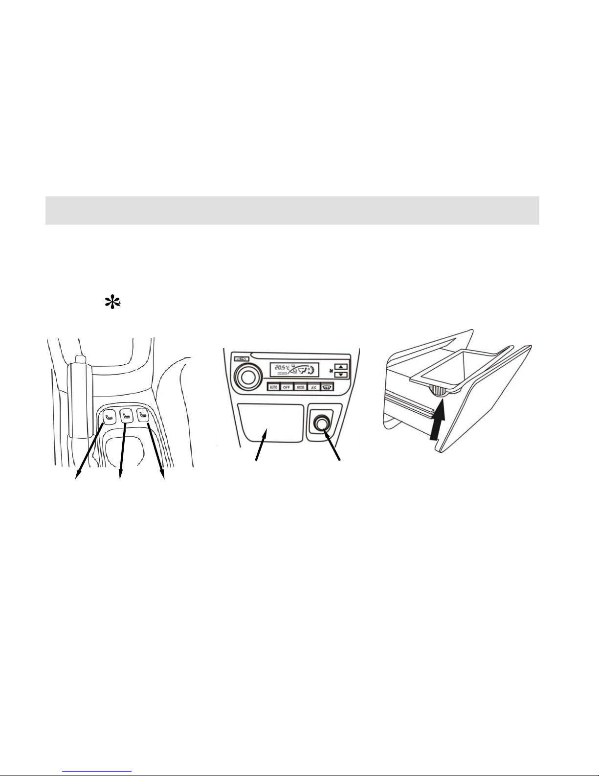
Driver Seat Heating
Switch ( )
The heater of each seat will work when
the corresponding switch is pressed.
The further press of the switch will
stop the heating.
Front Row Ashtray/
Cigarette Lighter
Located in front of the gearshift lever.
The ashtray will eject out automatically
by pulling the cover plate forward once
before releasing. When to empty the
ashtray, remove the internal ashtray
case to empty.
The cigarette lighter is located at the
right side of the ashtray. When to use
the cigarette lighter, push it in and wait
it to eject out. The cigarette lighter is
still operational even when the ignition
Driver
side
heater
switch
Seconda
r
y driver
side
heater
Rear row
seat
heater
switch
Front row
ashtray
Cigarette
lighte
r
Page 27
Interior Device Operation and Adjustment
27
switch is turned off.
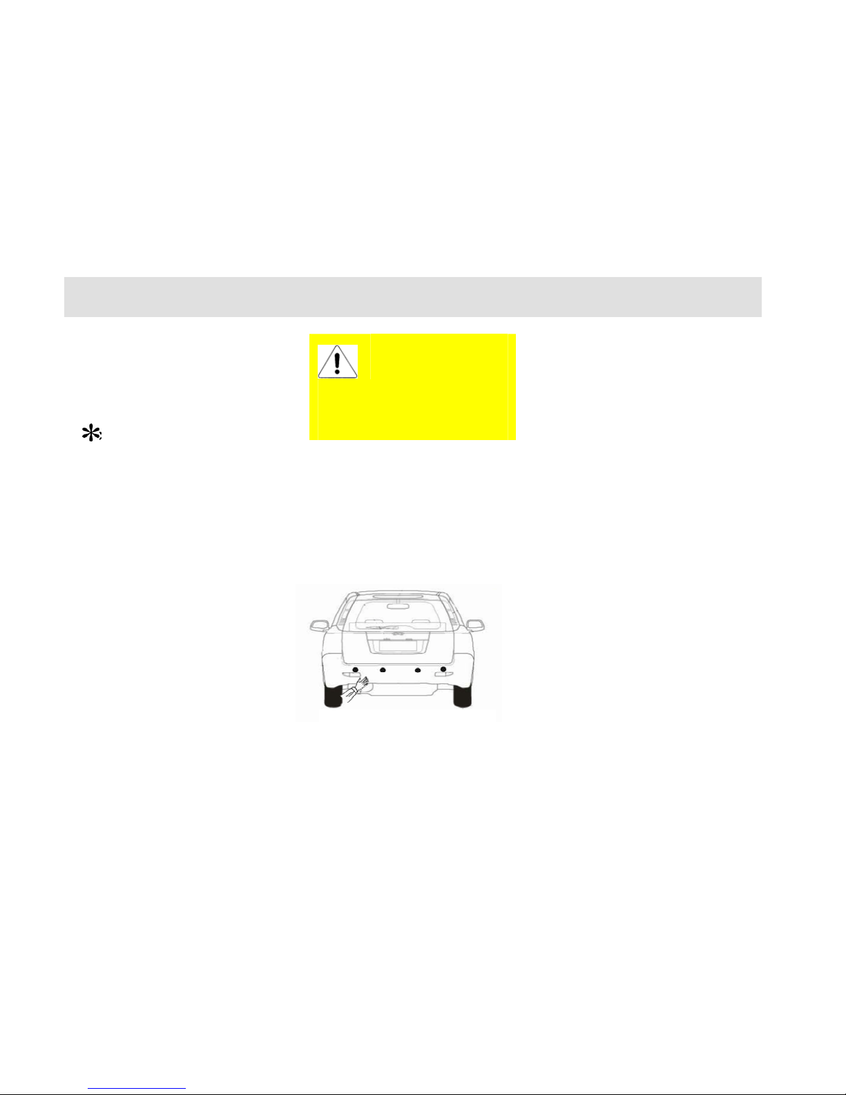
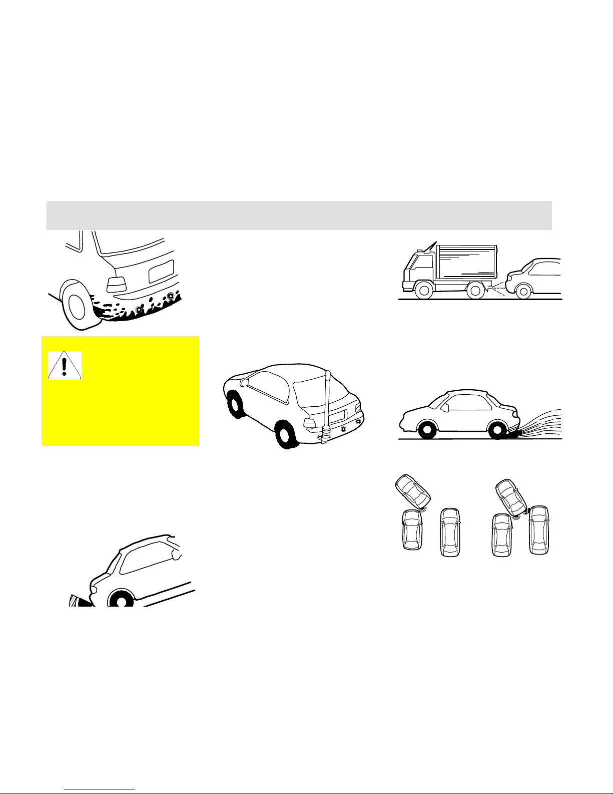
Backup Radar System
( )
The backup radar assistant system is
the device to inform the driver when
the rear of the vehicle closes to the
obstacles by means of the alarm sound
(buzzer) and distance display (display
screen). (The following illustrations
may differ from the real articles and the
real articles should take precedence).
Before use, rotate the ignition key to
ON position and pull the gearshift lever
to the position of reverse gear. When
approach to the obstacle, the central
radar probe will have slow intermitted
sound from approximate 90 cm and the
left/right rear corner radar probe will
have rapid intermitted sound from
approximate 60 cm.(It may place the
hand at the probe to confirm the
detection scope)
Make sure that the slow
intermitted sound will change to the
rapid intermitted sound when the hand
reaches the central radar probe
approximate 60 cm.
Make sure it will change to
continual sound when the hand reaches
the radar probe approximate 35 cm.
The further approach will have no
sound or change to intermitted sound.
The rear of the vehicle is equipped
with 4 probes. The detection distance
of central parking radar probe is 0~150
cm with the alarm sound comprised of
4 phases; The detection distance of the
left/right backup radar probe is 0~90
cm with the alarm sound comprised of
3 phases. The detailed explanation is as
follows: (C: Central radar probe; L/R:
Left/right radar probe; the distance
Do not leave the cigarette
lighter at the inserted
status for long period so
as to avoid the danger. Please
remove the cigarette lighter when
leaving the child alone in the
vehicle.
Confirm detection scope
Conform the detection scope
Page 28
Interior Device Operation and Adjustment
28
display will take 5 cm as one jump
grade. The display will be 120 cm if the
real distance is 123 cm.
The parking radar probe will
detect the nearest object. It should
be noted that it may not detect the
bumper of the vehicles with higher
body height.
Based on the change of the
specification, the contents of this
manual may differ from the real
vehicle. Please accept our apology.
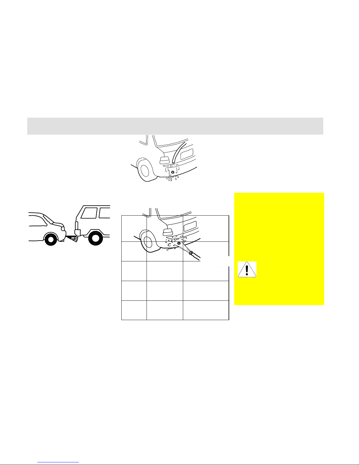
Wipe with cloth or wash with
water (low pressure) the snow or mud
that stuck on the surface of backup
radar probe.
The high
pressure water
flow such as
squirt gun or the
great foreign
force may
result the
malfunctions.
Do not apply squeezing or impact on
the surface of the radar probe.
If the radar doesn’t alarm even closing
to the obstacles, please check
following items:
Backup
Radar
Probe
Position
Obstacle
Distance
Alarm Sound
C Approximate
within 150
cm
Slow intermitted
sound of “dee…
dee… dee…”
C/L/R Approximate
within 90 cm
Slow intermitted
sound of “dee…
dee… dee…”
C/L/R Approximate
within 60 cm
Rapid intermitted
sound of “dee
dee dee…”
C/L/R Approximate
within 35 cm
Continuous
sound of
“Dee............."
High pressure
water flow
Page 29
Interior Device Operation and Adjustment
29
● Whether the surface of radar
probe is stuck with snow or mud.
● Whether the surface of the radar
probe is frozen.
● Whether parked the vehicle in hot
or cold weather for a long period.
If all above items are excluded, please
deliver your vehicle to Chery
authorized service station for checking
and repair.
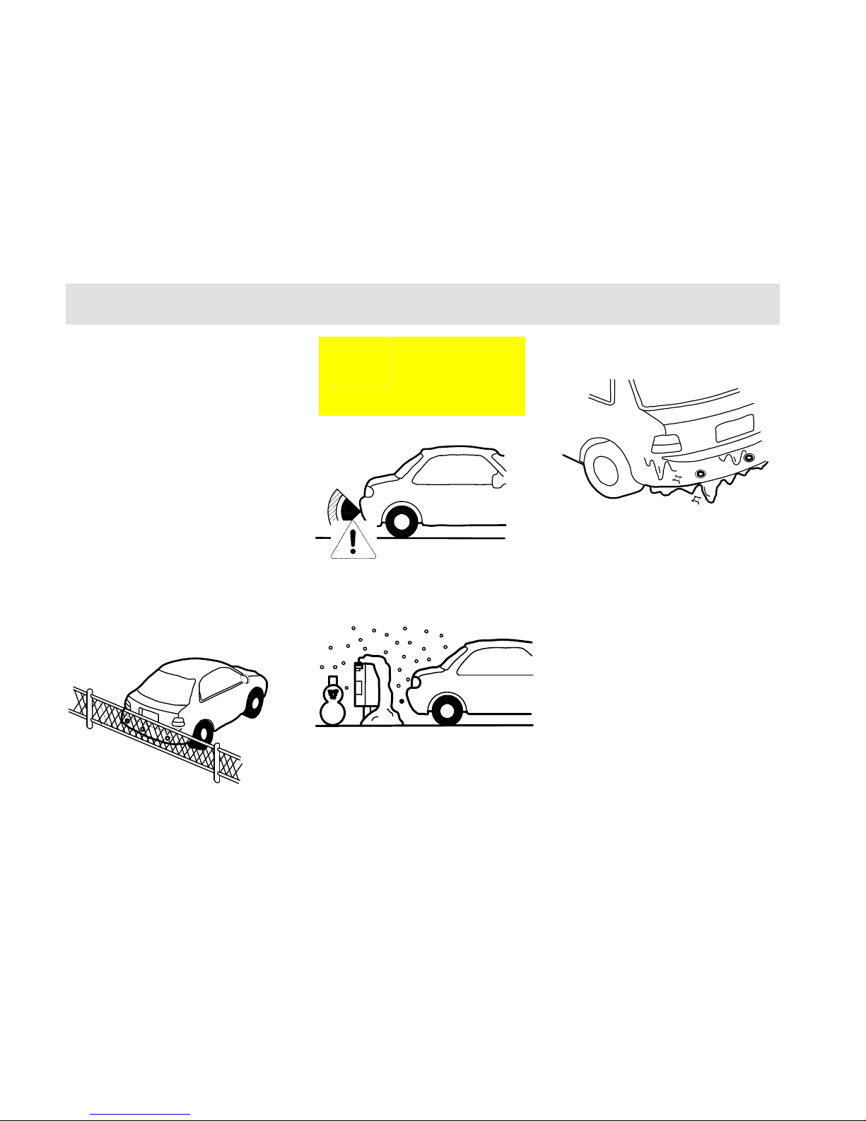
Please notice the following conditions, of
which the radar probe may not alarm even
closing to the obstacles.
● The thin objects such as steel wire,
rope, wire net.
● The short objects such as rock.
● The soft objects that easily absorb
the ultrasonic wave such as snow,
cotton or sponge.
● When the splashed water is frozen
on the surface of the radar probe.
● When the radar probe is stuck
with snow or mud that covered the
backup radar probe.
The radar probe may
not function below -20
℃ or above 50℃.
Page 30
Interior Device Operation and Adjustment
30
Please notice the following conditions,
which may result the wrong detection
alarm.
● The thin objects such as steel wire,
rope, wire net.
● When using the equipped high
output wireless or antenna.
● When encountered the horn of
other vehicles, the engine sound of the
motorcycle, and the approach of the
objects with the issuance of pneumatic
braking sound.
● When driving in the jelly rain or
snow.
It will not alarm the obstacles out of
the detection scope.
When having several
obstacles, the backup
radar probe will only alarm the
obstacle with nearest distance.
During the vehicle movement,
please notice that the backup radar
probe at another side may
approach to other obstacles.
Page 31

Interior Device Operation and Adjustment
31
● For the objects that hardly reflect
the ultrasonic (as shown in figure
below), it may not alarm
depending on the shape of the
obstacle.
基石
自行车胎
瓦楞纸
柱
细的树
角材
Front Passenger Air
Bag (PAB) Switch
It’s not allowed to take child at the
front row passenger seat since the
blown-out of the air bag will cause
certain injury to the child. Therefore,
it’s recommended not to place the child
at the front row passenger seat when
taking the vehicle. Please operate in
accordance with the following items
when it’s must to place the child at the
front row passenger seat.
Open the glove box before driving,
plug one half of the key into the hole of
the front row passenger air bag (PAB)
and rotate clockwise to ON position,
which indicates that the passenger side
air bag circuit is connected and will
blow when certain conditions are met;
when rotate counter-clockwise to OFF
position, it indicates that the passenger
side air bag is turned off and will not
blow.
In order to remind the driver of the
ON/OFF status of the driver/passenger
air bag switch before driving, the
instrument is equipped with PAB
working indicator lamp, which will
light to remind the driver of noticing
the position of the PAB switch when
the ignition switch is turned on.
Corrugated
p
aper
Pillar
Thin tree
Bicycle tire
Base stone
Corner
material
Page 32

Page 33

Driving
33
Chapter 3 Driving
Page 34

Driving
34
Driving
Start
Preparation before Start
The engine start is controlled by the
engine electrical control system.
Do not step the accelerator before start
and during start when start the
electrical injection engine. The
accelerator should be used only when
having difficult start. Please refer to the
section “Engine Start” for the details of
vehicle start.
The long period high speed
idling running of the engine
will result the overheating of
the engine and the exhaust system,
which may result the danger of fire or
other damages. Therefore, do not park,
idling run or driving on the ground
covered with dry grass and other dry
coverings. The exhaust system will
increase the temperature of the engine
compartment and the exhaust pipe that
may cause fire.
Do not start the vehicle in the
closed garage or other closed
locations since the vehicle
exhaust gas is poisonous. Make sure to
open the garage gate before the engine
start. Refer to the section “Caution of
Vehicle Exhaust Fume” for details.
Safety Notice
The idle speed of the engine is
controlled by the electrical control
system. The idle speed at engine start is
relevant high to help increase the
engine temperature. The idle speed
should reduce automatically when the
engine temperature is increased. Please
deliver your vehicle to the Chery
authorized service station for overhaul
if the idle speed can’t reduce
automatically. Do not run the engine at
the speed higher than specified idle
speed for more than 10 min.
Before Vehicle Start
1. Make sure all passengers are
fastened with safety belt. Please
refer to the chapter "Seat and
Safety Protection Device” for the
details of safety belt and its
correct operation method.
2. Make sure the front head lamp
and other electrical fittings are
turned off.
3. Make sure to lift up the
handbrake.
4. Make sure that the gear selector
lever is at neutral gear or parking
gear.
5. Switch the ignition switch to
(ON), but not to (START).
If the rotation of the key needs great
effort, it may rotate the steering around,
till the key can rotate freely. The
occurrence of such condition may have
following causes:
y Deflection of front wheel.
y The front wheel touched with the
road curb.
Page 35

Driving
35
y The steering wheel is rotated
during get-on and get-off
(self-lock of the steering wheel).
6. At the same time when the
ignition key is turned on, make
sure that the dashboard alarm
lamp lights shortly. If negative,
then it needs to deliver your
vehicle to the Chery authorized
service station for overhaul.
If the driver safety belt is fastened
before turn on the ignition key, then the
safety belt alarm lamp won’t light.
Engine Start
1. Rotate the ignition switch to the
START position but not step
down the accelerator (if equipped
with automatic transmission,
make sure to confirm that the
gearshift lever is at P or N gear
before start), release the key after
the engine start, and the key will
return to ON position.
2. IF the temperature is higher than
-12° C, then the engine should
not be started within 5 s during
the first start. Instead, it should
rotate the key to the OFF position
and wait for 10 s before retry.
3. IF the temperature is lower than
-12° C, then the engine should
not be started within 15 s during
the first start. Instead, it should
rotate the key to the OFF position
and wait for 10 s before retry. If
the two consecutive starts all fails,
then step the accelerator to the
end and hold before rotate the
key to the START position. After
the engine start, release the key
and release the accelerator pedal
slowly following the increasing
of the engine speed.
4. After the engine start, run at idle
speed for several seconds, step
down the clutch, shift to the drive
gear, release the handbrake and
prepare the driving.
5. The normal environment
temperature condition of the
engine start is -25 ~40 (it ℃℃
may present other abnormal
conditions when the environment
temperate is out of such scope).
Caution of Vehicle
Exhaust Fume
In despite of without color or smell, the
vehicle exhaust fume contains the
carbon monoxide, of which the danger
must be cautioned. The certain contents
in the engine exhaust gas and the
certain chemicals contained or emitted
by certain vehicle components may
result the carcinogen, the defect of the
new born or other damage of the
genital system.
If smelled the fume
peculiar smell within the
vehicle, please deliver your
vehicle to the Chery
authorized service station for
overhaul immediately. Do not
continue to drive. The exhaust fume is
one poisonous substance that may
endanger the life.
The exhaust system and the vehicle
ventilation system should be checked
under following conditions:
y When the vehicle is lifted for
overhaul.
Page 36

Driving
36
y When the sound of exhaust
system is changed.
y When the vehicle is damage due
to the collision.
Ventilation Notice
When the vehicle is parked in the open
field for long period idle or when the
persons rest in the vehicle, the window
should be opened for at lease 2.5 cm.
Or open the A/C system ventilation
function to let the fresh air into the
vehicle.
Clean the snow, leaf fall or
other foreign articles that
stocked in the air inlet so
as to improve the vehicle ventilation
capability.
Engine Control System
Adaptive Function
If the battery cable is once removed
from the battery before refit, then the
vehicle may present some abnormal
evidences during the initial period of
the driving. This is the engine control
system is re-learn to adapt to the engine,
which belongs to normal condition.
Engine Speed Limit
The engine speed is limited by the
electrical control unit (ECU) so as to
protect the engine.
Engine Turn-Off
Release the accelerator pedal. Wait the
engine to lower to idle speed and then
turn off the ignition switch.
Please do not step down the
accelerator pedal before
turn off the engine.
After long period high speed driving,
do not turn off the engine immediately
after parking. Run the engine at the
speed higher than idle speed for two
通风口
Page 37

Driving
37
more minutes so as to lower the engine
temperature gradually.
Turn off the ignition switch, the
temperature will still be
very high after the turn-off
of the engine and the
radiator electrical cooling fan will still
keep running. Even the cooling fan
stops running, it may run suddenly
again due to excessive high
temperature. Therefore, cautions
should be taken when working near
the engine so as to avoid the scalding.
Brake
Dual-Circuit Brake System
Your vehicle is equipped with
dual-corner dual-circuit brake system.
The remaining circuit will still keep
effective operation even if one circuit
has fault.
In case of the failure of one
brake circuit, it will needs
more force to step down
the brake pedal and the stop distance
will be lengthened. In case of the
occurrence of such condition, please
deliver your vehicle to the Chery
authorized service station for
overhaul before you continue your
journey.
Brake Liquid
If the brake system alarm lamp doesn’t
turn off upon the release of the
handbrake, it indicates that the brake
system has trouble or the brake liquid
level is too low.
The brake liquid level should be
checked periodically in accordance
with the requirements.
Please refill with brake
liquid immediately to
maintain the liquid level at
MAX marking and deliver your
vehicle to the Chery authorized
service station for the checking of the
brake system.
Operation Instruction of
Brake System
It’s quite normal if the brake system
issues noise occasionally. The long
period grinding or screaming noise
between the metal and the metal may
indicate that the brake disc was
severely worn out and should be
replaced. At that time, please deliver
your vehicle to the Chery authorized
service station for overhaul.
If there have consecutive shake or
shock transmitted to the steering wheel
during braking, please deliver your
vehicle to Chery authorized service
station for overhaul immediately.
The new brake lining can achieve best
brake effects only after run in. The
brake effects may be slightly lowered
within the initial 200 km. Under such
condition, the brake effects can be
compensated by enhancing the proper
force on the pedal. This essential point
also applies to the new brake lining
Page 38

Driving
38
All pedals should be
stepped down to the
end and should fully
return with free
after replacement.
The worn-out status of the brake lining
depends on the working condition and
driving method to large extent. For the
vehicles mainly for city transportation,
the working condition of the brake
lining is relatively poor due to the
frequent start and stop. Therefore,
make sure to deliver your vehicle to the
Chery authorized service station for the
checking of brake lining thickness or
the replacement of brake lining in
accordance with the maintenance
mileage specified in the Maintenance.
For downward slope driving, it should
shift to low gear at proper time so as to
sufficiently take advantage of the brake
effects of the engine and reduce the
load of brake system. At that moment,
the brake pedal should be stepped
down all the time even the braking is
required.
The moisture brake disc will reduce the
brake efficiency. After paddling, heavy
rain or car wash, it should step down
the brake pedal slightly to generate
friction heat between the brake disc and
the brake lining so as to evaporate the
water and resume brake effects.
If the vehicle is equipped
with front boiler, it should
ensure the free airflow to the front
brake; otherwise the brake system may
overheats due to poor heat radiation to
reduce the brake effects.
Brake Booster:
If the brake booster can’t function
because the vehicle is trailed or due to
its own fault, then it needs to enhance
the stepping force to compensate the
boosting effects of the booster.
Therefore, it’s preferable not to place
the foot cushion or other covering on
the floor around the pedal. If really
needed, then make sure that the
placement of foot cushion won’t
obstruct the pedal movement without
any sliding.
The brake booster is subject to the
control of engine vacuum
booster. This device will act
only when the engine is
running. Therefore, do not turn off the
engine for sliding when driving on
downward slopes.
Anti-lock Brake System
(ABS)
The anti-lock brake system can avoid
the lock of the wheels that can keep the
steering performance of the vehicle
even under emergent braking so as to
escape the obstacles.
Reaction of ABS
Page 39

Driving
39
The anti-lock brake system will not
effect under normal brake period and
will effect only when the wheels are
almost locked. During braking, the
pulse movement of the brake pedal
together with the noise indicates that
the ABS is under working. Such pulse
movement and noise are normal. At
such moment, do not release the pedal.
Braking Taking Advantage of
ABS
The consecutive stepping down of the
brake pedal with full force under
emergent condition will actuate the
antilock brake system immediately to
keep the control of steering. If with
enough space, you still can escape the
obstacles.
It’s recommended that you should get
familiar with this brake technology
firstly; however, any unnecessary
adventures should be avoided.
Though ABS can ensure
the best brake effects,,
the stop distance will
have great difference depending
on the road conditions. The ABS
can’t always make sure to reduce
the braking distance, such as on
sand or snow ground, the braking
distance of the vehicle with ABS
may be much longer than the one
of the vehicle without ABS. Also,
taking advantage of ABS can’t
eliminate the dangers arising
from the excessive short distance
with foregoing vehicle, paddling,
excessive fast turn or poor road as
well as avoid the accidents arising
from the careless and incorrect
driving. Please drive carefully and
decelerate the driving at turns.
ABS Self-Examination
The ABS will conduct the
self-examination after the vehicle start.
The mechanical noise can be heard
during this period, which is quite
normal.
The lighting of ABS alarm
lamp during driving indicates
the fault in the ABS system,
at that moment the mechanical system
can function the normal brake effects,
which should be noticed during
driving. Please contact with Chery
authorized service station timely to
repair the ABS system.
Page 40

Driving
40
Handbrake
Pull up the handbrake handle after
parking so as to avoid the humping due
to temporary carelessness.
The parking brake lamp will light when
applied with handbrake under the
condition that the ignition switch is
turned on.
Pull up the handbrake lever when to
use handbrake.
When to release the handbrake, pull up
the handbrake lever slightly, push down
the release button at the end of the
handle and push downward.
The handbrake is applied on the rear
wheels. It can step down the brake
pedal at the same time the handbrake is
pulled up so that it can pull up the
handbrake much easier.
Operation of Automatic
Transmission ( )
The automatic transmission in your
vehicle is one kind of electrical
controlled four-speed transmission with
automatic gearshift mode.
Important Principle o
f
Taking Advantage o
f
ABS for Braking.
1. Step down brake
p
edal and hold with
full efforts.
2. Rotate the steering
wheel to round the
obstacle. You can
maintain the turn control
capability no mater how
violent the braking is.
Page 41

Driving
41
Gear Selector Lever Position
Page 42

Driving
42
P = Parking
R = Reverse Gear
N = Neutral Gear
D = Drive Gear
+ = Upshift
- = Downshift
P = Parking
Under such position, the output shaft of
the transmission is locked and drive
wheel can’t rotate.
The gear selector lever can move out
from such parking position only when
the brake pedal is stepped down and
the ignition switch key is at ON
position.
SHIFT LOCK = Gearshift
Lock
When to move the gearshift lever
without the stepping down of the brake
pedal, please push down SHIFT LOCK
(gearshift lock) key.
R = Reverse Gear
This position must be shifted to during
backup.
When need to use gear R,
please shift gear R position
after the vehicle is
completely still; otherwise it may
damage the transmission. Chery
Automobile Co., Ltd. will not be
liable for the warranty of such
malfunctions.
N = Neutral Gear
Such position can be shifted to only
when at engine start or idle speed. At
such time, no power will be transmitted
to the drive wheel.
D = Drive
The gear selector lever position during
automatic driving.
Manual Gearshift Mode
+ = Upshift - = Downshift
The gear selector lever shift
position under manual drive
mode.
Operation Notices:
1. The engine can start only when the
transmission is at “P” or “N” position.
2. The manual gearshift mode can only
be shifted to when the gear selector
lever is at position D.
3. When to shift to manual gearshift
mode, please shift the gearshift lever
rightward to position; It will be
automatic gearshift mode if the
gearshift lever is always at left.
4. Under the manual gearshift mode,
shift the gear selector lever towards +
mark to upshift the transmission to the
next high gear; shift the gear selector
lever towards – mark to downshift the
transmission to the next low gear.
Make sure to pull up the
handbrake handle before
leaving the vehicle.
This position can be shifted to
only when the vehicle is
completely still.
Page 43

Driving
43
5. Under manual gearshift mode, the
selected gear can be accepted only
when the gearshift request conforms
with the requirements of the
transmission controller.
6. The braking no matter under manual
gearshift mode or the automatic
gearshift mode can achieve the
automatic gearshift function without
any gearshift operation;
7. The gear selector lever at “N” or “P”
position during driving is strictly
prohibited; otherwise the transmission
will be damaged, for that Chery
Automobile Co., Ltd. will not be liable
for warranty.
8. In order to avoid the mis-operation
of the gearshift lever, please check if
the operating lever is shifted to the
correct position; After operation, make
sure to check the position of gear
selector lever by means of the
instrument display.
Gear Selector Lever Lock
When to shift the gearshift lever from
“P” to “R”, from “N” to “R”, or from
“R” to “P”, make sure to step down the
brake and push down the stop button
(shown in above figure) on the
gearshift lever handle to relieve the
gearshift lever lock. When to shift from
“N” to “D”, make sure to step down the
brake pedal, disregarding the
push-down of the stop button on the
gearshift lever handle; It’s unnecessary
to push down the stop button when
shift the gearshift lever within other
positions.
Gear Display
When the ignition switch is turned on,
the gear selector lever position will be
displayed on the central screen of the
dashboard.
The display of various gears is shown
in following figures:
Display of P Position:
Stop Button
Page 44

Driving
44
Display of R Position:
Display of N Position:
Display of D Position:
Display of Manual Mode:
Under manual gearshift mode, the
selected gear by the driver will be
displayed in digit type in the display
screen. The figure takes gear 2 for
instance.
Start
Keep the engine at idle speed, step
down the brake pedal, move the
gearshift lever to drive gear, release the
brake pedal slowly, at the same time
step down the accelerator pedal slightly
and the vehicle will start drive slowly.
Under special conditions (such as on
the road covered with snow and ice), it
may select gear 2 under manual
gearshift mode as the start gear.
The vehicles with automatic
transmission can’t be started
by trailing or pulling the
vehicles. Please conduct jumper start
by means of connecting the jumper
cable to the support battery.
Forced Downshift (Kick Down)
This automatic transmission has
internal nominal Kick Down mode.
When on upward abrupt slopes or at
overdrive, the transmission will shift to
low speed gear from high speed gear
automatically by stepping down and
holding the accelerator pedal to the end
at gear D so as to achieve the require
great torque.
The vehicle will shock slightly at the
same time when at forced downshift for
acceleration, which is the effects of
forced downshift instead of the engine
acceleration tremble. All above are
related to the rapid stepping down of
accelerator, which are the important
driving essentials the driver must
master.
It’s difficult to downshift for
acceleration if stepping down the
accelerator slowly. If stepping down
the accelerator to the half or two third
of stroke, it’s impossible to obtain
sufficient acceleration horsepower
(torque), even though it can obtain the
increasing of some horsepower (torque).
That’s the cause why the customers
Page 45

Driving
45
complained low horsepower (torque)
during driving. In addition, when
stepping down the accelerator slowly
for acceleration, the engine tremble
will even get bigger. Therefore, it
should be avoided.
Midway Stop
When encountered with the red light or
any other conditions that required the
temporary stop, release the accelerator
pedal and step down the brake pedal,
with the gear selector lever remained at
current position. When start again,
release the brake pedal and step down
the accelerator pedal.
Driving Essentials on Various
Road Conditions
It’s recommended to use gear D and
step down the accelerator to the end
rapidly to obtain better acceleration
performance on the flat roads with
small gradient.
It’s recommended to use gear 3 or gear
2 under manual gearshift mode and
step down the accelerator pedal rapidly
to obtain better acceleration
performance on the roads with medium
gradient.
It’s recommended to use gear 1 or gear
2 under manual gearshift mode instead
of gear D and step down the accelerator
pedal rapidly to obtain better
acceleration performance on the roads
with large gradient.
On downward slopes, the overlong
persistent braking period will result the
weakening of the brake performance
due to overheating. At that moment, the
engine brake should be sufficiently
utilized to reduce the vehicle speed.
The engine brake is the braking effects
achieved by means of the low gear
speed ratio of the engine deceleration
and transmission in such manner of
shifting the transmission to low gear
and releasing the accelerator pedal
during journey. The lower the gear is,
the better the engine braking effects are.
It’s recommended to use gear 2 or gear
1 under manual gearshift mode on the
downward slopes with extreme large
gradient or length.
For the downward slopes with extreme
large gradient, in order to obtain the
bigger braking effects, please use
manual gearshift mode and shift to
lowest gear before downward slopes.
If the drive wheel is entrapped in the
mud or the snow, try to shake the
vehicle by repeated forward/backup.
Shift the gear selector lever between
“D” and “R” repeatedly and step down
the accelerator pedal slightly. In order
to enhance the effects, it may shift to
“R” when the vehicle is still moving
forward and vice versa. The long
period gearshift (shaking) between
forward and backup should be avoided,
which will result the excessive
worn-out of the transmission. The
shaking period should not exceed one
minute. Try to keep the engine at low
speed as far as possible during shaking.
During the high speed
vehicle driving, the
gearshift to the low gear
will result the great impact to the
engine and the transmission that will
result the damage of the engine and
the transmission. The low gear should
be shifted to only when the vehicle
speed is lowered to the speed
Page 46

Driving
46
allowable for downshift.
Operation of Automatic
Transmission ( )
Use/Operation Method and Notices:
y During gearshift, fully step down
the clutch pedal to release the
driver from the engine torque and
then operate the gearshift lever
for gearshift rapidly.
y The low speed gear should be
used for downward slopes and
turns. The slide with disengaged
clutch is not allowed.
y When shift the transmission from
low gear to high gear, do not
conduct gear skip operation;
otherwise the service life of the
synchronizer will be affected.
y The forced gearshift by means of
synchronizer to start the engine
under neutral gear and engine
flameout status is strictly
prohibited; otherwise the service
life of the synchronizer will be
affected.
y The flap method (namely the
operation method of one pulling
and one releasing) is strictly
prohibited during gearshift.
Please always hold the
transmission lever with hand so
as to greatly reduce the slide and
friction time and the worn-out of
the synchronizer lock ring.
y Do not leave your hand on the
gear selector lever during driving;
otherwise it will result the early
worn-out of the gearshift fork.
y In case of the detection of any
abnormal evidences such as
abnormal noise of the
transmission or the obvious
heavier operation during use,
please stop the vehicle for
inspection immediately and
continue the driving once the
trouble is resolved.
S teering
In order to avoid the damage of power
steering system:
y The time when rotating the
steering wheel to the end (to left
dead point and right dead point)
should not exceed 10 s during
engine running.
y When the power steering liquid in
the power steering liquid reservoir
is lower than MIN mark, please
refill with power steering liquid
immediately. Do not drive the
vehicle before refill.
In case of trouble of power steering
system or the turn-off of the engine, the
vehicle will lose the steering boost. You
still can rotate the steering wheel,
provided with great strength.
In case of vehicle deflection or tremble
during the driving, please check the
following items:
y Whether the tire pressure is
insufficient.
y Whether the tire is worn evenly.
y Whether the suspension
components is loosened or worn
out.
Page 47

Driving
47
y Whether the steering components
is loosened or worn out.
y Whether the wheel alignment is
correct.
Paddling
If it’s must to paddle during journey,
make sure to drive slowly and carefully,
especially when having no knowledge
of the water conditions. Do not drive
forward further if the water can
submerge the wheel hub.
During paddling, the traction force and
the brake performance of the vehicle
will be lowered and the vehicle will
have the danger of flameout.
In case of the water ingress into the
intake pipe of the engine, it will cause
the serious damage of the engine. The
deeper paddling will result the water
ingress into the transmission through
the transmission air vent, which will
result the damage of the transmission.
After paddling, make sure to drive
slowly and step down the brake pedal
slightly for several times to remove the
water from the brake. The water on the
brake will lower the brake
performance.
Three-Way Catalytic
Converter
The catalytic converter will help reduce
the pollution of exhaust gas.
Make sure to use unleaded
fuel. The leaded fuel will
result the permanent
damage of the catalytic converter
and the oxygen sensor. Chery
Automobile Co., Ltd. will not be
liable for any damages arisen from
the use of leaded fuel. Such
damages are excluded from the
warranty scope. If you refill with
leaded fuel accidentally, please
contact with the nearest Chery
authorized service station.
The vehicles with gasoline engine are
equipped with narrow refill opening
that only accommodates the unleaded
gasoline pump refuelling gun nozzle.
During the running of the
gasoline engine, it’s
absolutely not allowable to
pull out the high voltage line of the
ignition coil. Check if the engine
functions normally by means of
cylinder flameout method or observe
the jump spark condition of the spark
plug; otherwise the three-way
catalytic converter will be damaged.
Unleaded Gasoline
Page 48

Driving
48
Notice:
The three-way catalytic converter will
be getting very hot if the engine is
under continuous running, therefore,
notice to wear the protective glove
during repair so as to avoid the
scalding.
Drive the Vehicle Equipped
with Catalytic Converter
In case of the evidence of
poor engine ignition or the
lowered performance during
driving, please drive at low speed to
the nearest Chery authorized service
station. Do not drive at large
accelerator.
Please avoid the condition that will
result the ingress of the un-combusted
or partial un-combusted fuels into the
catalytic converter, especially when the
engine is at high temperature.
The following conditions should
be avoided:
y Run out of fuel.
y Unnecessary long period start of
the engine.
y Run the engine under the
condition that one spark plug
cable terminal is removed.
y Start the vehicle with the engine
still at working temperature by
means of pulling or hauling.
y Turn off the ignition switch
during driving.
Parking
Do not park, idle or drive the vehicle
on the dry leaves or grass. Even the
engine is turned off, the exhaust within
short period will continue the radiation
of equivalent heat, and therefore, it still
has potential fire danger.
Make sure to turn off the ignition
switch before leaving the vehicle. Do
not run the engine when no one in the
vehicle. The negligence of this point
may result the accident movement of
the vehicle, which will result the body
injury or property damage.
Chassis Protection
Your vehicle is equipped with heat
insulation plate. Do not apply the paint
on the body of heat insulation plate,
exhaust pipe or catalytic converter or
the surrounding areas. Do not
disassemble the heat insulation plate.
Fuel Consumption
The fuel consumption is
influenced by following
factors:
Selection of Vehicle Speed or
Gear
Fuel consumption
Vehicle speed
Page 49

Driving
49
The above figure illustrates
how the fuel consumption is
influenced by the selection of
vehicle speed and gear. Maintaining at
low gear to improve the acceleration
performance will result the obvious
higher fuel consumption.
Stroke Distance/Engine
Temperature
The frequent cold vehicle start and the
short distance journeys will result the
obvious increasing of the fuel
consumption.
Traffic and Road Condition
The crowded traffic, upward slopes,
multi curved routines and rough roads
will cause detrimental influence on the
fuel consumption.
Good Driving Habits
The prediction of danger and keeping
safe driving distance with foregoing
vehicle will not only reduce the fuel
consumption but also reduce the
wearing and noise of the brake.
It’s recommended to turn off
the engine during traffic jam
or long period waiting such
as red light.
The 3 min engine idle is equivalent to
driving for 1 km.
Vehicle Load Status
The increasing of vehicle load will
result the higher fuel consumption.
Vehicle Technical S tatus
The low tire pressure or improper
engine and vehicle maintenance also
will result higher fuel consumption.
Essentials for Fuel- Saving
Driving and Environmental
Protection:
y Fuel-saving driving, and use
supplementary electrical loads
only when needed.
y Start without the heating of the
vehicle.
y Use the accelerator smoothly.
y Shift to next higher gear as soon
as possible so as to achieve lower
engine speed.
y Prediction of traffic condition.
y Turn off A/C and rear windscreen
heating immediately whenever
unnecessary.
y Check/adjust the tire pressure
periodically.
y Conduct vehicle maintenance
periodically, preferable conducted
by Chery authorized service
station.
Radiator Fan
The radiator fan is of electrical fan with
the working condition is controlled by
the engine ECU. This switch will
automatically turn on the fan circuit
when the coolant or the engine
compartment reached certain
temperature.
Page 50

Driving
50
After stop the vehicle and
the engine, the radiator fan
will continue running for
certain period since the engine is still
under hot condition and will stop
running when the engine is cooled to
certain temperature. Even though, the
fan may still start suddenly in case of
the sudden temperature increasing of
the engine compartment due to the
influence of the ambient
environmental temperature (sunshine
exposure or high temperature region).
Therefore, cautions should be taken
when operate in the engine
compartment so as to avoid the
accident.
Instruction:
If the fan isn’t running when the
coolant temperature reached the fan
start temperature, then check the fan
fuse for burn-out. Replace the fuse if
necessary.
The fan speed is independent of the
engine speed and the gearshift to low
gear will not promote the cooling
effects of the fan. Therefore, it’s
unnecessary to shift to low gear
provide that the engine runs smoothly
and the vehicle speed has no obvious
reduction on upward slopes.
Page 51

Instrument Panel
51
Chapter 4
Instrument Panel
Page 52

Instrument Panel
52
Instrument
Panel
Steering wheel
Horn switch
Wiper switch
Instrument
Audio system
A/C vent
Head Lamp Switch
Dimmer control
switch
Adjustment switch
of electrical
regulated head lamp
Coin box
Front compartment cover pull-up switch
Air bag identification
Front Fog Light Switch
Rear Fog Light Switch
Ashtray
Danger Alarm Lamp Switch
A/C system
Heating of rear windscreen
Glove box
Cigar Lighte
r
Page 53

Instrument Panel
53
Instrument ( )
Coolant temperature
normal indicator lamp
Rear fog light
Position lamp
Front fog light
Door Ajar indicator
lamp
ABS alarm lamp
Left turn indicator lamp
Right turn indicator lamp
High beam indicator lamp
Brake system trouble alarm lamp
Engine trouble alarm lamp
Maintenance EPC trouble alarm lamp
reminding lamp
Coolant temperature
high alar m lamp
Parking indicator lamp
Air bag alarm lamp
Speedometer
Gear display
Low fuel level alarm lamp
Fuel gau
Page 54

Instrument Panel
54
Alarm Device
The alarm device is used to indicate the
running status of the driver’s vehicle and
whether the vehicle presents any problem
that will result severe damage or injury.
If certain system function of the vehicle
has fault, the corresponding alarm lamp
will light or flash.
When the ignition switch is turned on,
most alarm lamps will light shortly to
conduct system self-examination. Please
deliver the vehicle to the Chery
authorized service station to overhaul
related system if certain alarm lamp does
not light or certain alarm lamp lights or
flashes persistently after the engine is
started.
Low Fuel Level Alarm Lamp
When the fuel volume in the fuel tank is
less than 10 L, this lamp will light for
alarm and the fuel gage indicator will
point to the red alarm line.
Please refill the fuel as soon as possible
when the alarm lamp lights.
ABS Alarm Lamp
When the ignition switch is turned on,
this lamp will light shortly and at the
same time the ABS system will perform
self-examination to determine if the
system is capable of normal operation. It
indicates that the ABS system has trouble
if this lamp lights persistently or flashes
when the ignition switch is turned on or
when during driving. However, the
vehicle still has conventional brake
capability (without ABS), unless the
brake system alarm lamp is lighting.
Under such case, please deliver the
vehicle to the Chery authorized service
station for overhaul as soon as possible.
However, please drive carefully and
avoid high speed driving. Please refer to
the “Brake” section for the important
notices related to the ABS system
operation.
Page 55

Instrument Panel
55
Parking Brake Alarm Lamp
This lamp will take effect when the
ignition switch is turned on.
This lamp will keep light when the
handbrake is pulled.
Brake System Alarm Lamp
This lamp will take effect when the
ignition switch is turned on. This lamp
will light when the brake system has
trouble or the brake liquid level is low.
Please check if the brake liquid level is
too low when this lamp lights. When the
liquid level is low, please immediately
refill with the brake liquid to between
MIN marking and MAX marking and
send to the Chery authorized service
station for checking.
The lighting of brake system
alarm lamp during the
driving indicates the trouble
in one line of the dual brake circuits. In
such case, please drive carefully to the
nearest Chery authorized service
station and ask for the professional
personnel for overhaul. In
consideration of the severe
deterioration of the brake performance
and the lengthened brake distance,
please keep more distance from the
forgoing vehicle during the driving and
enhance the pedal pressure accordingly
during the braking.
If the ABS alarm lamp and brake
system alarm lamp light persistently
at the same time, stop the vehicle
immediately on the premise of
ensuring the safety. Before continue
your journey, please deliver the
vehicle to the Chery authorized
service station to check the brake
system.
Parking/Position Indicator
Lamp
This indicator lamp will light when the
position lamp is turned on.
Seat Safety Belt Reminder
Lamp
This alarm lamp will light to remind the
driver to fasten the safety belt if the
driver safety belt is not fastened under
the condition that the ignition switch is
turned on.
Engine Trouble Alarm Lamp
Page 56

Instrument Panel
56
When the ignition switch is turned on,
this alarm lamp will light and the engine
electrical control system is under
self-examination status. The alarm lamp
will turn off within 6 s if such system has
no trouble. The engine must be checked
if the alarm lamp lights persistently.
The lighting of this alarm lamp during
driving indicates the trouble of engine
electrical control system. Please deliver
the vehicle to the Chery authorized
service station for overhaul as soon as
possible.
High Beam Indicator Lamp
This lamp will light when using the high
beam lamp or when the front head lamp
is flashing.
Turn Signal Indicator Lamp
Comprised of left turn signal indicator
lamp and right turn signal indicator lamp.
At the same time when the left turn lamp
or right turn lamp is turned on, the
corresponding turn signal indicator lamp
will flash accordingly (relevant slow).
The left/right turn lamps and left/right
turn signal indicator lamps will flash at
the same time when the danger flashing
alarm lamp is turned on.
It indicates the trouble of corresponding
turn lamp if the flashing frequency of the
turn signal indicator lamp is increased
two times.
Air Bag Alarm Lamp ( )
When the ignition switch is turned on,
the trouble alarm lamp will light 3-4 s
before turn-off, which indicates that the
safety air bag system functions normally.
It indicates that there has trouble code if
the trouble alarm lamp lights persistently.
It indicates the trouble if this lamp lights
during the driving. Please deliver the
vehicle to the Chery authorized service
station for the checking of this system.
Low Engine Oil Pressure
Alarm Lamp
Page 57

Instrument Panel
57
When the ignition switch is turned on,
this indicator lamp will light before
turn-off 3 s later.
If this lamp does not turn off 3 s later or
this lamp lights during the driving, please
stop the vehicle immediately, stop the
engine and check the engine oil level.
The indicator lamp will flash for alarm
when the engine oil is less than 0.3 Bar
and the engine speed is less than 300
rpm.
The indicator lamp will flash for alarm
when the engine oil is less than 0.3 Bar
and the engine speed is less than 300
rpm.
Please refill with oil immediately if the
oil lever is too low.
Please deliver the vehicle to
the Chery authorized
service station for checking
if the engine oil consumption is too
fast.
Generator Alarm Lamp
This alarm lamp will light when the
ignition switch is turned on and will turn
off when the engine is started.
If this lamp does not turn off or this lamp
lights during driving, please stop the
vehicle immediately, stop the engine and
check the generator belt.
If the generator belt is normal, then
continue to drive to the nearest Chery
authorized service station for overhaul;
however, all unnecessary electrical
devices (including A/C) should be turned
off since the battery will discharge
persistently during driving.
If the generator belt is damaged, then do
not continue to drive the vehicle. Make
sure to ask for professional personnel for
overhaul.
Coolant Temperature
Overheating Alarm (Red
Indicator)
After the ignition switch is turned on,
this lamp will light before turn-off
several seconds later. If this lamp does
not turn off several seconds later, or this
lamp flashes together with buzzer alarm
due to overheat coolant temperature or
low coolant level during driving, then
make sure to stop the vehicle, stop the
engine, check the coolant level, and refill
with the coolant in accordance with the
regulations.
Scalding Caution!
The cooling system is under
high temperature and high
pressure status when the engine is hot.
Therefore, make sure to open the
radiator cover after the engine is
cooled. Do not touch the radiator
fan!
Page 58

Instrument Panel
58
Door Ajar indicator Lamp
Located in the centre of instrument
central clock display screen. When the
ignition switch is turned on, this lamp
will light if whichever one of the four
doors is not closed properly.
Electrical Throttle Trouble
Alarm Lamp
When the ignition switch is turned on,
this alarm lamp will light and the engine
electrical control system will perform
self-examination on the electrical throttle.
The alarm lamp will turn off if such
system has no trouble. The electrical
throttle must be checked if the alarm
lamp lights persistently.
The lighting of this alarm lamp during
driving indicates the trouble of engine
electrical throttle. Please deliver the
vehicle to the Chery authorized service
station for overhaul as soon as possible.
Maintenance Indicator
Lamp
When the odometer mileage reached the
preset mileage setting (5,000 km), this
alarm indicator lamp will light to remind
the user to perform entire vehicle care
and maintenance in the service station.
Such alarm symbol can be cleared
manually at the finish of the
maintenance.
Engine Coolant Temperature
Normal Indicator Lamp
(Green Indicator)
When the ignition switch is turned on,
this lamp will keep lighting status that
indicates the normal engine coolant
temperature, and will turn off till the
coolant temperature is overheating. If
this lamp does not turn on, please stop
the vehicle immediately, stop the engine,
check the coolant for overheating
temperature or low coolant level, and
refill with coolant in accordance with the
regulations.
Page 59

Instrument Panel
59
Passenger Side Air Bag
Indicator Lamp
PAB
When the ignition switch is turned on,
this lamp will light to remind the driver
to notice the switch position of the
passenger side air bag. If the passenger
side air bag switch is at ON position,
then this lamp will turn off within 4-5 s
after the ignition switch is turned on. If
the passenger side air bag is at OFF
position, then this lamp will keep lighting
after the ignition switch is turned on.
Fuel Gauge
Standard fuel tank capacity: 61 L
When the pointer reached the fuel empty
position “E” (as pointed by the arrow),
the fuel tank has approximate 10 L fuel.
The pointer will move from full position
“F” after the vehicle with fully filled fuel
drives for certain distance.
During the refuelling, the fuel volume
that capable of refuelling will be lower
than the nominal capacity since the fuel
tank has residue fuel.
If the low fuel lever alarm lamp lights,
please refill with fuel as soon as possible.
Refer to “Low Fuel Level Alarm Lamp”.
Speedometer
To indicate the current vehicle speed.
Notice:
The speedometer is affect by the tire size.
Please use Chery genuine size tires,
otherwise the speedometer will not
display the correct vehicle speed.
)
Page 60

Instrument Panel
60
Transmission Range
indicator, Odometer, and
Digital Clock
The left upper corner will display the
current transmission range .
The right upper corner will display the
clock, fuel consumption per 100 km, and
the trip odometer (switchable). The clock
time can be displayed by means of two
methods: pointer type and digital type.
The right lower corner will display the
total mileage. If the vehicle is quipped
with backup radar, the left lower corner
will display the distance between the
vehicle and the object at the rear of the
vehicle when shifted to the rear gear.
The adjustment method
of clock is as follows:
Under the clock display status, the clock
can be adjusted by pressing and holding
the clock adjustment button on the
speedometer. Press the adjustment button
to adjust when the hour display is
flashing. At the finish of hour adjustment,
the minute display will flash after several
seconds. At that time, press adjustment
button to adjust. At the finish of the
adjustment, it will exit the clock
adjustment status after several seconds.
The switch method
between the clock, fuel
consumption per 100 km
and the trip odometer is
as follows:
When the ignition switch is at ON, it can
switch the display between clock, fuel
consumption per 100 km and the trip
odometer by pressing the clock
adjustment button on the speedometer.
Under the display status of trip odometer ,
the single journey mileage can be reset
by pressing and holding the clock
adjustment button.
Page 61

Instrument Panel
61
Tachometer
To display the engine speed ( r/min).
The red area at the right side of the dial
indicates the max allowable speed scope
within short period under the engine
working temperature after run in period.
However, it’s recommended to shift the
gearshift operating lever to the next high
gear or remove the foot from the
accelerator pedal at the latest when the
pointer reached this area.
Notice:
The early shift to the high gear will help
save the fuel and reduce the driving
noise.
Please shift to the next low gear
immediately in case of the detection of
unstable engine running.
Do not run the engine at high
speed during run in period.
Page 62

Page 63

Lamp Control
63
Chapter 5
Lamp Control
Page 64

Lamp Control
64
Lamp Control
Please abide by related traffic regulations
when using the following illuminating
equipment.
Headlamp Switch
OFF – Turn off the external lamp.
Gear 1 will light the parking
lamp/position lamp, the component
illuminating lamp such as instrument and
switch, and license plate lamp. At the
same time, the indicator in the
instrument will light.
Gear 2
will light the front
headlamp (low beam or high beam).
Headlamp High /Low
Beam Selector Switch
Under the condition that the lamp gear 2
is turned on, pull the handle towards the
console direction to shift into the high
beam lamp after passing through the
force application point. When the
headlamp high beam is turned on, the
high beam indicator
in the
instrument will light. Pull the handle
towards the steering wheel direction to
return to the original position so as to
resume the low beam lamp.
Flash of Front
Headlamp
When need the flash of headlamp during
the driving, it only pull the handle
towards the steering wheel direction to
the force application point and then
release the handle, which will return
position automatically. Repeat such
action to flash the headlamp
consecutively.
Front Fog Light Switch
Rear Fog Light Switch
The front fog light and the rear fog light
Page 65

Lamp Control
65
are located on the central console of the
dashboard, the position between the
audio equipment control panel and A/C
control panel.
When the headlamp switch is at gear 1 or
gear 2 position, push down the front fog
light switch to turn on the front fog light,
but it can’t turn on the rear fog light
directly. It needs to turn on the front fog
light before turn on the rear fog light.
When the front fog light is turned on, the
indicator in the instrument will turn
on.
The front fog light should only be used
under the conditions that severely
affected the visibility, such as fog, snow
or rain.
When the rear fog light is turned on, the
indicator in the instrument will turn
on.
Since the rear fog light has strong
dazzling, it's allowed to use only under
the conditions with poor visibility.
Turn Signal Lamp
The turn signal lamp will operate only
when the ignition switch is turned on.
Left turn signal lamp – pull the handle
downward.
Right turn signal lamp – pull the handle
upward.
When the turn signal lamp is turned on,
the turn signal indicator in the instrument
will also flash.
Buttons on Left Lower
Corner of Dashboard
Dimmer control Switch
During the working period of the
external lamp, it can use the light dimmer
to adjust the instrument illumination
strength. Such adjustment switch is
located near the adjustment knob of
electrical regulated headlamp on the left
lower corner of the dashboard.
Adjustment Switch of
Electrical Regulated
Headlamp
仪表照明
调节开关
电调大灯
调节开关
Electric regulated
headlamp
adjustment
switch
Dimmer control
Switch
Page 66

Lamp Control
66
The adjustment switch of electrical
regulated headlamp is located on the left
lower corner of the dashboard.
Such switch has four gears of 0, 1, 2, and
3. The adjustment of four gears can
adjust the light type of the electrical
regulated headlamp.
Interior Front Ceiling
Lamp and Sunroof
Switch ( )
Press of left switch: The left illuminating
lamp will keep illumination. Press again
to turn off the lamp.
Press of right switch: The right
illuminating lamp will keep illumination.
Press again to turn off the lamp.
Sunroof Operating Switch
The sunroof can be lifted, opened or
closed by means of the sunroof operating
switch on the ceiling lamp only when the
vehicle key is at vehicle load powered
position (namely the vehicle key is
shifted to ON position).
Sunroof from Open to Close
Press operating switch once to open
automatically (One-touch Open): press
and hold button for 0.5 s and the ①
sunroof will start tilt-down to open
automatically. If need to stop the sunroof
at certain position in the middle, press
the operating switch once again to finish.
Press operating switch once to close
automatically (One-touch Close): press
and hold button for 0.5 s and the ②
sunroof will close automatically. If need
to stop the sunroof at certain position in
the middle, press the operating switch
once again to finish.
Sunroof Anti-clip Function
(A.T.S)
The sunroof will return automatically
when subject to certain resistance force
during the sunroof movement from open
position (sunroof glass slides into the
vehicle top cover) to close position. The
anti-clip function will be actuated when
the glass is subject to certain resistance
force during the glass movement from
open position to close position, in order
to prevent the human body portions such
as head or hand or other foreign objects
from passing through the sunroof during
the sunroof movement.
Even though, nobody should protrude the
head or hand out from the sunroof during
the opening or closing of the sunroof.
Sunroof Tilt Up/Down
Sunroof tilt up: Under closed status of
the sunroof, press and hold the button ②
for 0.5 s and then the rear part of sunroof
glass will tilt up automatically.
Sunroof tilt down: Under opened
Sunroof
Switch
2
Left lamp
Right lamp
Left lamp switch
Right lamp switch
Sunglass intake case
Warn i ng:
Do not protrude the body portion such
as head or hand out of the sunroof
when the sunroof is at open status
during the driving of the vehicle, since
at that time the sudden brake of the
vehicle will result sudden safety
accident.
Page 67

Lamp Control
67
status of the sunroof, press and hold the
button ① for 0.5 s and then the rear part
of sunroof glass will tilt down
automatically (till closed position).
Operation of Sunroof Sun
Visor
The position of sunroof sun visor is as
shown in figure 3. The sun visor will
open automatically following the sunroof
when the sunroof is opened. If needed,
please open or close manually the sun
visor when the sunroof is fully closed.
(Note: Do not close the sunroof sun visor
with force when the sunroof is opened.)
Please contact with the Chery
authorized sales and service
station when you found
following evidences (The
evidences resulted from the
loss of initial memory of
sunroof module):
① Sunroof can’t be fully closed and
opened or expanded. Some had
shaking evidence during the
movement from open position to
close position.
② The open or expansion or close of
the sunroof can reach the original
preset position.
③ The sunroof can’t conduct
one-touch open and one-touch close
functions.
④
The sunroof module can’t control
the movement of the sunroof.
Notice:
▲ Make sure to close the sun roof
properly when leaving from the
vehicle, otherwise it will leak
under raining.
▲ Wipe dry the water on the
sunroof glass before use after
the vehicle washing or raining.
The water accumulated on the
3
Notice:
▲
The sunroof can’t actuate the slide
down and the tilt up at the same
time, therefore, it can’t tilt up when
under slide down status as well as
can’t slide down when under tilt up
status. It can actuate the tilt up or
slide down after the sunroof is
closed.
▲ When the sunroof is fully opened or
close, do not continue to hold the
button, otherwise it may result the
damage of sunroof motor and the
module.
▲ Clean the dust and foreign matters
remained inside of the sunroof track
and rubber strip with water
periodically.
▲ The start of sunroof under the
condition that the sunroof glass is
frozen or covered with snow may
damage the sunroof glass and
motor.
Page 68

Lamp Control
68
When the ignition switch is
turned off and the ignition key
is pulled out, the sunroof will
close automatically if the
sunroof is at open position.
Interior Rear Ceiling
Lamp
When the slide switch is at OFF position:
The illuminating lamp turns off.
When the slide switch is at ON position:
The illuminating lamp will keep
illuminating.
When the slide switch is at middle
position (door control position): The
interior lamp will light when the door is
opened and the interior lamp will keep
illuminating for 15s before turn off when
the door is closed so as to facilitate the
seating of the passengers. If the key is at
ON position, the interior lamp will light
when the door is opened and will turn off
immediately without any time lag
function when the door is closed.
Luggage Boot
Illuminating Lamp
Such lamp will light when the luggage
boot cover is opened (This lamp is not
subject to the control of ignition switch).
Please notice to close the luggage boot
cover securely after parking.
Key Hole Illuminating
Lamp
The key hole illuminating lamp is
installed neighbouring the ignition key
hole. When whichever front door is
opened, the illuminating lamp will light
before turn off 6s later so as to assist the
driver to insert the ignition switch, or
such lamp will turn off when the key is
rotated to “ON” position.
Danger Flash Alarm
Lamp Switch
Notice: The following
operations will result the lost of
sunroof module initial memory.
▲ During the vehicle maintenance,
such problem will present when the
battery is replaced or the power
supply is pulled out under the
condition that the sunroof not at
initial position.
▲ When plug/unplug the power
supply of the module during the
sunroof movement.
▲ When the sunroof controller failed
to resume its normal position.
▲ There are many causes that may
result the lost of module initial
memory, which are omitted herein.
Page 69

Lamp Control
69
This switch is located on the instrument
central console, the position between the
audio equipment panel and A/C control
panel.
This alarm lamp should be used only
under emergent conditions so as to alarm
the following vehicles that this vehicle
has trouble or danger. Push down this
switch to turn on/turn off this system.
The danger flash lamp is operational
when the ignition switch is turned off.
The indicator on the switch will flash
after the alarm lamp is turned on. Also,
the left/right turn indicator lamps of the
combined instrument will flash at the
same time.
Cosmetic Lamp
When the driver/passenger side sun visor
is lowered, this cosmetic lamp will light
once cosmetic mirror cover is opened.
Brake Lamp
The brake lamp will light when the brake
pedal is stepped down and will turn off
when the brake pedal is released.
Backup Lamp
The backup lamp will light after the
ignition switch is turned and the vehicle
is shifted to reverse gear and will turn off
when the ignition switch is turned off or
the vehicle is shifted to other gear
Page 70

Page 71

Door Lock and Anti-Theft
71
Chapter 6
Door Lock and Anti-Theft
Page 72

Door Lock and Anti-Theft
72
Door Lock and
Anti-Theft
Vehicle Key and
Remote Controller
The key and remote controller adopted
the integrated design that capable of
operating all locks on your vehicle. The
new key is available in Chery
authorized service station in case you
lost your key. The second key should
be kept in the safe place for emergent
need.
The key will pop up from the inside of
the remote controller by pressing the
key popup key on the remote controller.
At the complete of use, you may fold
the key back to facilitate your carrying.
Central Lock System
All doors of this vehicle can be
operated by means of the key, remote
controller or the control switch at the
driver side door trim simultaneously.
All doors can be opened or locked
outside of the driver side door by
means of the key.
All doors will be locked at the same
time when the lock button
on
the driver side door trim is pressed. All
doors will be unlocked at the same time
when the unlock button
on the
driver side door trim is pressed.
The safety switch button of all doors
will move upward during unlock. The
safety switch button of all doors will
move downward during lock. Also, it
can lock the door by pushing down the
safety switch.
In order to avoid the ingress
of foreign force into the
vehicle during driving,
please drive your vehicle with the
doors fully locked.
Door Lock
The front doors can be locked and
unlocked from outside by means of the
key. It can use the door handle to
unlock from the inside of the vehicle.
When to lock the rear doors, push
down the safety switch and close the
doors when leaving the vehicle.
However, in consideration of the safety,
it’s preferable to close the doors by
means of the remote controller.
Lock
Unlock
Page 73

Door Lock and Anti-Theft
73
The doors will be locked
automatically when the
vehicle speed reached
35~45 km/h. Each engine start will
only have once automatic lock
function. If the central lock function
is activated or relieved when stop the
vehicle during driving, then it has no
automatic lock function when the
vehicle reached 35~45 km/h again.
The lock will be automatically
relieved after parking and engine
flameout.
Rear Door Child Safety
Lock
The upward switch of the rear door
child safety lock switch can activate the
child safety lock, in such case the door
can only be opened from the outside.
The downward switch of child safety
lock switch can cancel the child safety
lock.
The figure illustrates the unlock
position of the child safety lock. The
child safety lock will be locked when
switch the child safety lock fork
upward. Only the two rear doors have
the child safety lock.
In hot days, the vehicle interior
temperature will increase rapidly after
the engine flameout. The person or
animal may be injured or event to
death (including brain death) when
left in hot environment, even within
short period. This is extremely
dangerous to the baby and child.
Therefore, The vehicle interior should
be checking before lock and do not
leave the bay and child or animal in
the vehicle.
Open Luggage boot
Door
The or key can be used to lock
or unlock the doors and the luggage
boot at the same time. However, when
to open the luggage boot door, it’s the
must to open the door by opening the
pulling handle of the luggage boot door
lock manually.
The luggage boot can be unlocked or
locked by using the key. When at
unlock, rotate the luggage boot lock
with key in clockwise direction; Rotate
in reverse direction when at lock.
However, it’s the must to pull open the
opening handle of the luggage boot
with hand when to open the luggage
boot.
The luggage boot lamp will
automatically light after the luggage
boot is opened.
Child safety lock
Page 74

Door Lock and Anti-Theft
74
Release Rod of Filler
Cap
Pull up the release rod at the left of the
driver seat to open the filler cap.
As shown in the figure, the screwed off
fuel tank cap can be placed on the filler
cap.
Open Engine
Compartment Cover
1. The pulling handle of engine
compartment cover is located on
the left lower corner of the
instrument panel. The engine
compartment cover will bounce
up for certain length by pulling
the pulling handle rearward.
2. Stand at the front of the vehicle,
dive into the hand from the lower
portion of frond end of the engine
compartment cover till touch the
pulling handle of the engine
compartment cover, pull the
pulling handle upward and at the
same time lift up the engine
compartment cover. Pull up the
release handle to open the engine
compartment cover lock.
3. Lift up the engine compartment
cover and support securely with
support rod.
4. When close the engine
compartment cover, firstly lower
the engine compartment cover to
approximate 20~30 cm to the
cover lock and then release to fall
into the claw to close.
5. After the engine compartment
cover is closed, make sure to try
to lift up the compartment cover
to ensure if the engine
compartment cover lock is fully
Pull up here
outward
Page 75

Door Lock and Anti-Theft
75
engaged.
Make sure to lock the
engine compartment cover
securely during driving. In
case of the detection that the engine
compartment cover is not closed
securely during driving, stop the
vehicle immediately and close it
securely.
Remote Control System
w
ith Anti-Theft
Function ( )
The effects of this system are to stop
the unauthorized personnel to open the
door, luggage boot or the engine cover.
If the or key is
pressed accidentally (it’s
not necessary to point the
key to the vehicle, such as in the
pocket), the door or luggage boot
door will be opened.
The operation distance of the remote
controller is approximate 6 m. The
remote controller may not function
normally when the distance between
the vehicle and the remote controller is
above such distance.
The interfered remote
control frequency may
result the unlock failure of
the vehicle; under such case, you may
lock/unlock the vehicle by using the
key. Other short-distance wireless
emitters may also use the emission
frequency (such as amateur wireless
radio, medical equipment, wireless
earphone, remote controller, alarm
system).
Door Lock & Unlock
When press key on the remote
controller once, all doors and the
luggage boot will be locked, at the
same time the direction lamp will flash
once and the alarm horn will alarm
once. So that the anti-theft function is
activated. When press
key, all doors
and luggage boot will be unlocked and
at the same time the direction lamp will
flash twice. So that, the anti-theft
system is disabled.
Alarm
The left/right turn lamp will flash for
consecutive 28 s and the body anti-theft
horn will alarm for consecutive 28 s
when any unauthorized persons tried to
open the door, luggage boot and engine
hood.
The vehicle can’t not actuate the
anti-theft function when pressing the
remote controller if the doors, front
compartment cover or
luggage boot is not fully
closed.
The actuation failure of anti-theft
system will have following evidence:
① Left/right turn lamps will flash
twice consecutively.
② Body anti-theft horn has no alarm.
Page 76

Door Lock and Anti-Theft
76
Remote Controller Battery
Replacement
The battery should be replaced if the
action distance of the remote controller
is shortened gradually (battery type: 3V
CR 2032).
Perform in accordance with following
steps:
1. Open the remote controller unit
from the side clip with flat nose
tool.
2. Pry out the battery carefully.
Install the new battery between
the two terminals with the
symbol (+) facing upward.
3. Install the remote controller unit
in reverse order.
The used lithium battery can’t
be disposed as household waste. Please
dispose the used battery in accordance
with the regulations of environmental
protection.
The anti-theft system will
enter anti-theft mode only
under the conditions that all
doors, engine hood and luggage boot
are properly closed. After the vehicle
body entered into normal anti-theft
mode, ① Four doors are locked;②
Front anti-theft indicator of the
dashboard will flash consecutively.
Page 77

Seat and Safety Protection
77
Chapter 7 Seat and Safety Protection Device
Page 78

Seat and Safety Protection
78
Seat and Safety Protection
Front Row
Seat
Central Row
Seat
Rear Row
Seat
Page 79

Seat and Safety Protection
79
Seat and Safety
Protection
Seat
Correct Sitting Posture
Seat, headrest, seat safety belt and air bag
can help protect the passenger and will
provide you with multi protection if
utilized sufficiently. Therefore, please
abide by following items:
y Adopt vertical sitting posture; the
lower end of the back should lean
backward as far as possible with the
seatback inclination should not
exceed 25 degrees.
y Adjust the headrest properly to
level the top end of headrest to the
top end of the head.
y Do not make the front seat close to
the dashboard too much. Grasp the
steering wheel with slightly bended
arm during driving. The foot should
also be slightly bended so that it's
capable of stepping down the pedal
to the end.
y The seat shoulder safety belt should
cline and pass aslant through the
chest after passing through the
middle of external shoulder. Do not
pass the safety belt through the
neck; the waist safety belt should
cline transversely through the hip
instead of the stomach.
Driver Side Seat Adjustment
The external side of the driver side seat
cushion has three adjustment knobs with
the detailed functions as follows:
Knob 1: Used to adjust the elevation of
cushion front end.
y Rotate the knob clockwise with
hand to move the cushion front end
upward as rotate the knob counter
clockwise to move the cushion
front end downward.
Knob 2: Used to adjust the elevation of
cushion rear end.
y Rotate the knob clockwise with
hand to move the cushion rear end
upward as rotate the knob counter
clockwise to move the cushion rear
end downward.
Knob 3: Located at the external side of
the seatback to adjust the waist cushion.
y The waist cushion can be jacked or
retracted by rotating the knob, till
reach the ideal position.
The seat adjustment during
driving may result the
out-of-control of the vehicle
that may result car accident, therefore
make sure to adjust when the vehicle is
stopped.
Max. 25°
Knob 3
Page 80

Seat and Safety Protection
80
Front Row Passenger Seat
Adjustment
Adjustment of front row seat
seatback inclination degree
Firstly, lean on the seat seatback with the
body, trip the seat right seatback
adjustment handle, and adjust the
seatback to the needed angle by changing
the body inclination angle. (The driver
seat seatback adjustment handle is at the
left side)
Seat Fore-and-After Slide
Adjustment
As shown in the figure, pull upward the
adjustment lever located at the seat
external front edge to move the seat
fore-and-after. Release the adjustment
lever after adjust the seat into position
and then shake the seat fore-and-after to
make sure that the seat is locked in the
slide track.
Headrest
The headrest can confine the movement
of the head so as to protect the cervical
vertebra in case of rear-end collision by
following vehicle during the driving.
However, it will exert the protection
effects only by adjusting the headrest to
the correct position.
Front Headrest
The top of the front row seat seatback is
installed with height adjustable headrest.
The passenger should adjust the seat
headrest to the proper height in
accordance with the body height so as to
achieve effective protection effects.
Headrest Adjustment Method:
Pull upward or push down the headrest to
the proper position after pressing and
holding the spring clip;
The best headrest height is that its top
end is level with the top end of the head.
Headrest Remove/ Assembling
Method:
During the removal of the headrest, push
down and hold the spring clip at the
座椅靠背调
整手柄
Seat Seatback
Adjustment
Handle
Seat
Fore-and-After
Adjustment
Spring Clip
Page 81

Seat and Safety Protection
81
external side of the headrest guiding
element and at the same time pull out the
headrest from the guiding element.
During the assembling of the headrest,
firstly distinguish the front/rear seat
headrest (the front seat headrest is bigger
than the rear seat headrest) and then push
the headrest pin into the guiding element,
till the spring clip on the guiding element
engages with the pin correctly.
Rear Headrest
The adjustment method of rear headrest
is same with the one of front headrest.
Notice: Do not remove the
headrest or adjust it to the
excessive low position so as to avoid
the neck damage due to lacking of
support to the head during the
collision. It should adjust the
headrest to the proper position.
Front Row Seat Armrest
As shown in the figure, the armrest of
front row seat can be let down from the
seat side so as to promote the comfort.
Middle Row Seat
Seat Fore-and-After Slide
Adjustment
As shown in the figure, pull upward the
adjustment lever located at the seat
external front edge to move the seat
fore-and-after. The adjustment method is
same with the one of front row seat
fore-and-after slide.
Seat
Fore-and-After
Adjustment
Leve
r
Page 82

Seat and Safety Protection
82
Adjustment of Seat Seatback
Inclination Angle
Trip the seat seatback adjustment handle
to change the central row seat seatback
inclination angle. The method is same
with the one of front row seat seatback
inclination angle.
Folding of Central Row Seat
This vehicle can realize the multi space
combination to satisfy various demands
based on the folding combination of the
vehicle seats.
Seat Folding
Cushion Flip:
The cushion can be flipped to the shown
position by pulling the pull belt.
Folding of Seatback:
Seatback Adjustment Handle
Pull Belt
Seat Seatback Adjustment
Handle
Page 83

Seat and Safety Protection
83
The seatback can be folded to the shown
position by pulling the seat seatback
adjustment handle.
Seat Reset
According to the following illustration,
reset the central row seat to the original
status.
Central Row Seat Armrest
The middle of central row seat seatback
has armrest that can be rolled over on the
cushion from the seatback by pulling the
pull belt. The forced rollover without
pulling the pull belt will result the
damage of the seat.
It only needs to pull it back to the
original position during armrest reset.
Rear Row Seat
Folding of Rear Row
Seat
Pull
Belt
Page 84

Seat and Safety Protection
84
Reset of Rear Row Seat
Lift the seat seatback in accordance with
the shown direction.
The back of the rear row seat has the pull
belt that facilitating the lift of seatback
from the rear.
Luggage Conveyance
The rear of the vehicle will have enough
space to accommodate the luggage by
folding the central row seat and the rear
row seat.
Try to load the luggage and
other loading articles as
forward as possible in the
luggage boot. It’s extremely dangerous
to drive the vehicle with opened
tailgate. The excessive exhaust gas
may be inhaled into the vehicle
through the opened luggage boot door.
Notice: Do not exceed
the height of front row
seat when stacking the
articles such as luggage.
Do not let the passenger sit on the
folded seatback during driving,
since the luggage not bonded on the
folded seatback and the passengers
without protection device may
Please fix the articles
securely from movement if
the articles must be placed
inside the vehicle.
Pull Belt
Page 85

Seat and Safety Protection
85
collide inside the vehicle or may be
thrown out of the vehicle in sudden
brake or accident, which may result
the severe injury or death.
Get-on/Get-off of Rear Row
Passenger
Fold the central row seat seatback
forward by pulling the central row seat
seatback adjustment handle and at the
same time the seat will slide forward
automatically to make space. Therefore,
the passengers can enter into the rear row
space as pointed by the dashed arrow in
the figure.
For the get-off of rear row passengers,
the rear row passengers can fold the
central row seat seatback forward by
pulling the pull ring at the rear portion of
the central row seat themselves and at the
same time the seat will slide forward
automatically to make space for the
get-off of rear row passengers.
Seat Safety Belt
Make sure to use the seat safety belt/
child safety seat all the time. The seat
Do not let the child sit on the
knees of the adult during
vehicle moving. This adult will
not protect the child from injury in
case of accident.
Pull Ring
Page 86

Seat and Safety Protection
86
safety belt can’t be shared by multi
persons. Make sure the safety belt is
fastened without any looseness, twist or
obstacle.
The driver and the passenger
at the front row are required
to fasten the safety belt
securely during driving. Avoid wearing
the wide and thick clothes. In order to
achieve best protection effects, the seat
safety belt should cling to the body.
Seat Safety Belt Alarm Lamp
This alarm lamp will light when the
ignition switch is turned on. This lamp
will keep lighting and signal the hint
sound of “dee” to remind the passenger
to fasten the seat safety belt. This lamp
will turn off when the driver side safety
belt is fastened.
Fastening Seat Safety Belt
Pull out the safety belt stably. The safety
belt may be locked when applied with
excessive force or when the vehicle is on
the slopes. The seat safety belt should be
placed on the middle of the shoulder
external side. The waist belt portion
should cling to the hip instead of the
stomach.
Insert the lock bolt into the
buckle till one click,
otherwise the safety belt is
not fastened correctly.
When to release the safety belt, push
down the red button on the buckle and let
the safety belt to retract smoothly.
Make sure that each seat safety belt uses
the correct buckle.
If the safety belt can’t be
pulled out, please pull once
with force before release.
Then the safety belt can be pulled out
smoothly.
Central Row Seat Middle
2-Point Safety Belt
This safety belt can’t adjust the length
automatically. During use, insert the lock
bolt into the buckle till one click before
adjust the length manually to cling the
safety belt to the hip.
Do not lean the front seat too much, since
the safety belt will provide max
protection only when the seat is closing
to the vertical position.
Adjustment of Front Seat
Safety Belt Height
The seat safety belt should absolutely not
round the neck. When to adjust the
height, push down the lock button on the
height adjuster, move the adjuster
up-and-down so that the safety belt can
Page 87

Seat and Safety Protection
87
cross the middle of the external shoulder,
then release the lock button and shake the
adjuster to make sure the adjuster is
locked.
Maintenance of Seat Safety
Belt
Checking of Seat Safety Belt
The safety belt should be checked
periodically for damage or worn-out.
The safety belt after stretching (such as
after the accident) should be replaced
immediately in the Chery authorized
service station and the related
components should be checked.
Do not try to repair or
lubricate the safety belt
retractor or the buckle
mechanism and do not change the
safety belt with any means, otherwise
Chery Automobile Co., Ltd. will not be
liable for the problems arisen.
Cleaning of Seat Safety Belt
Clean with interior cleaner or clean warm
water and dry naturally. Do not use the
man-made heating method.
Do not use chemical cleaner,
boiled water, bleaching
powder or dye. Do not let the
water into the seat safety belt retractor
mechanism.
Air Bag ( )
The combined use of air bag and safety
belt can help reduce the danger of severe
injury in case of severe collision
accident.
Notice:
The inflation of the air bag will issue big
noise. In addition, there will have the
residue of harmless powder that similar
with smoke. All above these are normal
phenomenon.
The front row passenger can achieve the
effective protection only when at the
sitting posture as vertical as possible.
Fasten the safety belt and
keep proper distance with the
steering wheel at any time.
Only the use of the safety belt can
Page 88

Seat and Safety Protection
88
guarantee that the body is at such
position that the air bag can exert the
best effects.
Front Air Bag
Extreme danger! Do not use
the reverse direction child
seat on the seat equipped
with front air bag.
The seat and seatback must be correctly
positioned to coordinate in such manner
that the safety belt can achieve best
protection effects. Adopt vertical sitting
posture with the lower end of the back
clings to the seatback as tight as possible
and the rearward inclination angle of the
seatback should not exceed 25 degrees.
Do not make the front seat close to the
instrument panel too much. Grasp the
steering wheel with slightly bended arm
during driving. This is the ideal driving
status that help reduce the injury danger
to the driver when the air bag is
expanding.
The severe frontal collision (frontal or
within 30º leftward and rightward) will
actuate the front air bag. Within the one
thousandth second of the collision, the air
bag will inflate to swell and then will
deflate when contacted with the
passenger body so as to buffer the
forwarding movement of the passenger.
The air bag will not be actuated during
the slight collision and rear or side
collision.
Keep the net space of the
front area of the air bag at
any time and do not place
anything in such area or at the top of
such area.
Only the trained
technicians in the Chery
authorized service station
can repair the steering wheel,
steering pillar and the air bag
system. The accident actuation of
the air bag may result the injury.
Air Bag Alarm Lamp
When the ignition switch is shifted to ON,
the indicator lamp on the instrument
panel will light approximate 3-4 s before
turn-off so as to indicate that eh system is
operational.
If the indicator lamp does not light, or
this lamp keeps intermitted lighting or
consecutive lighting during the driving, it
indicate the occurrence of the trouble. In
consideration with your safety, please
deliver the vehicle to the Chery
Page 89

Seat and Safety Protection
89
authorized service station for checking.
The manufacturer for the air bag that
equipped on this vehicle recommends
renewing the air bag after equipped for
10 years, at that moment the efficiency of
the inflating agent and the effectiveness
of the air bag is deteriorated.
If you have any doubts against the
service length of your vehicle/air bag,
Chery authorized service station is
willing to query the related data for you.
The air bag system can only be dealt with
by the Chery authorized service station.
Child Safety Seat
Make sure to read carefully and abide by
the instructions of the manufacturer
during the installation of the child safety
child.
Do not hold the child on the
knees during the vehicle
driving.
Extreme danger! Do not use
the reverse direction child
seat on the seat equipped
with front air bag.
When it’s must to use child safety seat
on the front row seat, the vehicle with
PAB lock function should shift the
PAB switch to the OFF gear to disable
the secondary driver side air bag.
Please refer to the Chapter II Interior
Device Operation and Adjustment
The children less than 12 years old or
less than 150 cm height should be
securely fixed with special child safety
seat (such as baby seat, child safety seat
or heightened cushion).
The child safety belt must be suitable and
obtain the approval of the authority.
Such safety seat combined with the seat
safety belt will help provide the
maximum safety to the children.
y The baby that less than 10 kg
weight or less than 1 year old
should be placed in the baby bed at
the rear seat, letting him/her lying
horizontal in the bed before
constrained or fixed. The best
protection method to the baby and
child is to use the reverse direction
baby safety seat.
y The child less than 4 years old and
between 10 kg and 18 kg weight
should sit in the child safety seat on
the rear vehicle seat.
Driving Direction
Driving Direction
Page 90

Seat and Safety Protection
90
y The child between 4 years and 12
years old or between 18 kg and 36
kg weight should sit on the rear seat
with heightened cushion. The
adjustable assistant safety belt that
fixed on the heightened cushion can
ensure that the diagonal safety belt
crosses the shoulder properly. The
heightened sitting position can
ensure that the adult seat safety belt
guides through the shoulder middle
correctly instead of the neck and
the waist safety belt clings to the
hip instead of the stomach.
Each safety seat can only
accommodate one child.
In accordance with the
regulations of road traffic safety law,
the sitting of the child in the front seat
is prohibited. Suitable safety seat
should be used.
Driving Direction
Driving Direction
Page 91

Audio
91
Chapter 8 Audio Part
Please read the user’s manual for audio system onboard carefully if the vehicle is
equipped with other than following audio system.
Page 92

Audio
92
DVD Part ( )
Page 93

Audio
93
Main Function
★ Five wave bands of FM1, FM2, FM3,
AM1 and AM2 that capable of saving 6
radio channels each.
★ Auto/manual channel search
★ Automatic channel saving/
programmed channel saving
★ Preview of saved channels
Play of Multi-Media
DVD/VCD/CD/MP3
★ Sequent play to play each song in turn.
★ Capable of power cut memory point
play function.
★ Capable of multi-media entertainment
function and identifying automatically the
media discs in DVD, VCD, CD and MP3
format.
Others:
★ Adopted high quality color LCD
screen that features clear and beautiful
image.
★ Text display and graphic expression is
correct, understandable and outstanding
and the interface color is clear, soft and
legible.
★ Capable of mute function.
Operation Safety Notices:
1) Make sure to use 12V vehicle power
supply; otherwise it may have the danger
of fire or electrical shock.
2) Do not place or install this device on
the locations that obstructed the front view
field and interfered the operation of
steering wheel, transmission lever and
brake pedal, the location that endangered
the passengers, or the locations that
obstructed the operation of the air bag
system without explicit approval;
otherwise it may cause the danger of
traffic accident or body injuries.
3) Do not operate this device or replace
the CD disc during driving. If need to
conduct such operations, make sure to stop
the vehicle on safe place before such
operations; otherwise it may cause the
danger of traffic accident.
4) If the driver wants to watch DVD, make
sure to stop the vehicle on safe place
before such operations; otherwise it may
cause the danger of traffic accident.
5) Please do not disassemble or refit this
device. Otherwise it may cause the danger
of accident, fire or electrical shock.
6) In case of the occurrence of following
abnormal conditions, please stop the
operation immediately and contact with
the dealer. The continual operation may
cause the danger of accident, fire or
electrical shock.
① Foreign articles enter.
② Smoking
③ Splash of water or beverage.
④ Abnormal smell.
⑤ Occurrence of malfunction (without
image and sound)
7) In case of the breakage of the LCD
panel, please absolutely not to contact
with the liquid inside the panel. Otherwise
it may cause the dermatitis.
8) In case of the liquid ingress into the
mouth, please perform mouth wash
immediately and ask for medical
treatment.
9) In case of the liquid ingress into the
eyes or contamination on the skin, please
wash and clean with clean water and then
ask for medical treatment.
Operation Instructions
Page 94

Audio
94
1. Temperature Issue
1) This device may not function normally
under extreme cold and hot conditions and
this device will resume operation when the
temperature restores to ambient
temperature.
2) Do not place the device in the hot
places (such as the places with direct
sunshine and inside the vehicle under hot
summer days) and cold places; otherwise
the device may have malfunction or
deformation.
3) The normal operating temperature
range of this device is -10℃~+50 ℃.
Please operate this device within this
temperature range; otherwise it may have
malfunction.
2. Condensate Issue
In raining days, or the days with high
humidity or within short period after
heated by heater in winter, the internal
optical lens of this device will condensate
dews (water drops). It can’t use laser to
read the data under such condition and the
device also can’t conduct normal
operations. Though subject to the
influence of the ambient environment,
under general conditions, remove the disc
and the condensates will disappear in
approximate 1 hour. Then the device can
conduct normal operation.
3. Vibration Issue
This device will result following
conditions if subject to vibration:
Music CD: The sound will be interrupted
and will resume normal operation if the
vibration disappears.
DVD-ROM Disc: Basically, it’s free of
the influence of the vibration; however,
there will be occasional evidence of image
response delay. It will resume to normal
working status once the vibration is
stopped.
4. Display Screen Issue
1) The image on the display screen may be
illegible for reading due to the light
reflection when exposed under direct
sunshine. Please avoid the direct exposure
of the sunshine.
2) The image on the display screen will be
clearest when observed from the front
direction. Please watch the image within
the range of vertical 45º and horizontal
60º.
3. The LCD screen is the product
produced by extreme high precision
technology. Its effective pixels account for
above 99.9% and there is 0.01% pixels
having defect or persistent lighting
problem. The display of red dot and green
dot within same place of the display
screen is caused from the property of the
LCD screen, instead of the fault.
4) The backlight of the LCD screen
adopted mini-scale fluorescent lamp.
Please contact with after-sales service
station if the fluorescent lamp has darker
lightness or can't light.
5. Operation Problem when
Vehicle Engine is Stopped (When
Using Vehicle Battery Power
Supply)
The operation of this device under the
condition that the vehicle engine is
stopped will have the possibility of run out
of the vehicle battery power. Therefore, do
not operate this device for a long period
when the vehicle engine is stopped.
6. Maintenance Issue
1) Please clean frequently since the screen
Page 95

Audio
95
is easy to contaminate the dust. Cut the
power supply during cleaning and wipe
with soft cotton cloth. Please do not use
the wet wiping cloth nor wipe or knock
with hard object.
2) The surface of the cabinet and panel
will be corroded if contaminated with
gasoline, thinner and volatile agents such
as pesticide. Please do not use such things.
About CD
Multi-Media, DVD, CD,
MP3
DVD Please use the discs with
left logo.
CD Please use the discs with left
logo.
CD Operation Method
1) During the holding of the CDs, keep
your hands off from the record surface of
the CDs.
2) The CDs is rotating at high speed
during operation, please do not use the
damaged CDs or the CDs with severe
deformation.
3) Do not use the CDs with special shapes.
This kind of CDs will not only cause the
malfunction of this device, but also have
the danger of finger cut arising from the
thrown out CDs due to high speed rotation
during the removal of the CDs.
4) The CDs should be placed in the CD
case flatly and then kept in the locations
without the direct exposure of the sunshine.
Especially in summer, do not place the
CDs on the locations that exposed to direct
sunshine such as vehicle seat or the
dashboard.
5) Before use, wipe the dust, dirt and
fingerprint contaminated on the record
surface slightly from the inside to outside
with soft cotton cloth.
6) Do not use CD cleaners and static proof
agent. Also, do not wipe with the volatile
medical agents such as gasoline and
thinner; otherwise the CDs will be
damaged.
CD Insertion/Removal
After press the on the panel, the
device body will incline certain angle
automatically. Then, insert the CD into the
disc compartment.
1) For CD insertion: keep the print surface
facing upward and insert the CD into the
CD-ROM drive “disc compartment”
directly. At that time, the system will
automatically identify the CD and then the
user can perform corresponding operation
based on the real demands.
2) For CD removal: Press key to
eject the CD.
Notice:
Notice to face the print surface upward
during the CD insertion.
Page 96

Audio
96
Operation Panel Illustration
Panel Illustration and Illustration
Automatic light measurement receiver.
The function definition for keys is shown in
the right table.
Icon Display Illustration
DVD: Indicated that DVD function is
currently in use.
Page 97

Audio
97
Radio: Indicated that radio is
currently in use.
Stereo: Indicated that the radio
currently plays stereo programs.
CD: Indicate that the DVD_ROM
player currently has disc inside.
Vehicle Alarm: Indicated that some
vehicle functions currently have faults.
Mute: Indicated that the system is
under mute mode;
Remote: Indicated that the current
playing radio is other than local radio
programs.
Local: Indicated that the current
playing radio is the local radio programs.
Power On/Power Off
Operation Illustration
Power On/Power Off Function
1. Power on and power off operation
Status description:
This product adopted electrical flexible
LCD screen with total three preset
positions:
1) The display screen will retract to the
position that parallel with the panel at
power off;
2) The display screen will protrude
automatically to form 10° inclination
angle with the panel and at the same time
display the system power on interface at
power on.
3) After the user presses open key (
)
under system working status, the display
screen will protrude out automatically and
form 45° with the panel and at the same
time the disc will be automatically ejected
from the disc compartment.
4) Under open status, place the disc and
the display screen will automatically
retract to power on status; or under open
status, press open key ( ) to retract the
display screen to open status.
Notice:
1) In order to avoid the collision with the
obstacles that will cause the damage of
electrical servo mechanism during
protrusion of the display screen, please
make sure that there is free of obstacles
within 15cm of the protrusion direction of
the display screen during installation.
2) This player is equipped with system
disc jam proof function. When the disc is
at the disc opening or under disc ejection,
the system motor will automatically stop
movement to avoid the scratch on record
surface of the disc.
3) When the system motor encounters the
obstruction of obstacles during movement,
the motor will automatically stop running
after 10 s.
2. Power On Function
The normal system power on condition is
as follows:
1) When the user presses power ( ) key
and the vehicle circuits are connected
(vehicle key signal is effective), then the
system will power on automatically.
2) When the user presses the power ( )
key but the vehicle circuits are not
Page 98

Audio
98
connected (vehicle key signal is
ineffective), the system can power on for
operation. After power on, the system will
run no more than 1 hour; otherwise the
system will power off automatically.
Before the vehicle circuits are connected,
the system will not respond to any
operation of the POWER key so as to
protect the vehicle battery power from
excessive consumption.
3) When the user selects backup system,
the vehicle will enter into backup status
provided that the vehicle key signal is
effective and then the system will power
on automatically and enter.
Under whichever above conditions, press
power key ( ) to enter into power on
status.
The power on menu needs to display the
welcome interface and hold for
approximate 2 s with the power on menu
shown in following figure:
Illustration:
The interface will display text at the same
time when the panel motor slide outward
for 10 degrees at power on. After the
display of such interface, the system will
automatically enter into the working status
before power off. If the system is powered
on for the first time, then the system will
work at radio FM1 wave band 87.5 MHz.
Notice: When power on this product for
the first time, please turn on the vehicle
circuits (vehicle key signal is effective).
3. Power Off Function
The system power off condition is as
follows:
1) When the user presses power key ( )
for 1 s, the system will turn off normally
and the display screen will retract to the
power off position;
2) Before the user presses power key (
)
to power off, the system will automatically
power off when upon the vehicle flameout
(vehicle key signal is ineffective) and the
display screen will retract to power off
position;
3) When the vehicle circuits are not
connected (vehicle key signal is
ineffective), the system will enter into
protective automatic power off when the
system is powered on and working for
more than 1 hour.
4) When the vehicle circuits are not
connected (vehicle key signal is
ineffective), the system should be powered
on by pressing and holding the power key
for 2 s so as to avoid the accident power
on that causes the consumption of the
vehicle battery power.
Notice: The sudden cut of the power
supply (BATTERY) may result the losses
of the current data and also result that the
display screen can’t retract to the normal
position. Therefore, please operate in
accordance with the normal power off
Page 99

Audio
99
procedure before the power cut.
Radio
Press key to enter into radio mode
and play the current channel with the
menu shown in following figure:
Please refer to the table for the operations
of function keys. The keys not included in
the table will have no response.
Page 100

Audio
100
Preview of Saved Channels
Under radio interface, press key
and the device will enter into the browse
status of the saved channels to browse the
saved channels under current waveband.
During the preview of saved channels, the
device will automatically search the
information of saved 6 radio channels
under current waveband with 5 seconds
play for each channel. When to receive the
radio channel currently in preview status
during the preview, press the key
once (or the saved unit key corresponded
to the current radio channel) to cancel the
preview function and continue the
reception of the radio.
Please refer to the table for the operations
of function keys. The keys not included in
the table
 Loading...