

Cherry Semiconductor CS8441XN8 Datasheet
1
Features
■ No Cross-conduction in
either H-bridge
■ Divide by 1 and Divide
by 2 Mode
■ Guaranteed Monotonic
■ On Chip Flyback Diodes
■ Fault Protection
Overvoltage
Load Dump Protection
to 60V
Package Options
8 Lead PDIP
CS8441
85mA Dual H-Bridge Odometer Driver
with Divide by Select
1
Gnd
COILA+
COILAÐ
SENSOR
V
CC
COILB+
COILBÐ
SELECT
CS8441
Description
The CS8441 is a Stepper Motor
Driver that implements an H-Bridge
design in order to drive two coils in
an eight step sequence per revolution in the divide by 1 mode; 16 step
sequence in the divide by 2 mode.
The H-Bridge is capable of delivering 85mA to the load.
The sequencer insures that the
odometer is monotonic. This
sequencer is configured such that
simultaneous conduction does not
occur. Before each successive output sequence the part is taken
through a state where both outputs
are turned off individually. This
tends to minimize the inductive
kick back energy that the part must
absorb. On chip clamp diodes are
across each output to protect the
part from the kick back energy that
it must absorb.
Additional part protection is provided by two functions. The first
being Òshort circuit protectionÓ.
This function will protect the part in
the case of a shorted or partially
shorted load. The second protection
function is the Òovervoltage functionÓ. This function monitors the
level of the supply voltage. In transient conditions such as load dump,
the part will shut down, protecting
itself.
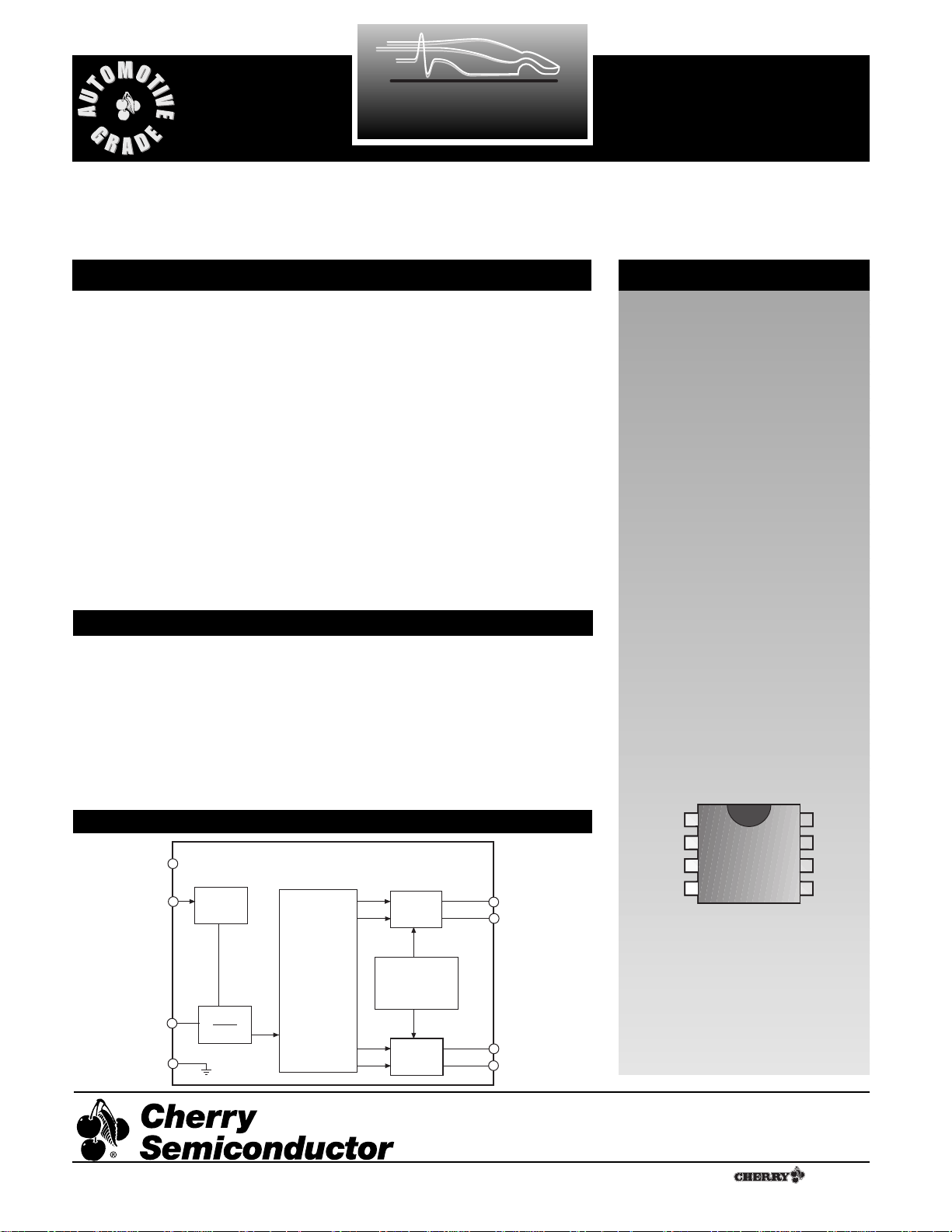
Block Diagram
Absolute Maximum Ratings
Supply Voltage (VCC) (continuous) -40ûC to +105ûC ......................Ð0.5 to 24V
(100ms pulse transient) -40ûC to +105ûC ..........................Ð0.5 to 60V
Input Voltage (VIN)..................................................................Ð0.3 to VCC+0.3V
Storage Temperature Range (T
STG
).............................................-65¡C to 150¡C
Junction Temperature Range.......................................................Ð40¡C to 150¡C
ESD (Human Body Model) .............................................................................2kV
Lead Temperature Soldering
Wave Solder(through hole styles only).............10 sec. max, 260¡C peak
Cherry Semiconductor Corporation
2000 South County Trail, East Greenwich, RI 02818
Tel: (401)885-3600 Fax: (401)885-5786
Email: info@cherry-semi.com
Web Site: www.cherry-semi.com
A Company
¨
Rev. 9/2/92
V
SENSOR
SELECT
Gnd
¸ 1
¸ 2
Sequencer
Coil
Driver
A
Overvoltage
and Short
Circuit
Protection
Coil
Driver
B
COILA+
COILA-
COILB
+
COILB-
CC
Input
Comp.

2
Electrical Characteristics: Unless otherwise stated, these specifications apply for Ð40¡C²TA²105¡C,6.5V²VCC²15.5V. All voltage
shall be referenced to Gnd unless otherwise noted. Overvoltage shutdown of coils occurs when V
CC
> 16V.
PARAMETER TEST CONDITIONS MIN TYP MAX UNIT
CS8441
* Voltage across the coils shall be measured at the specific voltages, but shall also be within linearly interpolated limits.
■ Supply, V
CC
Supply Voltage Range -40¡C ²TA²105¡C 6.5 15.5 VDC
-40¡C²TA²25¡C 6.5 24.0 VDC
Transient Pulse, 100ms 35.0 VDC
Supply Current VCC= 15.5 VDC 24 35 mA
Outputs not loaded
Overvoltage Shutdown 16 23 V
■ Speed Sensor Input, SENSOR
Input Frequency Range 0.2 1.0 kHz
Switching Threshold 1.2 2.4 VDC
Hysteresis 300 500 mVDC
Input Bias Current 0.8VDC²VIN²V
CC
0.1 ±1.0 µA
Input Voltage Range 0 V
CC
VDC
Operating Input Voltage 10k½ Resistor in Series -15 VDC
to V
CC
Input Clamp Current I Clamp at VIN= 0 VDC -0.4 -5.0 mA
■ Divider Select Input, SELECT
Logic 0 Input Voltage 100 mVDC
Logic 1 Input Voltage 3.0 VDC
Logic 0 Input Current 0V²VIN²100mV -1 -100 µA
Logic 1 Input Current 3V²VIN²15.5 VDC 0.75 2.00 mA
■ Coil Output Drivers
Coil Load +25¡C 198 210 222 ½
Coil Inductance 80 mH
Coil Resistance Temperature Coefficient 0.35 %/¡C
* Energized Coil Voltage
(Both Polarities) A and B VCC= 6.5 VDC VCC-1.5V VCC-0.9V VDC
VCC= 10.0 VDC VCC-1.6V VCC-1.0V VDC
VCC= 15.5 VDC-20¡C²TA²105¡C VCC-1.75V VCC-1.1V VDC
VCC= 15.5 VDC,Ð40¡C²TA²Ð20¡C VCC-2.0V VCC-1.2V VDC
De-Energized Coil Leakage ±100 µA
Current
■ Short Circuit Protection
Short Circuit Threshold 275 400 mA
I Coil A + I Coil B
Short Circuit Turn-Off Delay 5 µs
 Loading...