

Cherry Semiconductor CS8147YTVA5, CS8147YTHA5, CS8147YT5 Datasheet
■ Two Regulated Outputs
10V ± 5%; 500 mA
5V ± 3%; 70 mA
■ 70µA SLEEP Mode Current
■ Inherently Stable
Secondary Output
(No Output Capacitor
Required)
■ Fault Protection
Overvoltage Shutdown
Reverse Battery
60V Peak Transient
-50V Reverse Transient
Short Circuit
Thermal Shutdown
■ CMOS Compatible
Input with Low
(I
OUT(max)
) Input Current.
ENABLE
1
Features
Package Options
5 Lead TO-220
Tab (Gnd)
1
CS8147
10V/5V Low Dropout Dual Regulator
with
ENABLE
CS8147
Description
Block Diagram
Absolute Maximum Ratings
Input Voltage (V
IN
)
DC .............................................................................................-18V to 26V
Positive Peak Transient Voltage
(46V Load Dump @ VIN= 14V) .......................................................60V
Negative Peak Transient Voltage ......................................................-50V
ESD (Human Body Model) ...........................................................................2kV
Input...................................................................................-0.3 to 10V
Internal Power Dissipation..................................................Internally Limited
Junction Temperature Range...................................................-40¡C to +150¡C
Storage Temperature Range ....................................................-65¡C to +150¡C
Lead Temperature Soldering
Wave Solder (through hole styles only)..........10 sec. max, 260¡C peak
ENABLE
The CS8147 is a 10V/5V dual output linear regulator. The 10V ±.5%
output sources 500mA and the 5V
±3% output sources 70mA. The
secondary output is inherently stable and does not require an external
capacitor.
The on board function
controls the regulatorÕs two outputs. When is high, the
regulator is placed in SLEEP mode.
Both outputs are disabled and the
regulator draws only 70µA of quiescent current.
The regulator is protected against
overvoltage conditions. Both outputs are protected against short
circuit and thermal runaway
conditions.
The CS8147 is packaged in a 5 lead
TO-220 with copper tab. The copper tab can be connected to a heat
sink if necessary.
ENABLE
ENABLE
1
2 V
IN
3 Gnd
4V
OUT1
(10V)
5V
OUT2
(5V)
ENABLE
A Company
¨
Rev. 4/5/99
Cherry Semiconductor Corporation
2000 South County Trail, East Greenwich, RI 02818
Tel: (401)885-3600 Fax: (401)885-5786
Email: info@cherry-semi.com
Web Site: www.cherry-semi.com
V
IN
ENABLE
Pre-Regulator
+
Primary Output
Over Voltage
Shutdown
+
-
Anti-saturation
and
Current Limit
V
OUT1
Gnd
Bandgap
Reference
Thermal
Shutdown
Secondary Output
-
+
Current Limit
V
OUT2
2
CS8147
PARAMETER TEST CONDITIONS MIN TYP MAX UNIT
Electrical Characteristics for V
OUT
: VIN= 14V, I
OUT1
= I
OUT2
= 5mA, -40¡C < TJ< 150¡C, -40¡C ² TA² 125ûC,
= LOW; unless otherwise specified.
ENABLE
Package Lead Description
PACKAGE LEAD # LEAD SYMBOL FUNCTION
5 Lead TO-220
1 CMOS compatible input lead; switches V
OUT1
and V
OUT2
on
and off. When is low, V
OUT1
and V
OUT2
are active.
2V
IN
Supply voltage, usually direct from battery.
3 Gnd Ground connection.
4V
OUT1
Regulated output 10V, 500mA (typ)
5V
OUT2
Secondary output 5V, 70mA (typ).
ENABLE
ENABLE
■ Primary Output (V
OUT1
)
Output Voltage 13V ² V
IN
² 26V, I
OUT1
² 500mA, 9.50 10.00 10.50 V
Dropout Voltage I
OUT1
= 500mA 0.5 0.7 V
Line Regulation 11V ² V
IN
² 18V, I
OUT1
= 250mA 45 90 mV
Load Regulation 5mA ² I
OUT1
² 500mA 15 75 mV
Quiescent Current I
OUT1
² 1mA, No Load on V
OUT2
, V
IN
= 18V 3 7 mA
I
OUT1
= 500mA, No Load on V
OUT2
, V
IN
= 11V 60 120 mA
Quiescent Current = HIGH 70 200 µA
V
OUT1,VOUT2
= OFF
Current Limit 0.55 0.80 A
Long Term Stability 50 mV/khr
Over Voltage Shutdown V
OUT1
and V
OUT2
32 36 40 V
■ Secondary Output (V
OUT2
)
Output Voltage 6V ² V
IN
² 26V, 1mA ² I
OUT2
² 70mA 4.85 5.00 5.15 V
Dropout Voltage I
OUT2
² 70mA 1.5 2.5 V
Line Regulation 11 ² V
IN
² 18V, I
OUT
= 70µA 4 50 mV
Load Regulation 1mA ² I
OUT2
² 70mA, V
IN
= 14V 10 50 mV
Current Limit 150 mA
■ Function ( )
Input Threshold V
OUT2(ON)
1.40 2.50 V
V
OUT1(OFF)
.8 1.40 V
Input Current Input Voltage Range 0 to 5V -10 10 µA
ENABLE
ENABLE
ENABLE
ENABLE
ENABLE
3
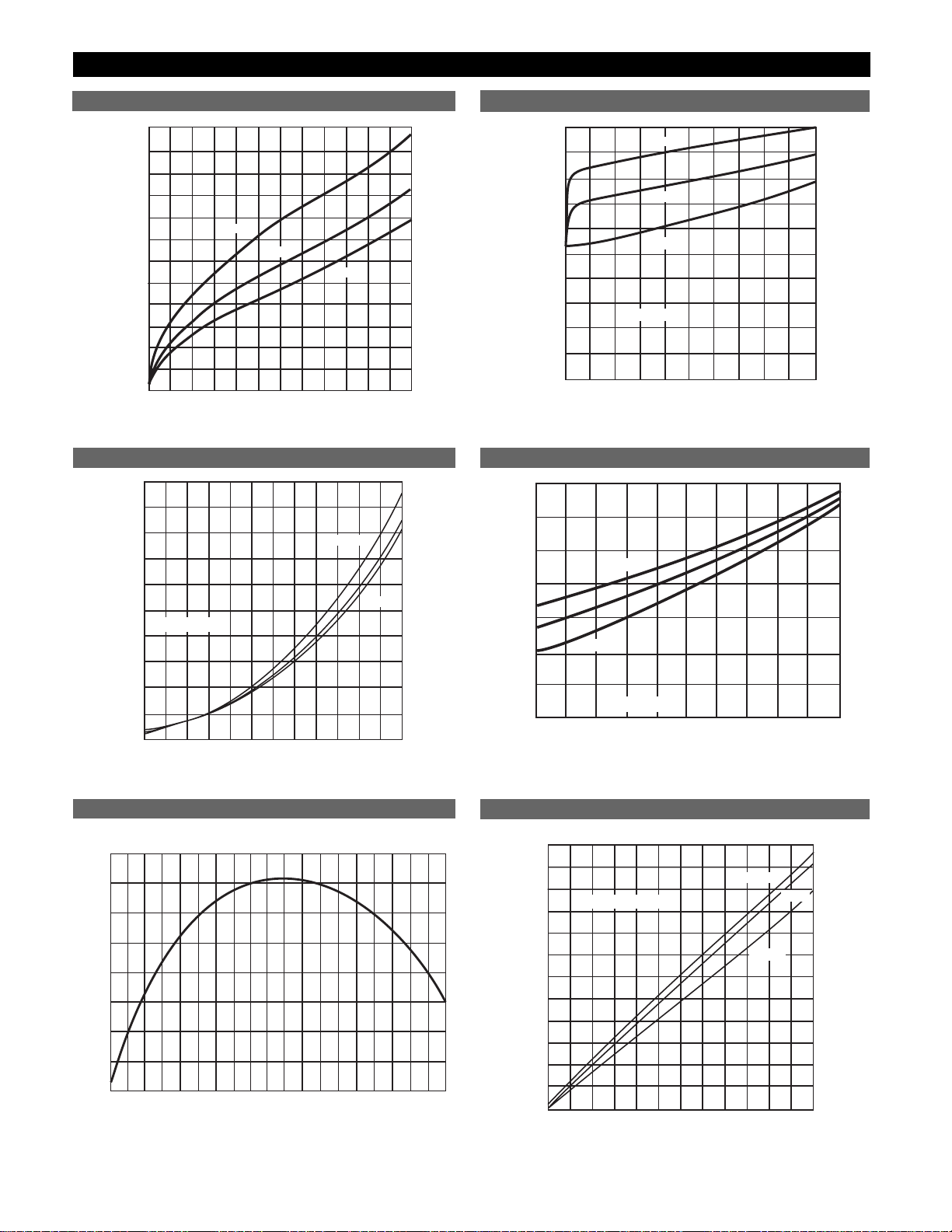
Typical Performance Characteristics
Output Current (mA)
Dropout Voltage (mV), V
OUT
1
0 50 100 150 200 300 350 400 450 500 550 600250
0
50
100
150
200
250
300
350
400
450
500
550
600
125°C
25°C
-40°C
Dropout Voltage vs. Output Current (V
OUT1
)
Output Current (mA) V
OUT2
(5V)
Dropout Voltage (V), V
OUT
2
0
10
0
0.20
125°C
25°C
-40°C
20 30 40 50 60 70 80 90 100
0.40
0.60
0.80
1.00
1.20
1.40
1.60
1.80
2.00
VIN = 6.00V
Output Current (mA)
Quiescent Current (mA)
0 50 100 150 200 300 350 400 450 500 550 600250
0
10
100
20
30
40
50
60
70
80
90
125°C
25°C
-40°C
V
IN
= 14V
Output Current (mA), V
OUT2
(5V)
Quiescent Current (mA)
0
10
0
1
125°C
25°C
-40°C
20 30 40 50 60 70 80 90 100
2
3
4
5
6
7
V
IN
= 14V
Quiescent Current vs. Output Current (V
OUT2
)
Quiescent Current vs. Output Current (V
OUT1
)
Dropout Voltage vs. Output Current (V
OUT2
)
Temp (C°)
PART1 V
IN
=14V, RLOAD=0
V
OUT
(Volts)
-50
4.98
4.99
5.00
5.01
5.02
-40 -30 -20 -10 0 10 20 30 40 50 60 80 90 100 110 120 13070 140
Output Current (mA), V
OUT
1
(10V)
Line Regulation (mV)
0 50 100 150 200 300 350 400 450 500 550 600250
0
10
100
20
30
40
50
60
70
80
90
-40°C
110
120
125°C
V
IN
= 11V - 26V
25°C
Line Regulation vs. Output Current (V
OUT1
)
V
OUT
2
vs. Temperature
CS8147
 Loading...