

Cherry Semiconductor CS464YDWR16, CS464YDW16, CS464 Datasheet

Features
■ 40mA Driver
■ Stall Timing
■ Output Clamp
■ Overvoltage Shutdown
Package Options
CS464
Single Coil Predriver
CS464
Description
The CS464, Single Coil Predriver,
provides interface control for the
current through a primary ignition coil. Features include output current control, input nega-
tive edge filtering, stall timing
and over-voltage shutdown. The
IC is available as a bumped flipchip or packaged in a 16 lead SO
wide package.
Application Diagram
Absolute Maximum Ratings
Lead Temperature Soldering
Reflow (SMD styles only)...........60 sec. max above 183¡C, 230¡C peak
Continuous Power Supply @ V
BAT
, -40¡C < TA< 55¡C .............5V to 24V
Continuous Power Supply @ V
BAT
, 55¡C < TA< 140¡C.............6V to 18V
Frequency .......................................................................................5 to 400Hz
Over the extended ranges of temperature, voltage, and frequency not
covered by normal operating conditions, low frequency and run related
functions are allowed an additional 20% on specification limits. The
degradation shall not be permanent, and upon returning to normal
operating conditions shall be within the specification limits. Non-normal ÒRun ModeÓ operation is 45 hours cumulative life not exceeding a
continuous run time of 10 minutes with a 10 minute ÒOffÓ time following each successive operating cycle.
MB
NC
NC
CR
IN+
NC
NC
Gnd
CS
S
NC
OUT
IC
D
NC
V
CC
Flip-Chip
1
16 Lead SO Wide
Rev. 3/1/99
Cherry Semiconductor Corporation
2000 South County Trail, East Greenwich, RI 02818
Tel: (401)885-3600 Fax: (401)885-5786
Email: info@cherry-semi.com
Web Site: www.cherry-semi.com
A Company
¨
1
12V
V
BAT
CS
0.47mF
50V
RIC1
200
RIC2
4k
Adjust for 6.5A Coil Current
RS156RS2
N1
N2
0.05W, 5W
MB
CS
NC
NC
CR
0.1mF
50V
CR
IN+
NC
NC
Gnd
RIN+
V
IN
10k
RMB
10.7k
0V
40Hz
CS464
OUT
S
NC
IC
D
NC
V
CC
ZD
18V
CV
0.1mF
CC
RD, 55W, 5W
, 330
RV
CC
CS464
2
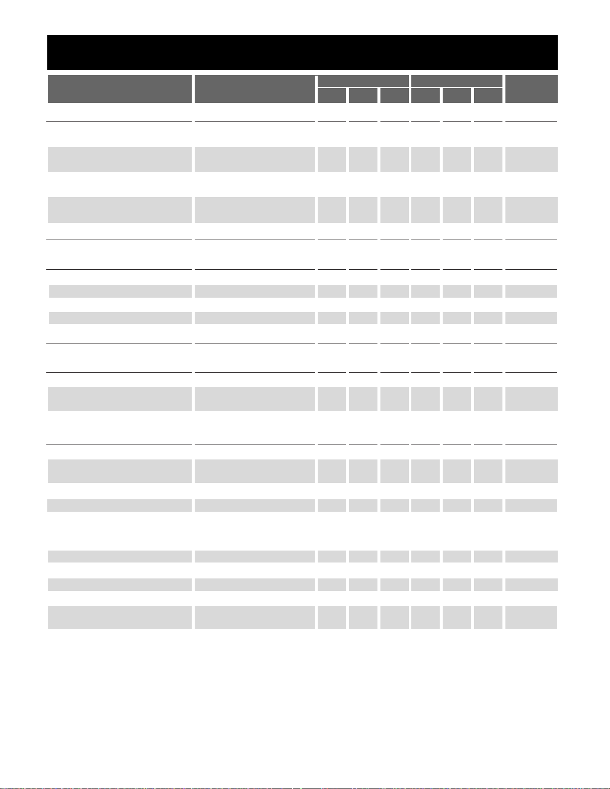
Electrical Characteristics: -30¡C ² TA² 125¡C; -30¡C < TJ< 125¡C; All Parameters after VCCPower-up > 100ms;
V
BAT
= 14V unless otherwise specified.
16 Lead SO Wide Flip Chip
PARAMETER TEST CONDITIONS MIN TYP MAX MIN TYP MAX UNIT
■ Input, Current, Delay
Positive Threshold V
BAT
= 6V 56.2 66 56.2 66 % of V
BAT
V
BAT
= 16V 56.2 66 56.2 66 % of V
BAT
Hysteresis V
BAT
= 6V 8 20.2 9 20.2 % of V
BAT
V
BAT
= 16V 8 20.2 9 20.2 % of V
BAT
I
CC
V
BAT
= 6V 1 2.75 4.5 1 2.75 4.5 mA
V
BAT
= 16V 5 12 19 5 12 19 mA
Input Impedance @10µA 70 170 400 k½
@0.1mA 70 170 400 k½
IC Process Delay 15 15 µs
■ Output
Output Current V
BAT
= 6V, 2.1V output load 40 52.5 65 40 52.5 65 mA
Output SOA Current V
BAT
= 22V (Note 1) 40 52.5 65 40 52.5 65 mA
Output Leakage Current V
BAT
= 25V (Note 1) 0 100 0 100 µA
Output Clamp Voltage @ 10mA 13.7 15.35 17 13.7 15.35 17 V
Output Clamp Impedance @ 10mA 10 42.5 80 10 42.5 80 ½
■ Regulation Voltage
VS Regulation Voltage V
BAT
= 7.8V 165 200 235 165 200 235 mV
VS Supply Rejection V
BAT
= 6V ~ 22V (Note 1) 0 0 14 0 0 14 %
V
BAT
= 7.8V ~ 22V (Note 1) 0 0 13 0 0 13 %
■ Stall & Protection
Stall Shutdown VS V
BAT
= 6V -5 0 5 -1 0 1 mV
Stall Shutdown Frequency V
BAT
= 14V .4 .4 Hz
V
BAT
= 5.5V 1.4 1.47 1.4 1.47 Hz
Stall Shutdown Time V
BAT
= 6V 19 28 37 19 28 37 ms
Stall to Spark Output Delay 4.6 6.7 9.5 4.6 6.7 9.5 ms
I/O Signal Relationship @ 80% Input 79.0 80.5 82.0 79.0 80.0 81.0 %
@ 50% Input 49.0 50.5 52.0 49.0 50.0 51.0 %
@ 30% Input 29.0 30.5 32.0 29.0 30.0 31.0 %
Battery Interrupt Time 25 750 25 750 ms
Battery Interrupt Recovery Time @ 200Hz 800 800 ms
High Voltage Shutdown 25 28 32 25 28 31 V
High Frequency Cut off 1 2.5 5 1 2.5 5 kHz
Negative Threshold V
BAT
= 6V 28 36 30 36 % of V
BAT
V
BAT
= 16V 28 36 30 36 % of V
BAT
Note 1: Voltage extremes are for testing purposes only. Part in continuous operation should conform to absolute max
table.
 Loading...