

Cherry Semiconductor CS3720XVA17, CS3720XTHA7, CS3720XT7, CS3720XM7, CS3720XDPSR7 Datasheet
...
1
Features
COIL +
Q
1
COIL -
V
SS
ENABLE1
ENABLE2
DIRECTION
Gnd
DRIVE
CONTROL
LOGIC
OUTPUT
DRIVER
Ð
OUTPUT
DRIVER
+
OUTPUT
DRIVER
+
Overvoltage
Protection
Transient
Protection
V
REF
Over
Current
Protection
Q
3
Q
4
Q
2
Over
Current
Protection
■ High Current (2A typ)
Output
■ TTL compatible
DIRECTION Control
■ Fault Protection
Overvoltage
Load Dump Protection to
74V
Package Options
7 Lead Power SIP
CS3720
2A H-Bridge Driver
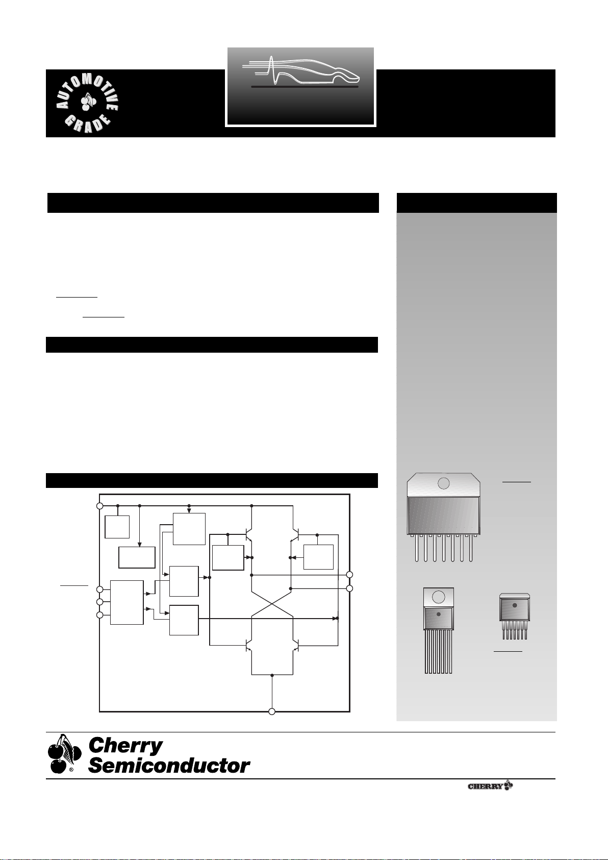
Description
Block Diagram
The CS3720 is high current (2A typ)
bidirectional DC motor driver. The
H-bridge output stage consists of
two pairs of power NPN transistors, each with a V
SAT
=2.3V at
I
OUT
=2A (typ).
The three TTL compatible inputs,
ENABLE1, ENABLE2, and DIRECTION control the output stage.
When ENABLE1 is low and
ENABLE2 is high, DIRECTION
determines which way current
flows through the motor coil. Any
other combination of ENABLE settings disables the outputs.
The CS3720 is protected against
overvoltage fault conditions. If a
fault condition is detected, the IC
shuts down.
CS3720
2 ENABLE1
4 DIRECTION
6 COIL+
8 Gnd
10 COILÐ
12 V
SS
14 ENABLE2
Absolute Maximum Ratings
DC Input Voltage ..................................................................................-0.3 to 28V
Transient Input Voltage ...................................................................... -0.3 to 74V
Internal Power Dissipation......................................................Internally limited
Junction Temperature Range .....................................................-40¡C to +150¡C
Storage Temperature Range.......................................................-65¡C to +150¡C
Lead Temperature Soldering
Wave Solder (through hole styles only) ............10 sec. max, 260¡C peak
Reflow (SMD styles only).............60 sec. max above 183¡C, 230¡C peak
Electrostatic Discharge (Human Body Model).............................................2kV
1
7 Lead TO-220
7 Lead D
2
PAK
1
1 ENABLE1
2 DIRECTION
3 COIL+
4 Gnd
5V
SS
6 COILÐ
7 ENABLE2
Rev. 5/4/99
Cherry Semiconductor Corporation
2000 South County Trail, East Greenwich, RI 02818
Tel: (401)885-3600 Fax: (401)885-5786
Email: info@cherry-semi.com
Web Site: www.cherry-semi.com
A Company
¨
2
Current flow through the two outputs COIL+ and COILis controlled by the combined settings of ENABLE1,
ENABLE2 and DIRECTION (Table 1). The outputs will be
active only when ENABLE1 is low and ENABLE2 is high.
When DIRECTION is high, current flows out of COIL+
and into COIL-. When DIRECTION is low, current flows
out of COIL- and into COIL+. For any other combination
of ENABLE settings, the outputs are off.
Table 1. Logical Control Diagram
ENABLE1 ENABLE2 DIRECTION COIL+ COIL-
Low High High High Low
Low High Low Low High
High X X OFF OFF
X Low X OFF OFF
Motor Direction Control
Electrical Characteristics: 5.5V ² V
CC
² 17V; Ð40¡C ² TJ ² +150¡C; Ð40¡C ² TC ² +105¡C; Ð40¡C ² TA² 105¡C; unless otherwise specified.
PARAMETER TEST CONDITIONS MIN TYP MAX UNIT
CS3720
Package Lead Description
PACKAGE LEAD# LEAD SYMBOL FUNCTION
Application Hints
15 Lead 7 Lead 7 Lead
Power SIP TO-220 D2PAK
2 1 1 ENABLE1 Enables output when held low and ENABLE 2 = High
4 2 2 DIRECTION Determines the direction of current flow through COIL+ and
COIL- as long as ENABLE1 = Low and ENABLE2 = High
6 3 3 COIL+ Positive Output of H bridge to coil
8 4 4 Gnd Ground connection
12 5 5 V
SS
Supply voltage for IC
10 6 6 COIL- Negative Output of H bridge to coil
14 7 7 ENABLE2 Enables output when held high and ENABLE 1 = Low
■ Output Stage
Quiescent Current I
OUT
=0mA; 10 mA
ENABLE1=DIRECTION= High
ENABLE2=Low
Output Saturation Voltage I
OUT
=2A 3.2 V
I
OUT
=500mA 2.6 V
Output Leakage Current I
OUT
=0mA 20 µA
Current Limit 3.0 A
■ Logic Control Functions
High Level Input Voltage 2.0 V
Low Level Input Voltage 0.8 V
High Level Input Current 10 µA
Low Level Input Current -250 µA
Turn on Delay R
LOAD
=30½; Coil=5mH; 50 µs
Guaranteed by design C
LOAD
=15pF 5
Turn off Delay R
LOAD
=30½; Coil=5mH; 50 µs
Guaranteed by design C
LOAD
=15pF 5
■ Fault Protection Functions
Overvoltage Shutdown I
OUT
= 500mA 18.0 21.5 V
 Loading...