

Cherry Semiconductor CS291N14, CS291DWR16, CS291DW16, CS290N14, CS290DWR16 Datasheet
...
Features
■ 40mA Driver
■ Stall Timing
■ Output Current Control
■ Output Clamp
■ Overvoltage Shutdown
Package Options
CS290/291
Ignition Controller
CS290/291
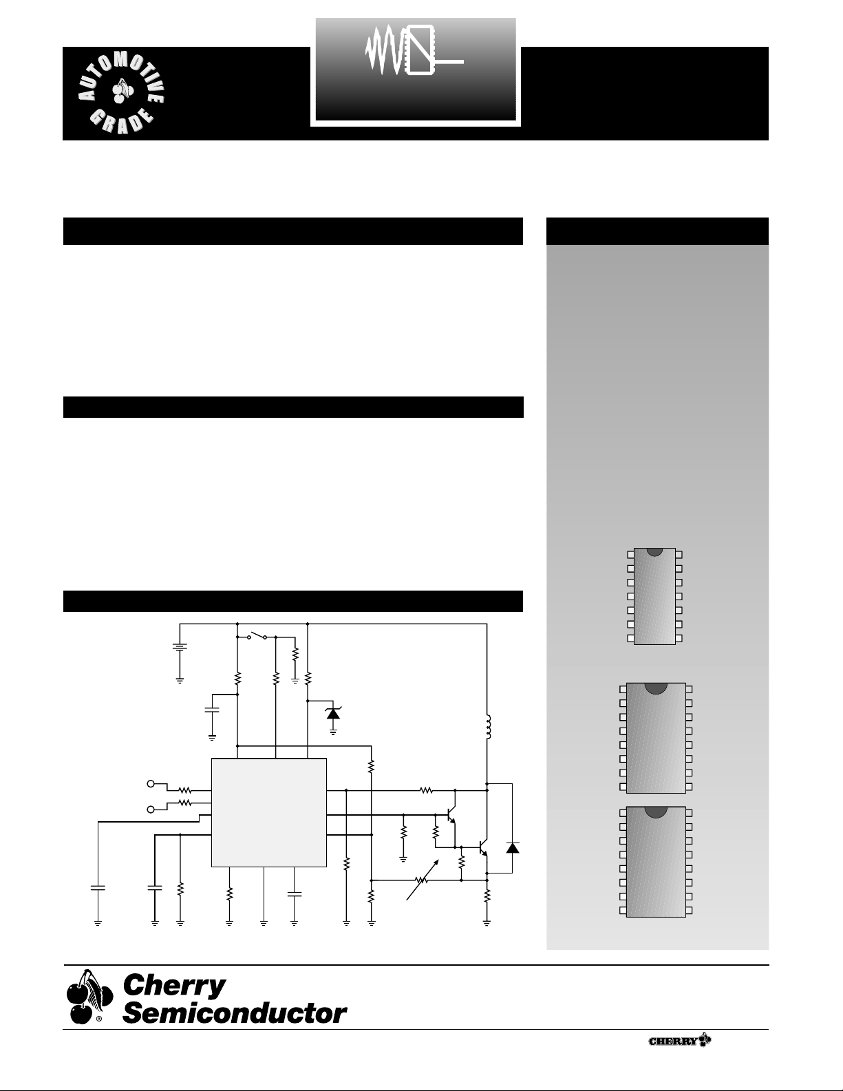
Description
The CS290/291 are integrated circuits to be used in the automotive
ignition system. The application
diagram shown below highlights
the CS290. The CS291 is identical
with the differential input replaced
by a single-ended input. The part is
capable of withstanding 90V load
dump transients in the circuit
shown below. The part is also
reverse battery protected.
Application Diagram
Absolute Maximum Ratings
Power supply voltage, V
BAT
. . . . . . . . . . . . . . . . . . . . . . . . . . . . . . .−0.3V to 22V
Peak Transient Voltage (Load Dump 76V @ 14V V
BAT
) . . . . . . . . . . . . . . . .90V
Storage Temperature . . . . . . . . . . . . . . . . . . . . . . . . . . . . . . . . . . .−55°C to 165°C
Operating Junction Temperature, T
J
. . . . . . . . . . . . . . . . . . . . . . . . . . . . . .150°C
Lead Temperature Soldering
Wave Solder (through hole styles only) . . . . . . .10 sec. max, 260°C peak
Reflow (SMD styles only) . . . . . . .60 sec. max above 183°C, 230°C peak
Gnd
MB
AC
25/75
V
IN+
V
IN−
Start V
CC
D
CVS
OUT
NC
CS
BI
14 Lead PDIP
1
16 Lead SO Wide
A Company
®
Rev. 3/8/99
Gnd
MB
AC
25/75
V
IN+
V
IN−
Start V
CC
D
CVS
OUT
NC
CS
BI
NC NC
Gnd
MB
AC
25/75
V
IN−
Start V
CC
D
CVS
OUT
TEST
CS
BI
NC NC
NC
Consult Factory for Flip Chip
CS290
CS291
Cherry Semiconductor Corporation
2000 South County Trail, East Greenwich, RI 02818
Tel: (401)885-3600 Fax: (401)885-5786
Email: info@cherry-semi.com
Web Site: www.cherry-semi.com
V
BAT
1k
1
V
V
C
RUN
0.1µF
C
ADAPTIVE
0.1µF
IN+
IN−
0.1µF
5k
5k
3.2M
(optional)
330 27k
V
Start D
CC
IN+
IN−
CS290
25/75
AC
MB Gnd BI
15.3k
55
CVS
OUT
CS
C
STALL
0.1µF
18V
16k
200
200
56
4k
Adjust for 6.5A (max)
Coil Current
Ignition
Coil
0.05
1
1

■ Input
Positive Threshold 66 %V
BAT
Negative Threshold V
BAT
=16V 29 %V
BAT
V
BAT
= 6V 29
Hysteresis 9%V
BAT
Input Impedance Input = 100µA 70 325 kΩ
VCCNegative Edge Filter V
BAT
= 16V 18 1100 µs
V
BAT
= 6V 4 1100
■ Output Stage
Negative Edge Delay V
BAT
= 6V 1.1 3.1 ms
(Start Mode)
Positive Edge Delay V
BAT
= 5V 1.06 1.80 ms
(Start Mode)
Delay Time V
BAT
= 14V 0 16 µs
(Start High to Output Low)
Output Current V
BAT
= 6V 40 65 mA
Output SOA V
BAT
= 22V 40 65 mA
Output Leakage V
BAT
= 18V 0 100 uA
Output Clamp Voltage Output = 10mA 13.7 17 V
Output Clamp Impedance Output = 10mA 10 80 Ω
(Refers to Collector Sense Voltage pin)
High Frequency On Time V
BAT
= 14V 70 80 %
■ General
I
CC
V
BAT
= 6V 1.4 4.6 mA
V
BAT
= 16V 5 19
AC Gain V
BAT
= 14V 0.8 1.2 V/V
Adaptive Cap Gain
VCSRegulation V
BAT
= 6V 140 210 mV
High Voltage Shutdown 24.3 31 V
■ Stall
V
STALL
Soft Shutdown Voltage VCS= 6V 0 11 mV
Soft Shutdown Frequency V
BAT
= 14V 1.0 2.6 Hz
Soft Shutdown Time V
BAT
= 6V 13.1 27 ms
Stall to Spark Output Delay V
BAT
= 14V 4.5 8.9 ms
Battery Interrupt Time V
BAT
= 14V 25 750 ms
Battery Interrupt Recovery Time (200 Hz) 0 800 ms
■ Dwell
Dwell @ 10Hz V
BAT
= 5V 46 54 %
(Start Mode)
Start to Output Disable Time V
BAT
= 14V 65 135 ms
Excess Dwell @ 20Hz V
BAT
= 14V 14 20.8 %
(Run Mode)
PARAMETER TEST CONDITIONS MIN TYP MAX UNIT
2
Electrical Characteristics: 6V < VB< 16V, −30°C < TA< 125°C
CS290/291
 Loading...