

Cherry Semiconductor CS209AYN8, CS209AYDR8, CS209AYDR14, CS209AYD8, CS209AYD14 Datasheet
1
Features
■ Separate Current
Regulator for Oscillator
■ Negative Transient
Suppression
■ Variable Low-Level
Feedback
■ Improved Performance
over Temperature
■ 6mA Supply Current
Consumption at
V
CC
= 12V
■ Output Current Sink
Capability
20mA at 4V
CC
100mA at 24V
CC
Package Options
8L PDIP & SO
14L SO
CS209A
Proximity Detector
7
8
1
2
3
4
5
6
OSC
TANK
Gnd
OUT
1
RF
V
CC
DEMOD
OUT
2
10
7
14
13
12
8
1
2
3
4
5
6
11
9
OSC
TANK
Gnd
OUT
1
N.C.
OUT
2
N.C.
N.C.
RF
V
CC
N.C.
DEMOD
N.C.
N.C.
CS209A
Description
The CS209A is a bipolar monolithic
integrated circuit for use in metal detection/proximity sensing applications.
The IC (see block diagram) contains two
on-chip current regulators, oscillator
and low-level feedback circuitry, peak
detection/demodulation circuit, a comparator and two complementary output
stages.
The oscillator, along with an external
LC network, provides controlled oscillations where amplitude is highly dependent on the Q of the LC tank. During
low Q conditions, a variable low-level
feedback circuit provides drive to maintain oscillation. The peak demodulator
senses the negative portion of the oscillator envelop and provides a demodulated waveform as input to the comparator. The comparator sets the states
of the complementary outputs by comparing the input from the demodulator
to an internal reference. External loads
are required for the output pins.
A transient suppression circuit is
included to absorb negative transients
at the tank circuit terminal.
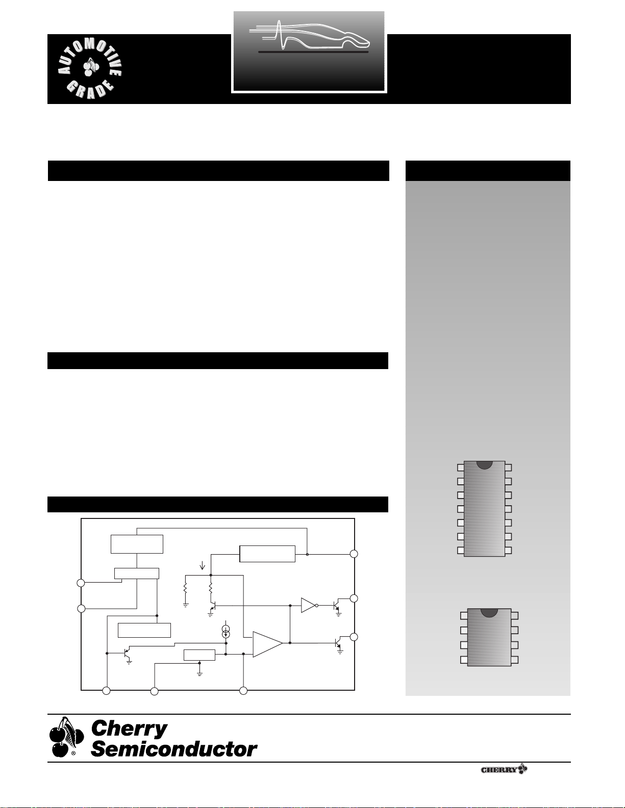
Block Diagram
Absolute Maximum Ratings
Supply Voltage ................................................................................................24V
Power Dissipation (TA= 125¡C).............................................................200mW
Storage Temperature Range ....................................................Ð55¡C to +165¡C
Junction Temperature...............................................................Ð40¡C to +150¡C
Electrostatic Discharge (except TANK pin) ................................................2kV
Lead Temperature Soldering
Wave Solder(through hole styles only) ...........10 sec. max, 260¡C peak
Reflow (SMD styles only)...........60 sec. max above 183¡C, 230¡C peak
A Company
¨
Rev. 3/11/99
Cherry Semiconductor Corporation
2000 South County Trail, East Greenwich, RI 02818
Tel: (401)885-3600 Fax: (401)885-5786
Email: info@cherry-semi.com
Web Site: www.cherry-semi.com
OSC
RF
DVBE/R Current
Regulator
Oscillator
OSC
Feedback
Neg Transient
Suppression
TANK DEMOD
GND
4.8kW
300mA
23.6kW
DEMOD
V
CC
VBE/R Current
Regulator
+
COMP
-
V
CC
OUT
1
OUT
2

2
Electrical Characteristics: -40¡C ² TA² 125¡C unless otherwise specified
PARAMETER TEST CONDITIONS MIN TYP MAX UNIT
CS209A
8
6
4
2
100
4
8
12 16 20
Switching Delay (ms)
Output Load (kW)
(T = 22°C, VCC= 12V)
Output Switching Delay vs. Temperature
Output Switching Delay vs. Output Load
Typical Performance Characteristics
Package Pin Description
PACKAGE PIN# PIN SYMBOL FUNCTION
8L PDIP & SO 14L SO
1 1 OSC Adjustable feedback resistor connected between OSC and
RF sets detection range.
2 2 TANK Connects to parallel tank circuit.
3 3 Gnd Ground connection.
4 4 OUT
1
Complementary open collector output; When OUT1=
LOW, metal is present.
5 6 OUT
2
Complementary open collector output; When OUT2=
HIGH, metal is present.
6 10 DEMOD Input to comparator controlling OUT
1
and OUT2.
712V
CC
Supply voltage.
8 13 RF Adjustable feedback resistor connected between OSC and
RF set detection range.
5,7,8,9,11,14 NC No Connection.
Supply Current I
CC
VCC= 4V 3.5 6.0 mA
V
CC
= 12V 6.0 11.6 mA
V
CC
= 24V 11.0 20.0 mA
Tank Current V
CC
= 20V -550 -300 -100 µA
Demodulator Charge Current V
CC
= 20V -60 -30 -10 µA
Output Leakage Current V
CC
= 24V 0.01 10.00 µA
Output V
SAT
VCC= 4V, IS =20mA 60 200 mV
V
CC
= 24V, IS =100mA 200 500 mv
Oscillator Bias V
CC
= 20V 1.1 1.9 2.5 V
Feedback Bias V
CC
= 20V 1.1 1.9 2.5 V
Osc - Rf Bias V
CC
= 20V -250 100 550 mV
Protect Voltage I
TANK
= -10mA -10.0 -8.9 -7.0 V
Detect Threshold 720 1440 1950 mV
Release Threshold 550 1200 1700 mV
6.5
(VCC = 12V, R
5.5
4.5
Switching Delay (ms)
3.5
2.5
-40 -20 0 20 40 60 80 100 120
load
= 1kW)
Temperature (°C)
 Loading...