

Page 1
GH-780
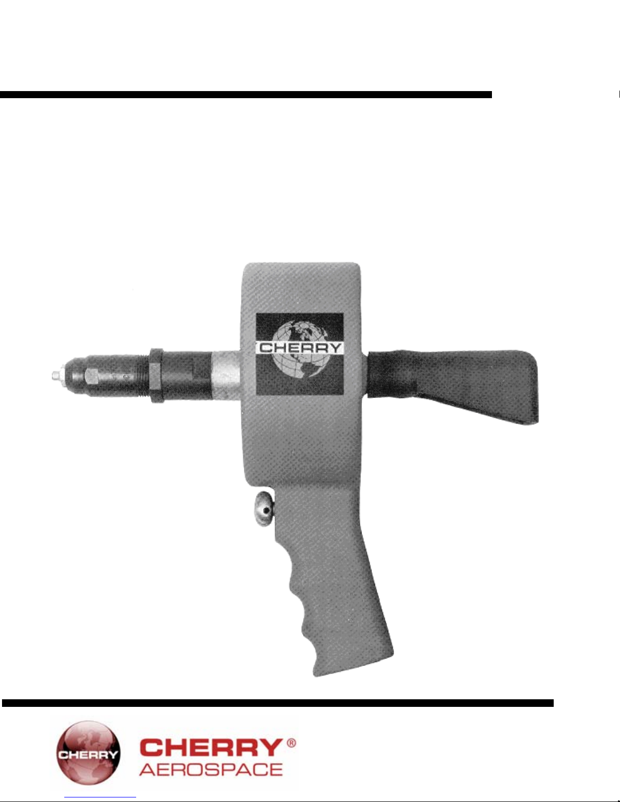
Pneumatic Power Riveter
MAINTENANCE MANUAL
1224 East Warner Ave,
Santa Ana, CA 92705
Tel: 1-714-545-5511
Fax: 1-714-850-6093
www.cherryaerospace.com
Page 2

THE GH-780 POWER RIVETER
TABLE OF CONTENTS
Description .........................................................................3
Specifications for GH-780..................................................3
Safety Warnings.................................................................3
How to use the GH-780 .....................................................4
Maintenance and Repair ...................................................4
Trouble Shooting................................................................4
Overhaul.............................................................................4
Air Valve..................................................................4
Housing ...................................................................5
H703 & H743A Pulling Heads ...........................................5
Cross Sectional Drawing of GH-780 Power Riveter.........6
Parts List for the GH-780 Power Riveter...........................7
Exploded View of GH -780 .................................................7
Limited Warranty...............................................Back Cover
2
Page 3
g
DESCRIPTION
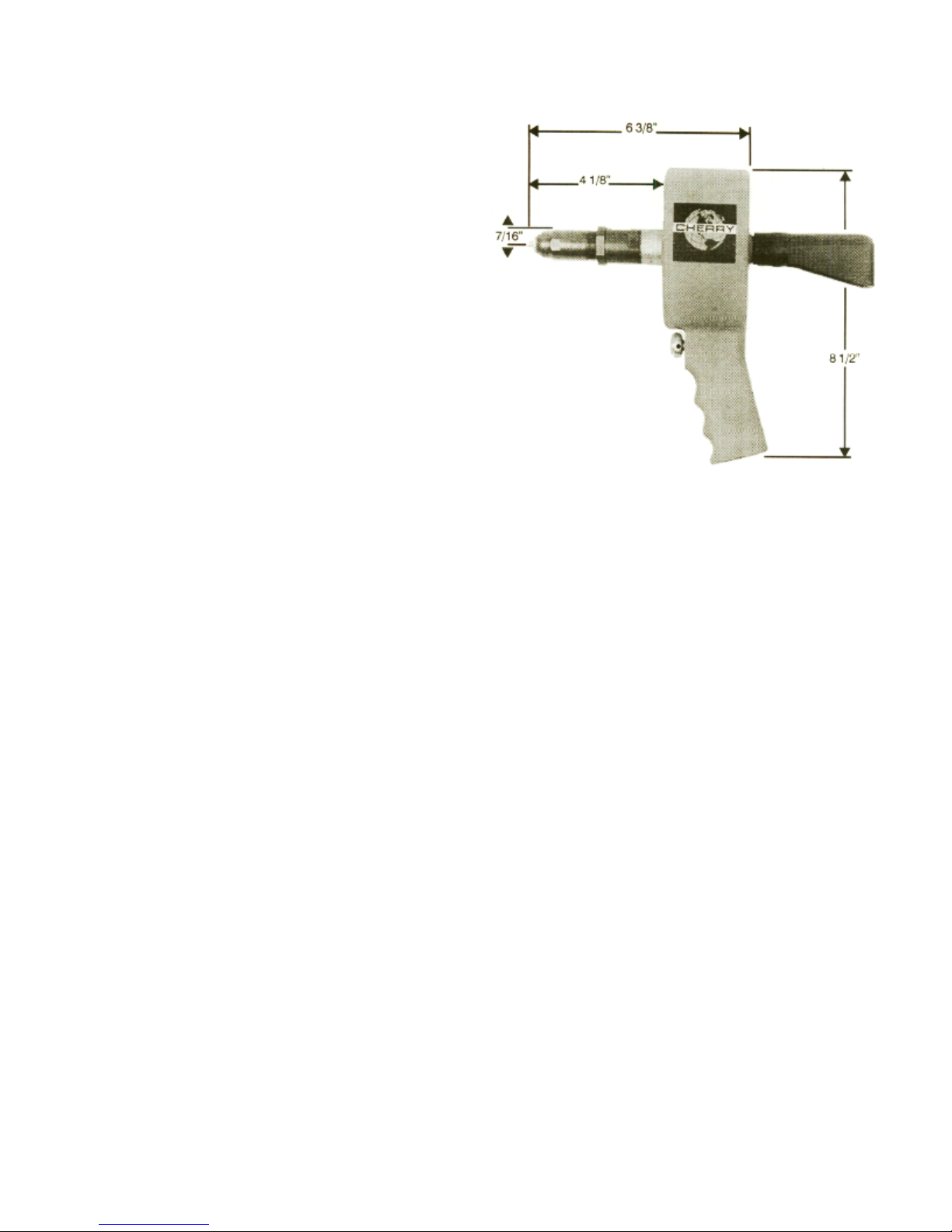
The Cherry® GH-780 is a pneumatic tool designed sp ecifically
for the most efficient installation of Commercial fasteners. It
weighs only 3 pounds and can b e operated in any positi on with
one hand.
SPECIFICATIONS FOR GH-780
Cherry® Aerospace’s policy is one of continuous
development. Specifications shown in this document may
be subject to change which may be introduced after
publication. For the latest information always consult
Cherry® Aerospace.
AIR PRESSURE 90 PSI (6,2 bar) Min./120 PSI (8,3 bar) Max.
STROKE 1.125" (28,6 mm)
PULLING FORCE 1100 lbs. (4,95 kN) @ 90 PSI (6,2 bar)
CYCLE TIME Approximately One Second
WEIGHT* 2.9 Pounds (1,32 kg)
NOISE LEVEL 65 Db (A)
VIBRATION Less than 2,5 m/s
AIR CONSUMPTION 0.10 SCF/cy cl e ( 2 ,8 3 L /cycle)
*without pulling head
2
SAFETY WARNINGS
• Operating this tool with a damaged or missing stem defle ctor, or using the deflector as a handle, may result in severe
personal injury. The pin deflector should be rotated until t he
aperture is facing away from the operator and other persons
working in the vicinity.
• Approved eye protection should be worn when operating,
repairing, or overhauling this tool.
• Do not use beyond the design intent.
• Do not use substitute compon ents for repair.
• Any modification to the tool, pulli ng heads, accessories or
any component supplied by Cherry® Aerospace, or their
representatives, shall be the customer's entire
responsibility. Cherry® Aerospace will be pleased to advise
on any proposed modification.
• The tool must be maintained in a safe working condition at
all times and examined at regular intervals for damage.
• Before disassemblin g the tool for repair, refer to the maintenance instructions. All repairs shall be undertaken only by
personnel trained in Cherry® Aerospace installation tools.
Contact Cherry® Aerospace with your training
requirement.
• Always disconnect the air line from the tool inlet before
attempting to service, adjust, fit or remove any accessory.
• Do not operate the tool when it is directed at any person.
• Ensure that the vent holes do not become blocked or
covered and that all hoses are always in good condition.
• Operating air pressure should not exceed 120 psi (7,6 bar)
• Do not operate the tool without pulling head in place.
• Do not operate the tool un less the nose plate (4) is fully
secured by the retaining ring (3).
• All retaining rings, screwed end caps, air fittings, hoses,
hose fittings, trigger valves and pulling heads should be
attached securely and examined at the end of each working
shift.
• Do not pull fast eners in the air.
• The precautio ns to be used when using this tool must be
explained by the customer to all operators. Any question
regarding the correct operation of the tool and operator
safety should be directed to Cherry® Aerospace.
• Do not pound on the rear of the tool head to force fasteners
into holes as this will dama
e the tool.
3
Page 4
A
j
p
HOW TO USE THE GH-780
ttach the proper pulling head securely to the GH780 (see
Pulling Heads, page 5). Insert the rivet stem into the pulling
head until the head of the rivet is in contact with the pulling
head sleeve. This will ensure full engagement between the
aws and the rivet stem and will prevent slippage.
MAINTENANCE AND REPAIR
The GH-780 has been manufactured to give maximum
service with minimum care. In order that this may be
accomplished, the following recommendations should be
followed.
1. Keep excessive moisture and dirt out of air supply to
revent wear.
TROUBLESHOOTING
1. Air line pressure should be maintained at 90 to 120 psi at
the riveter. The air line should be equipped with a filter to
keep excessive moisture and dirt out of the air suppl y. This
will prevent clogging of the ports in the air valve spool and
sleeve.
2. All pulling head parts should be firmly attached. Loose
parts will affect the performance of the tool.
3. If riveter cycles slowly, the cause is usually insufficient air
pressure. Check it with the pressure gauge. It must be 90
to 120 psi. If air pressure is sufficient, the tool should be
cleaned out to remove any dirt which may be blocking the
air passages. Another cause of slow cycling could be lack
of lubricant on the O-rings. See the overhaul section.
4. Air exhaust is from the bottom of the handle. If air escapes
from the front or rear of the tool, the O-rings are either
worn or damaged and should be replaced.
5. If the tool appears to have excessive recoil motion, the air
pressure is probably too high. Check with a pressure
gauge, and if it is over 120 psi, it should be reduced. Too
much air pressure can adversely affect the O-rings.
Insert the rivet into the application and pull the trigger to activate the tool. Upon release of the trigger, the stem will
release to the rear of the tool. Ensure that the pin deflector (12)
is in place. To prevent FOD (foreign object debris), use a
mandrel catcher bag (13). (Must be ordered separately).
2. Do not pound on the rear of the tool head to force
rivets into holes, as this will damage the tool.
3. Make sure the pulling head is correctly and securely
attached.
6. If the tool does not set rivets correctly, the trouble may
be in the pulling head rather than the riveter. It may be
due to worn jaws or a weak jaw spring. See the pulling
head section.
Virtually all the moving parts in this tool ride on O-rings. This
means no metal to metal wear. By the use of close tolerances
and low micro-inch surfaces against which t he O-rings seal, a
long life can be expected before any overhaul becomes necessary. At that time, a complete overhaul can be achiev ed by
the use of Service Kits G780KS, which contains a complete set
of O-rings.
G780KS SERVICE KIT
QTY PART NO. ITEM
1 670B31 Rod, Piston
3 P-293 O-Ring
1 P-507 O-Ring
2 P-508 O-Ring
1 P-534 O-Ring
1 TMAN GH-780 Parts List & Manual
OVERHAUL
The disassembly and re-assembly procedures can b e accomplished by utilizing the following instructions and the dra wings
on pages 6 and 7. Use extreme care during disassembly
and re-assembly not to mar, nick or burr any smooth
AIR VALVE
• To disassemble, first disconnect tool from its air source.
• Remove the trigger (14) an d retaining ring (16). Next, remove
Level-seal plug (19). The valve spool can then be pushed out,
from front to rear. The valve sleeve is pressed into the
housing and should not be removed. If ports in the sleeve
appear to be clogged, dip the handle in a solvent and blow air
into it to free any accumulation of oil and dirt.
• Re-assembly of the air valve begins with new O-rings (17)
on the valve spool (18). Lubricate with a clear grease suc h
as Parker O-Lube, then insert into the handle of housing
surface that comes in contact with O-rings. Before
installing O-rings, be sure to apply an O-ring lubricant such as
Parker O-Lube to the surface.
from the rear. Use care not to damage O-rings by keeping
them centered. Push in as far as possible until the small
diameter of the valve spool comes out of the front.
• Next, using T eflon tap e or pipe joint compound on threads,
insert a Level-seal plug (19) and tighten firmly. The retaining
ring (16) is put into the groove of the small diameter of the
valve spool (18) and then the trigger (14) is put on the small
diameter of the valve spool and tightened with an allen
wrench on the set screw (15).
4
Page 5
HOUSING
• Disconnect riveter from the air line and remove the pulling
head before attempting disassembly of housing. If piston rod
(1) turns with pulling head, hold it by applying open-end
wrench to flats on end of rod.
• Remove retaining ring (3) using narrow bladed screwdriver.
Rubber deflector (12) should also be removed.
• Insert a steel bar approximately 1/2" diameter by about four
inches long through the rear opening until it is solidly against
the end of the drawbolt (9). Strike the end of the steel bar with
a hammer, using sufficient force to drive the entire nose
plate/piston assembly out of the housing.
• Check rubber cushion (10) and replace if it is flattened thinner than the recess in the piston. Examine all O-rings for
wear or damage and replace where necessary. O-rings (5,
8 & 6-rear) are easily replaced, but to replace the O-ring (6front) in the nose plate (4), further disassembly of the nose
plate/piston assembly is necessary. Insert a 5/16" hex
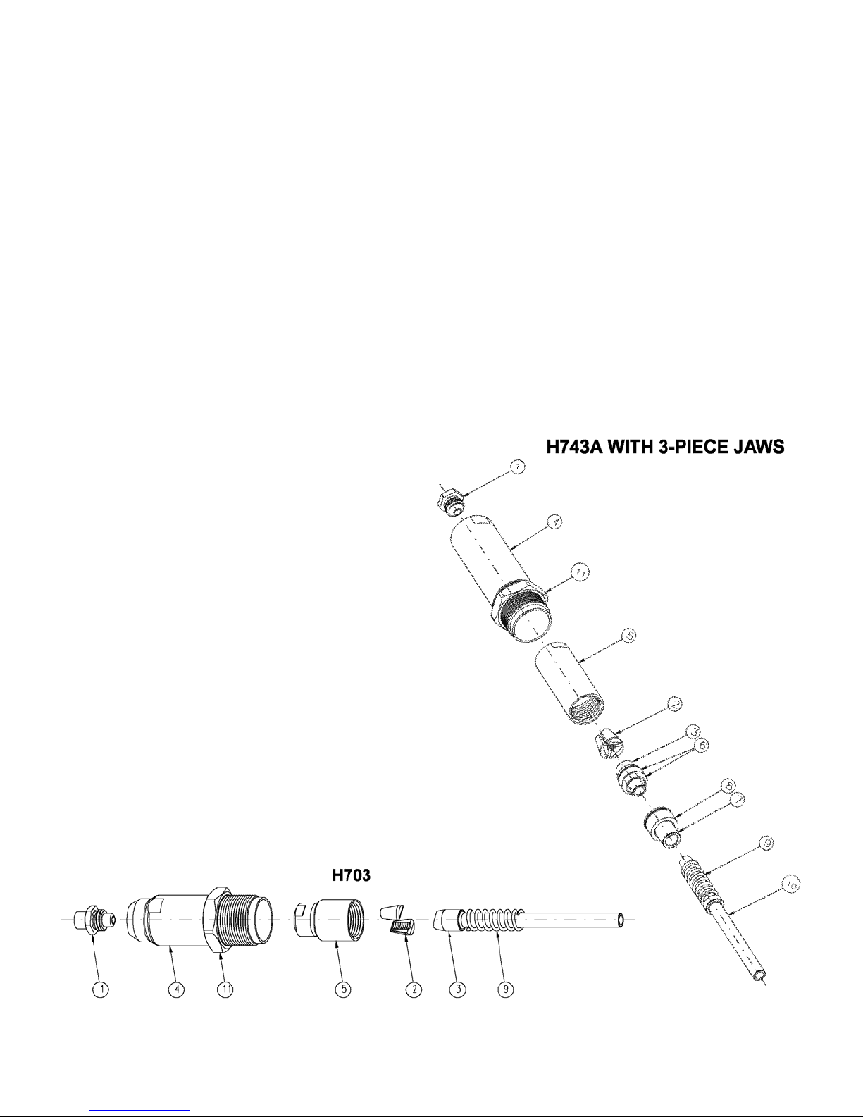
H703 & H743A PULLING HEADS
key into the end of the drawbolt (9) and then place the key
securely in a vise.
• Apply an open-end wrench to the flat of the piston rod (1 )
and exert enough force to break the Loctite 271 seal between
the piston rod (1) and the drawbolt (9). With the piston rod
removed from the nose plate (4), the O-ring (6-front) may be
removed. When re-assembling this unit, be sure to apply
Loctite 271 to the threads on the drawbolt (9) and tighten
securely.
• Re-assembly begins with inserting the two O-rings (6), followed by the O-ring (8) on the piston and the O-ring (5) on
the nose plate. All O-rings must be lubricated with a clear
grease such as Parker O-Lube. Exercise care when
installing nose plate/piston assembly back into housing,
being certain to press evenly to avoid p inching the O-rings.
Push the nose plate in until it bottoms on the casting ridg e,
exposing the groove to permit insertion of retaining ring (3).
1. Connect the tool to its air supply and without depressing
the trigger, place jaw spring (9) over tube (10) as shown
and insert as far as possible into the head position.
2. Place jaws (2) into collet (6). Screw this assembly onto
the head piston, making sure the tapered end of the ja w
follower (3) is properly aligned in bevel in the back end of
the jaws (2).
3. Thread nosepiece (1) completely into sleeve (4) and
place this assembly over the collet and jaw assembly.
Screw the sleeve (4) into the end of the head body while
depressing the trigger, and tighten snugly.
4. Tighten jam-nut (11) securely.
5. These pulling heads will give long life if properly maintained. This includes keeping the head clean and dry, and
all the parts securely tightened. The only lubrication
required is a little grease such as Lubriplate 630-A inside
the cone of the collet to assure a sliding action against
the back of the jaws.
6. In case of damage or wear to pulling head parts,
dismantle and replace with parts selected from the list
below.
5
Page 6
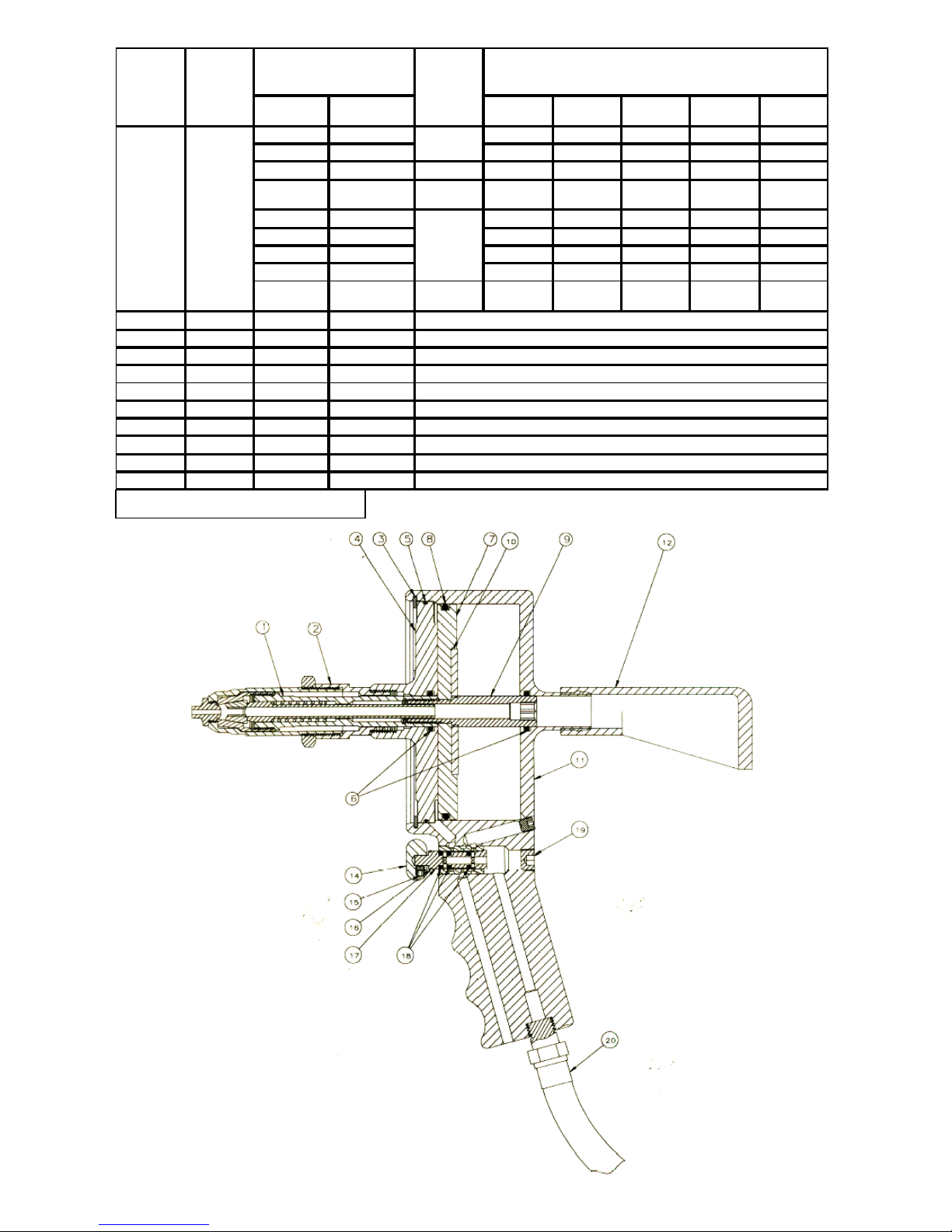
REF. NO.
1
4
11
5
2
3
6
8
7
9
10
* MUST BE ORDERED SEPARATELY.
QTY.
REQ .
1
1
1
1
1
SET
1
2
1
1
1
1
PART NUMBER FOR TWO
PULLING HEAD S —
H703 *H743A
*728A9-3Z— ALL————
728A9-4
628A9-4 —
*728A9-104 — 5/32
728A9-4 — — — ALL — —
728A9-6 *743A7-5C6Z AAP, BSP AAP — — —
— *743B35 — — — BAPV —
—*743C53 ————ALL
728A9-6 *743A7-5C6Z
703B7 *743B91
743A18 *743A18
703A8 *743B92
72 8B 4 (2 PC) * 7 43 C5 5 (3 PC )
743A8-8Z *743B93
— *P-1195
— *743A95
— *743B94
732A8 *732A8
— *743A14-8Z
————
RIVET
DI AM.
3/32
1/8
3/16
1/4 — —
SLEEVE
JAM NUT
COLLET
JAWS
JAW FOLLOWER
0-RIN G
CUSHION
SPRI NG FOLLOWER
JAW SPRING
EJECT OR TUBE
N
RI VE T
ALLALL———
AAP,BSP,
SSP
COMMERCIAL FASTENER TYPE
Q
RIVET
AAA,BSP,
SSP
CherryMate
RIVET
———
BALM,
BSLM
Monobolt
RIVET
Kl amp Tite
RI VE T
——
6
Page 7
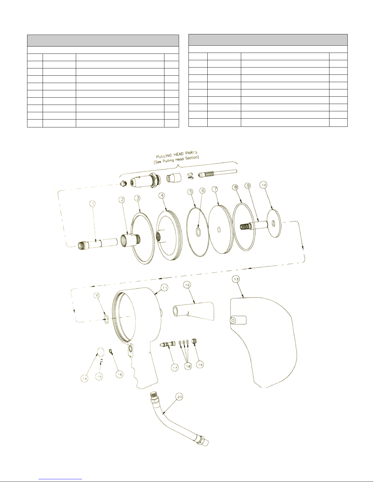
PARTS LIST FOR THE GH-780 POWER RIVETER
ITEM PART
NO. NO. DESCRIPTION QTY
780C1 Sub-Assembly, Riveter
1 670B31 Rod, Piston 1
2 670B32 Sleeve 1
3 P-1290 Ring, Retaining 1
4 670B2 Plate, Nose 1
5
P-507 O-Ring (3.879, 3.739, .070)
6
P-508 O-Ring (.755, .549, .103)
7 670B3 Piston 1
8 P-534 O-Ring (4.012, 3.734, .139) 1
9 670A33 Drawbolt 1
10 670A21 Cushion 1
*Furnished only on special order
1
2
13 *670A20 Mandrel Catcher Bag
14 670A7 Trigger
15 P-510 Screw, Soc Hd Set, 8-32 x 3/16
16 P-295 Ring, Retaining
17 620A79 Spool, Valve 1
18 P-293 O-Ring (.316, .176, .070) 3
19 P-698 Plug, Pipe
20 *P-948 Hose 1
EXPLODED VIEW OF GH-780
ITEM PART
NO. NO. DESCRIPTION QTY
780C1 Sub-Assembly, Riveter
11 670C4 Housing 1
12 530A16 Deflector 1
1
1
1
1
1
7
Page 8
,
®
WARRANTY
Seller warrants the goods conform to applicable specifications and drawings and will be manufactured and inspected according to generally accepted practices of
companies manufacturing industrial or aerospace fasteners. In the event of any breach of the foregoing warranty, Buyer’s sole remedy shall be to return defective
goods (after receiving authorization from Seller) for replacement or refund of the purchase price, at the Seller’s option. Seller agrees to any freight costs in
connection with the return of any defective goods, but any costs relating to removal of the defective or nonconforming goods or installation of replacement goods
shall be Buyer’s responsibility. SELLER’S WARRANTY DOES NOT APPLY WHEN ANY PHYSICAL OR CHEMICAL CHANGE IN THE FORM OF THE
PRODUCT IS MADE BY BUYER.
THE FOREGOING EXPRESS WARRANTY AND REMEDY ARE EXCLUSIVE AND ARE IN LIEU OF ALL OTHER WAR RANTIES AND REMEDIES;
ANY IMPLIED WARRANTY AS TO QUALITY, FITNESS FOR PURPOSE, OR MERCHANTABILITY IS HEREBY SPECIFICALLY DISCLAIMED AND
EXCLUDED BY SELLER.
(1) YEAR AFTER INITIAL USE BY BUYER OF ANY POWER RIVETER OR NINETY (90) DAYS AFTER INITIAL USE OF ANY OTHER PRODUCT.
Seller shall not be liable under any circumstances for incidental, special or consequential damages arising in whole or in part from any breach by Seller, AND SUCH
INCIDENTAL
SPECIAL, OR CONSEQUENTIAL DAMAGES ARE HEREBY EXPRESSLY EXCLUDED.
THIS WARRANTY IS VOID IF SELLER IS NOT NOTIFIED IN WRITING OF ANY REJECTION OF THE GOODS WITHIN ONE
For more information please contact our Technical Services Department at Tel. 714-850-6022
LOCTITE
is a registered trademark of Henkel Corporation
®
is a registered trademark of GM corporation.
DEXRON
PARKER® is a trademark of Parker Hannifin Corporation
LUBRRIPLATE
®
is a trademark of Fiske Brothers Refining Co.
© 2008 Cherry Aerospace Supplier’s Federal Identification Code: 11815 TM-GH-780
Rev.: B
Date: 20 Nov 08
DCR# 08-1560
1224 East Warner Ave,
Santa Ana, CA 92705
Tel: 1-714-545-5511
Fax: 1-714-850-6093
www.cherryaerospace.com
 Loading...