

Page 1
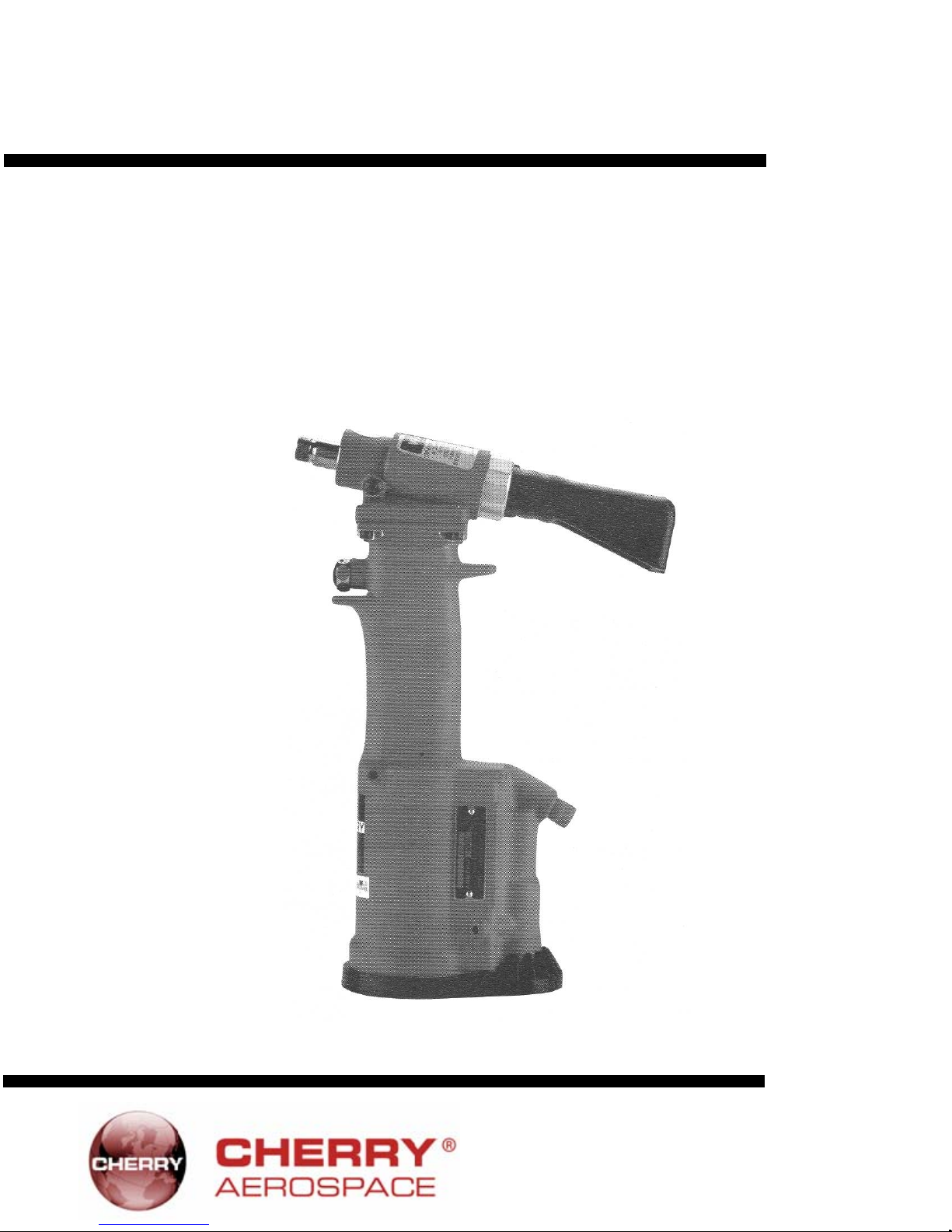
GH-702A
Lightweight Power Tool
MAINTENANCE MANUAL
1224 East Warner Ave,
Santa Ana, Ca 92705
Tel: 1-714-545-5511
Fax: 1-714-850-6093
www.cherryaerospace.com
Page 2
A
A
r
r
r
THE GH-702A TOOL
TABLE OF CONTENTS
Description ...........................................................................................................................................1
Specifications For GH-702A ...................................................................................................................................................1
Safety Warnings ......................................................................................................................................................................2
How To Use The GH-702A .................................................................................................................3
Maintenance And Repair ........................................................................................................................................................ 3
Fill And Bleed Instructions ...................................................................................................................4
Trouble Shooting .................................................................................................................................4
Overhaul ...............................................................................................................................................5
Air Valve .....................................................................................................................................................................5
Head Sub-Assembly ..................................................................................................................................................5
Handle Sub-Assembly ...............................................................................................................................................6
Pulling Heads .......................................................................................................................................6
Installing Pulling Heads .............................................................................................................................................7
Cross Section Drawing Of GH-702A ...................................................................................................................................... 8
Parts List For GH-702A Riveter ..........................................................................................................9
Exploded View Of GH-702A .................................................................................................................................................10
Declaration Of Conformity ......................................................................................................................................Back Cover
DESCRIPTION
The Cherry GH-702A is a pneumatic-hydraulic tool designed
specifically for the most efficient installation of
commercial fasteners. Its durable, all metal housing makes
this extremely robust tool ideal for use in rugged shop
environments. It has many ergonomic features: very light
weight, comfortable fit in the operator's hand and it can be
operated in any position with one hand.
SPECIFICATIONS FOR GH-702A
Cherry Aerospace's policy is one of continuous
development. Specifications shown in this document
may be subject to change which may be introduced
after publication. For the latest information always
consult Cherry Aerospace.
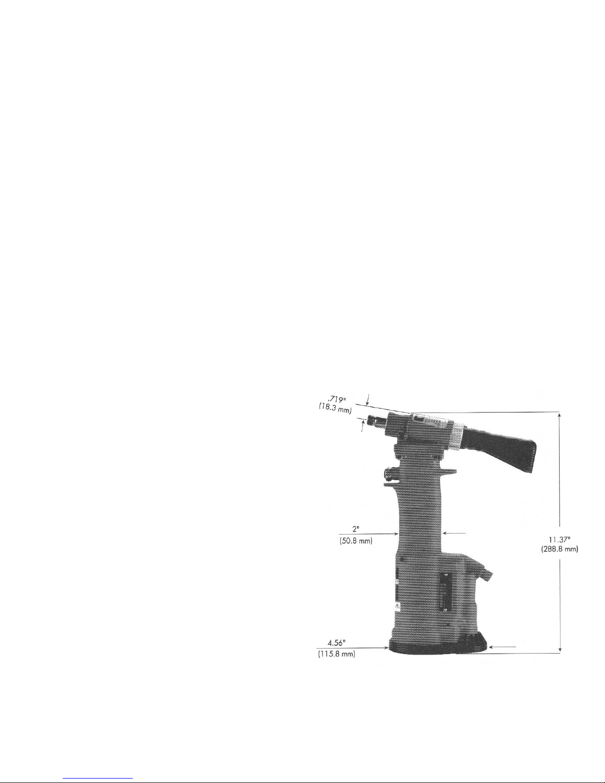
IR PRESSURE 90 PSI (6.2 bar) Min. / 110 PSI (7.6 bar) Max.
STROKE .75 inch (19 mm)
PULLING FORCE 1100 Pounds (4.9 kN) @ 90 PSI (6.2 bar)
CYCLE TIME Approximately One Second
WEIGHT 3.5 Pounds (1.59 kg)
NOISE LEVEL 65 dB (A)
VIBRATION less than 2.5 m/s2
IR CONSUMPTION .066 SCF/cycle (1.87 L/cycle)
The GH-702A comes equipped with
nosepiece 728A9-4, included for
setting:
N Rivets - 1 /8” diameter
Q Rivets - 1 /8” diameter
Cherrymate® Rivets- 3/16” diameter
There is also a spare nosepiece
728A9-6 to set:
N Rivets - 3/16” diamete
Q Rivets - 3/16” diamete
Cherrymate® Rivets - 1 /4” diamete
1
Page 3

SAFETY WARNINGS
Operating this tool with a damaged or missing stem deflector, or using the deflector as a handle, may
result in severe personal injury. The pin d ef l ec t or should be ro t a te d u nt i l the a p er t ur e i s f ac i n g a w ay
from the operator and other persons working in the vicinity.
Approved eye protection should be worn when operating, repairing, or overhauling this tool.
Do not use beyond the design intent.
Do not use substitute components for repair.
Any modification to the tool, pulling heads, accessories or any component supplied by Cherry Aerospace,
or their representatives, shall be the customer's entire responsibility. Cherry Aerospace will be pleased
to advise on any proposed modification.
The tool must be maintained in a safe working condition at all times and examined at regular intervals for
damage.
Before disassembling the tool for repair, refer to the maintenance instructions. All repairs shall be
undertaken only by personnel trained in Cherry Aerospace installation tools. Contact Cherry Aerospace
with your training requirement.
Always disconnect the air line from the tool inlet before attempting to service, adjust, fit or remove any
accessory.
Do not operate the tool when it is directed at any person.
Ensure that the vent holes do not become blocked or covered and that air line hoses are always in good
condition.
Excessive contact with the hydraulic oil sho uld be a vo id ed to mi ni mi ze the possibility of rashes. Care should be taken to
wash thoroughly.
Operating air pressure should not exceed 110 psi (7.6 bar).
Do not operate the tool without the pulling head in place.
Do not operate the tool unless the handle base (25) is fully secured by the retaining rings (26) and (28) and
base cover (27).
All retaining rings, screwed end caps, air fittings, trigger valves and pulling heads should be attached
securely and examined at the end of each working shift.
Do not pull rivet in the air.
The precautions to be used when using this tool must be explained by the customer to all operators. Any questions regarding
the correct operation of the tool and operator safety should be directed to Cherry Aerospace.
Do not pound on the rear of the tool head to force rivets into holes as this will damage the tool.
Do not depress the trigger while disconnecting the air bleeder and replacing the cap screw when bleeding the tool.
2
Page 4
HOW TO USE THE GH-702A
After selecting the proper pulling head and attaching it securely to the GH-702A, conn ect the air line to the tool. Insert the rivet
stem into the pulling head until the head of the rivet is in contact with the pulling head sleeve. This will ensure full engag ement
between the jaws and the rivet stem and will prevent slippage.
Once the rivet stem is inserted in the pulling head, the rivet must be installed. Insert the rivet into the application and pull the
trigger to activate the tool. Upon the release of the trigger, the stem will eject to the rear of the tool.
MAINTENANCE AND REPAIR
The GH-702A has been manufactured to give maximum service with minimum care. In order that this may be accomplished, the
following recommendations should be followed:
1. The hydraulic system should be full of oil and free from air at all times.
2. Keep excessive moisture and dirt out of air supply to prevent wear of air valve, air cylinder and air piston.
3. Tool should be routinely inspected for oil leaks.
Use automatic transmission fluid Type "A" (no substitutes). Cherry Aerospace recommends using ATF, Dexron III oil.
DEXRON III OIL SAFETY DATA
FIRST AID
Skin: Wash thoroughly with soap and water as soon as possible. Casual contact requires no immediate attention. If
irritation develops, consult a physician.
Ingestion: Seek medical attention immediately. DO NOT INDUCE VOMITING.
Eyes: Flush with copious amounts of water. If irritation develops, consult a physician.
Inhalation: No significant adverse health effects are expected to occur on short term exposure. Remove from contaminated area.
FIRE
Suitable extinguishing media: CO2, dry powder, foam or water fog. DO NOT use water jets.
ENVIRONMENT
Waste Disposal: In accordance with local, state and federal regulations.
Spillage: Prevent entry into drains, sewers and water courses. Soak up with diatomaceous earth or other inert material. Store in
HANDLING
Eye protection required. Protective gloves recommended. Chemically resistant boots and apron recommended. Use in well ventilated area.
COMBUSTIBILITY
Slightly combustible when heated above flash point. Will release flammable vapor which can burn in open or be explosive in
confined spaces if exposed to source of ignition.
Apply artificial respiration if needed. If unconscious, consult physician.
appropriate container for disposal.
STORAGE
Avoid storage near open flame or other sources of ignition.
PROPERTIES
Specific gravity 0.863
Weight per gallon 7.18 lbs.
3
Page 5
FILL AND BLEED INSTRUCTIONS
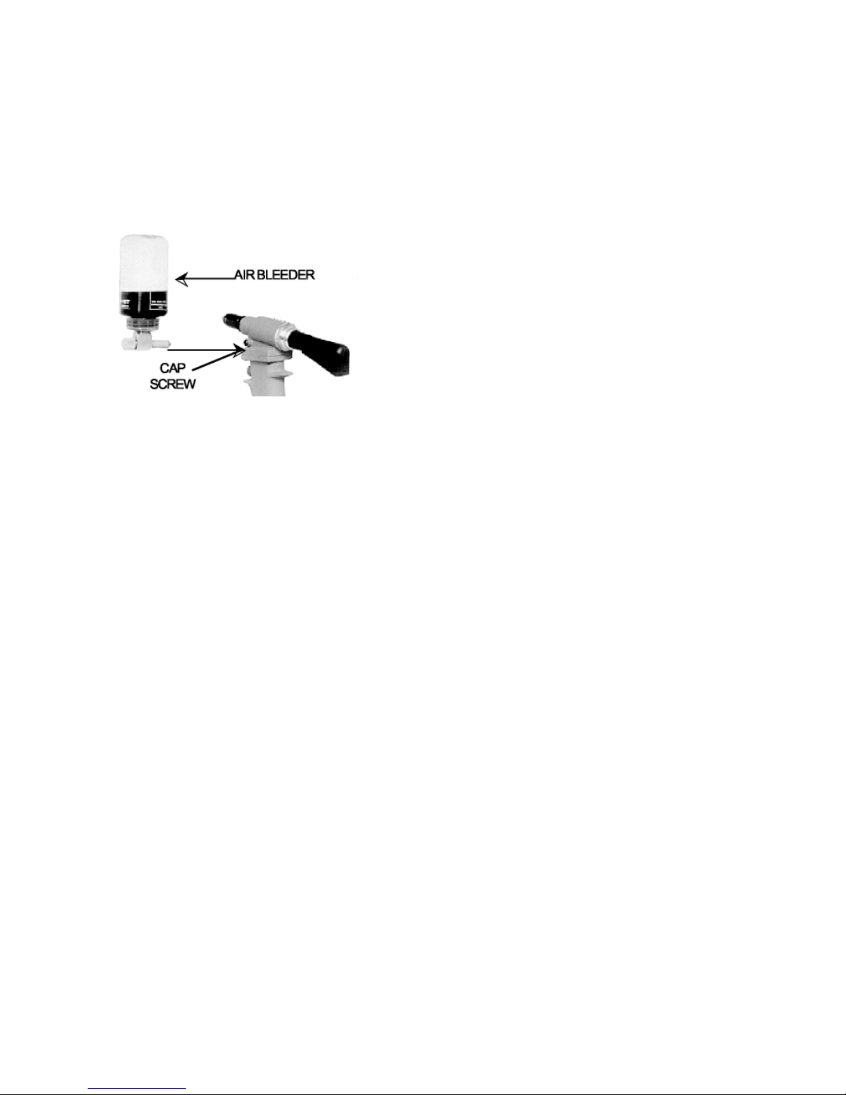
To replace a small amount of oil in the tool, remove cap screw (15), attach the Cherry air bleeder (700A77), connect the tool to the
air line and cycle several times. This will ensure the removal of any air from the h ydraulic system and its replacement with fluid.
Should it become necessary to completely refill the tool (such as would be required after the tool has been dismantled and reassembled), take the following steps:
1. Remove head assembly (1) from handle (32) by
unscrewing cap screws (50).
2. Fill handle assembly (32) with the recommended oil to
within 1/8" (3.175mm) of the top of the handle casting.
3. Place head assembly (1) on handle (32), being sure
gasket (49), and 0-ring (48), are properly in place.
Tighten cap screws (50) uniformly to prevent leakage
around gasket.
(15)
TROUBLESHOOTING
1. Check the air line for correct pressure at the tool. It
must be 90 to 110 psi (6.2 to 7.6 bar).
2. Check the tool for lack of oil (see Fill and Bleed
instructions).
3. Check for oil leakage:
Oil leaking around the cap screw (15) in the head
indicates that the screw is loose or the Stat-O-Seal
(14) needs replacing.
If oil should leak through the by-pass hole at the
base of
the handle (32) the 0-rings (34) are worn or
damaged.
Oil leaking from the front of the head (1) indicates
that 0-rings (2) are worn or damaged.
4. Remove cap screw (15) and attach the Cherry air
bleeder (700A77). Connect the tool to the air line and
cycle a number of times. This will ensure the removal of
any air from its hydraulic system and its replacement
with fluid.
5. Check movement of the head piston (4). If it does not
move freely or is slow in operation:
0-rings (2), (5), (7) and (8) may be damaged and
require replacement.
Head piston (4) may be mechanically locked
due to damaged parts.
The 0-ring (36) on power piston rod (37)
may be damaged; replace.
Muffler (46) or air filter (42) inside valve spool (41)
may be plugged with dirt. Clean them thoroughly
with normal solvent and back-blow with compressed
air.
Hole in metering screw (43) in valve spool (41)
may be blocked or damaged. Hole diameter should
be .028" (.711 mm). Clear and size or replace
valve spool assembly (40).
4. Check for excessive air leakage from the air valve:
If spring (39) is broken or dislodg ed, air will
bleed directly through the bottom of the air valve
and the head piston retrea ts to i t s full str o k e
without returning. See air valve instructions on
page 5.
If 0-ring (44) on plug (45) is worn or damaged,
replace.
If 0-rings (36) on valve spool (41) are worn
or damaged, replace.
6. Rivet stem sticks in the pulling head:
Pulling head components need maintenance.
Disassemble the pulling head, clean and replace
worn parts. Re-assemble following instructions on
page 7.
Spent rivet stems are wedged side by side in the
pulling head. Disassemble the pulling head, remove
stems and re-assemble following the instructions on
page 7.
4
Page 6
l
700477
700A460
700A
61
P
1178
A
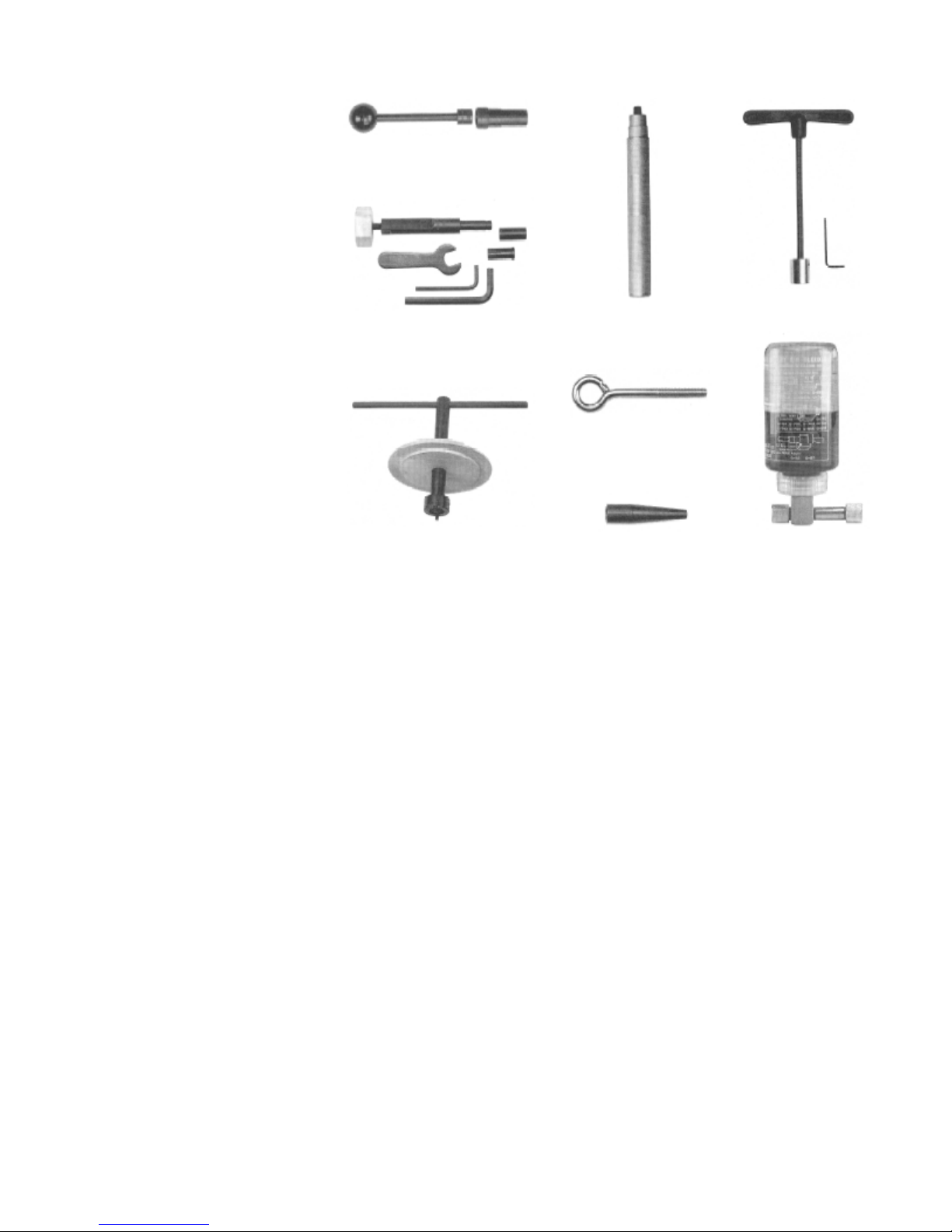
OVERHAUL THE G701/G704KT TOOL KIT
The disassembly and re-assembly procedures can be accomplished by following
the instructions below and the drawings on
pages 8 & 10. Use extreme care during
disassembly and re-assembly not
to mar, nick or burr any smooth
surface that co mes in co ntact wi th
0-rings. Before installing 0-rings, be
sure to apply an 0-ring lubricant. It is
recommended that special assembly
too ls , w hi ch ca n be ordered under part
number G7O1/G7O4KT, be used to
overhaul this tool. Service kit, G7O2AKS,
which contains a complete set of 0-rings,
back-up rings, screws, washers and
gaskets should be ordered.
Valve Spring Installation Tool
Valve Sleeve Removal Tool
836B700
8375700
62
700
Power Cylinder Tool
Piston Rod Wrench
Not shown, but included: 701A67 Sea
Guide, 702862 Power Cylinder Tool,
703A53 Seal Guide, 702A64 Seal Guide.
Valve Plug Extractor
700B65
Packing Plug Wrench
Seal Guide
Air Bleeder
AIR VALVE
Remove retaining ring (47) and muffler (46). Insert a valve plug extractor (P1178) into end of valve plug (45) and pull it out.
Using the same procedures, pull out valve spool sub-assembly (40).
Use needle nose pliers to grasp the end of the spring (39), turn clockwise and pull out to dislodg e from groove in handle.
With spring removed, valve sleeve (38) can be pulled out using the valve sleeve remova l tool (837B700).
To re-assemble, reverse the above proce dures, being certain that all 0-rings are proper ly lubricated. To avoid damag ing the
0-rings (2), carefully install sleeve (38) with your finger. Gently push and wiggle sleeve to allow 0-rings to slip past inner ports.
Spring (39) is best installed using a valve spring installation tool (836B7 00) to push the large diameter coil into the groove. This
requires care as the tool will not operate if the spring is not anchored firmly.
HEAD SUB-ASSEMBLY
Disconnect the air supply and remove the complete pulling head from the tool before attempting to disassemble the
head assembly.
Remove the four socket head cap screws (50). Lift head assembly from the handle (32). Remove 0-ring (48) and gasket
(49). Empty the oil into a container by pouring from the handle. Dispose of the oil according to environmental regulations.
Remove end cap (10). Push against threaded end of head piston (4) and slide it out of head cylinder (1). Be careful no t to
damage threads or cause burrs on polished head piston rod surface.
0-rings (2) and back-up ring (3) can now be removed using a bent hook. 0-ring (8) can be removed in the same manner.
Upon re-assembly, be sure to install 0-rings and back-up rings carefully to avoid cutting them. Always lubricate all 0-rings.
Just prior to placing the head sub-assembly onto the handle, see Fill and Bleed Instructions. Also make sure to place 0-rin g
(48) on top of the handle in its groove, and then the gasket (49) over the 0-ring (48).
Tighten the four socket head cap screws (50) uniformly to prevent leakage around the ga sket.
Purge system of air using Cherry air bleeder (700A77) according to Fill & Bleed Instructions.
5
Page 7

HANDLE SUB-ASSEMBLY
Disconnect tool from air supply and remove parts (25) through (29).
Remove the head sub-assembly using the instructions in the head sub-assembl y section.
Place piston rod wrench (700A61) down into the top of the handle (32), into the hex socket in the head of the power piston
rod (37). While holding this wrench, remove the locknut (24) using the 7/16" socket in packing plug wrench (700B65).
Still holding the piston rod wrench, remove the air piston (22) using the packing plug wrench (700B65) by turning
counterclockwise. When air piston (22) is completely freed from the piston rod, tap or push on the piston rod wrench to eject
the piston from bottom of handle.
Slide power piston rod (37) back up to the end of its travel. Using the packing plug wrench (700B65), remove
packing plug (19). It may be necessary to hold the handle upside down in a vise while removing the packing p lug.
Power cylinder (33) can be tapped out by lowering power cylinder tool (700A62) down into the top of the handle on to top of
cylinder. The 0-rings (16) and backup rings (17) are best removed and replaced by using a thin bent hook.
To re-assemble the handle, reverse the above procedure, being certain that all the 0-rings are properly lubricated before installation. Attach the seal guide (700A60) to the piston rod (37) and with a mallet, tap the piston rod through the packing plug (19).
When re-assembling a replacement air piston, items (20) through (23), follow the instructions given below:
Clamp piston rod wrench (700A61) in a vise with the hex shaft pointed up.
Turn the handle upside down and place the hex end of the power piston rod (37) onto the wrench. Push handle casting down
until it stops.
Assemble 0-ring (20) to air piston (22).
Place large washer (21) over the threaded end of the power piston rod (37).
Place the air piston (22) into handle bore. IMPORTANT: Be sure that the radial pattern embossed on the side of air piston
is facing downward towards the large washer (21) and the smooth side of the air piston is facing you.
Place the small washer (23) over the threaded end of the power piston rod (37). Thread the locknut (24) onto the power
piston rod (37) and tighten between 50 in.-lb (5.65 N-m) and 59 in.-lb (6.67 N-m).
6
Page 8
—
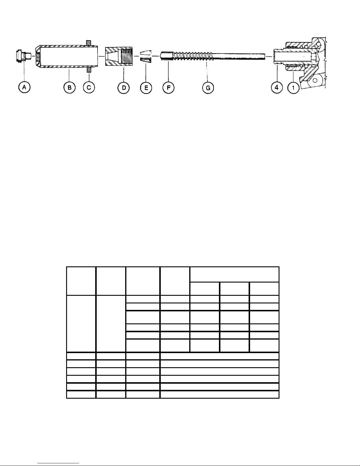
INSTALLING H702 PULLING HEAD ON RIVETER
1. Connect tool to air supply and without
depressing trigger, place spring (G) over
tube (F) as shown and insert as far as
possible into head piston (4).
2. Place jaws (E) inside collet (D) and screw
this assembly onto end of head piston (4).
Tighten snugly, using wrenches on the flats
provided. NOTE: Make sure tapered end of
tube (F) is aligned properly in bevel in back
end of jaws (E).
3. Thread nose piece (A) completely into
sleeve (B) and place this assembly over the
collet and jaw assembly. Screw sleeve (B)
into end of tool head (1) while depressing
trigger and tighten snugly.
REF. NO.
A
B
C
D
E
F
G
QTY.
REQ.
SEE CHART
AT RIGHT
1
1
1
SET
1
1
1
PART
NUMBER
728A9-3 Z
728A9-4
72 8A9-104 5/32
728A9-4
728A9-6 AAP, BSP AAP —
728A9-6 1/4 — —
702B19
671A16
702A20
728B4
743A8-8 Z
732A8
4. Tighten jam nut (C) securely.
5. These pulling heads will give long life if
properly maintained. This includes keeping
the head clean and dry and all the parts
securely tightened. The only lubrication
required is a little Lubriplate inside the cone
of the collet to assure a sliding action
against the back of the jaws.
6. In case of damage or wear to pulling head
parts, dismantle and replace with parts
selected from the list below.
RI VET
DIAM.
3/32
1/8
AAP,BSP,
3/16
SLEEVE
JAM NUT
COLLET
JAWS (2 PIECE)
JAW FOLLOWER
JAW SPRING
COMMERCIAL FASTE NER TYPE
N
RI VET
ALL
ALL ALL —
SSP
——ALL
Q
RIV ET
AAA,BSP,
SSP
CherryMate
RIVE T
—
—
BALM,
BSLM
7
Page 9
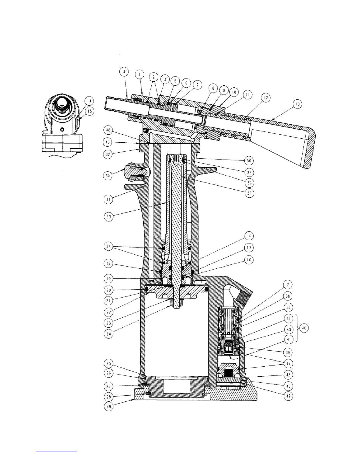
CROSS SECTION OF GH-702A
8
Page 10
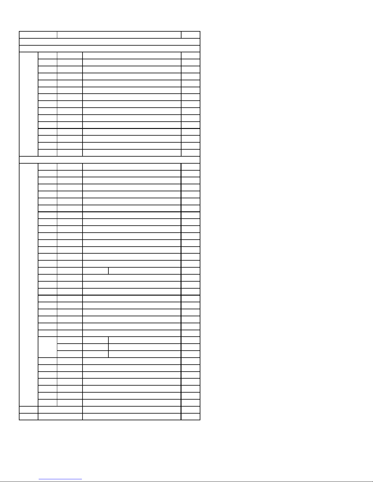
PART LIST FOR THE GH-702A RIVETER ASSEMBLY
PART NO. DESCRIPTION
702-054 (G702A RIVER ASSEMBLY)
702B15 SUB-ASSEMBLY, HEAD
1
702C2 SUB -ASSEMBLY, HEAD CYCLINDER
26
P-653 O-RING (.691, .551, .070)
31
P-883 RING, BACK-UP (.686, .580, .053)
41
702B16 PISTON, HEAD
51
P-216 RING, QUAD (.880, .674, .103)
61
P-209 RING, BACK-UP (.864, .688, .088)
71
P-654 O-RING (.879, .739, .070)
81
P-112 0-RING (.504, .364, .070)
91
P-848 O-RING (.941, .801..070)
10 1
702B17 CAP
11 1
P-880 RING, RETAINING (NON-STANDARD)
12 1
703A13 FITTING, DEFLECTOR
13 1
530A16 DEFLECTOR, PIN
14 1
P-572 STAT-O-SEAL (.430,
15 1
P-573 SCREW, BUTTON HEAD SOC., 10-32 X 1/4
702-053 SUB-ASSEMBLY, HANDLE
16 2
P-838 O-RING (.568, .362_1 03)**
17 2
P-115 RING, BACK-UP (.551, .375, .088)
18 1
P-727 O-RING (1.318, 1.112, .103)
19 1
700B93 PLUG, PACKING
20 1
P-893 O-RING (2.387, 2.109, .139)
21 1
700A21 WASHER
22 1
747-013 PISTON, AIR
23 1
P-1387 WASHER, STEEL
24 1
P-737 NUT, CONEL K, 1/4-20
25 1
747-015 BASE, HANDLE
26 1
P-894 O-RING (2.254, 2.114, .070)
27 1
P-895 RING, RETAINING (INT. Ø 2.440)
28 1
P-1386 RING, RETAINING (EXT. Ø 2.062)
29 1
747-011 COVER, URETHANE BASE
30 1
703A33 SUB-ASSEMBLY, TRIGGER
31 P-223 O-RING (.285, .145, .070) 1
32 1
747-018 HANDLE
33 1
747-019 CYLINDER, POWER
34 2
P-833 O-RING, DISOGRIN (1.068, .862, .103)
35 1
P-919 RING, BACK-UP (.528, .422, .053)
36 4
P-829 O-RING, DISOGRIN (.504, .364, .070)**
37 1
747-017 PISTON, POWER
38 1
700B73 SLEEVE, VALVE
39 1
700A67 SPRING
40 1
700A15 SUB-ASSEMBLY, VALVE SPOOL
41
700D15-2
42
700A18
43
700A69
44 2
P-834 O-RING (.816 .676, .070)**
45 1
700A16 PLUG, VALVE
46 1
700A17 MUFFLER
47 1
P-279 RING, RETAINING (INT. Ø .906)
48 1
P-832 O-RING (.379, .239, .070)**
51
52
49 1
702A22
50 4
P-27 SCREW, SOC. HD. CAP, 8/32 X 1/2
670-037-1
P-948
GASKET
ASSEMBLY, MANDREL CATCHER BAG*
HOSE
.180, .125)
SPOOL, VALVE***
FILTER***
SCREW, METERING***
"Not furnished with riveter. Must be ordered separately if desired.
**No substitutions.
***These parts can not be ordered separately, but must be ordered as a sub-assembly.
All dimensions are in inches.
QTY.
1
1
1
1
1
1
9
Page 11
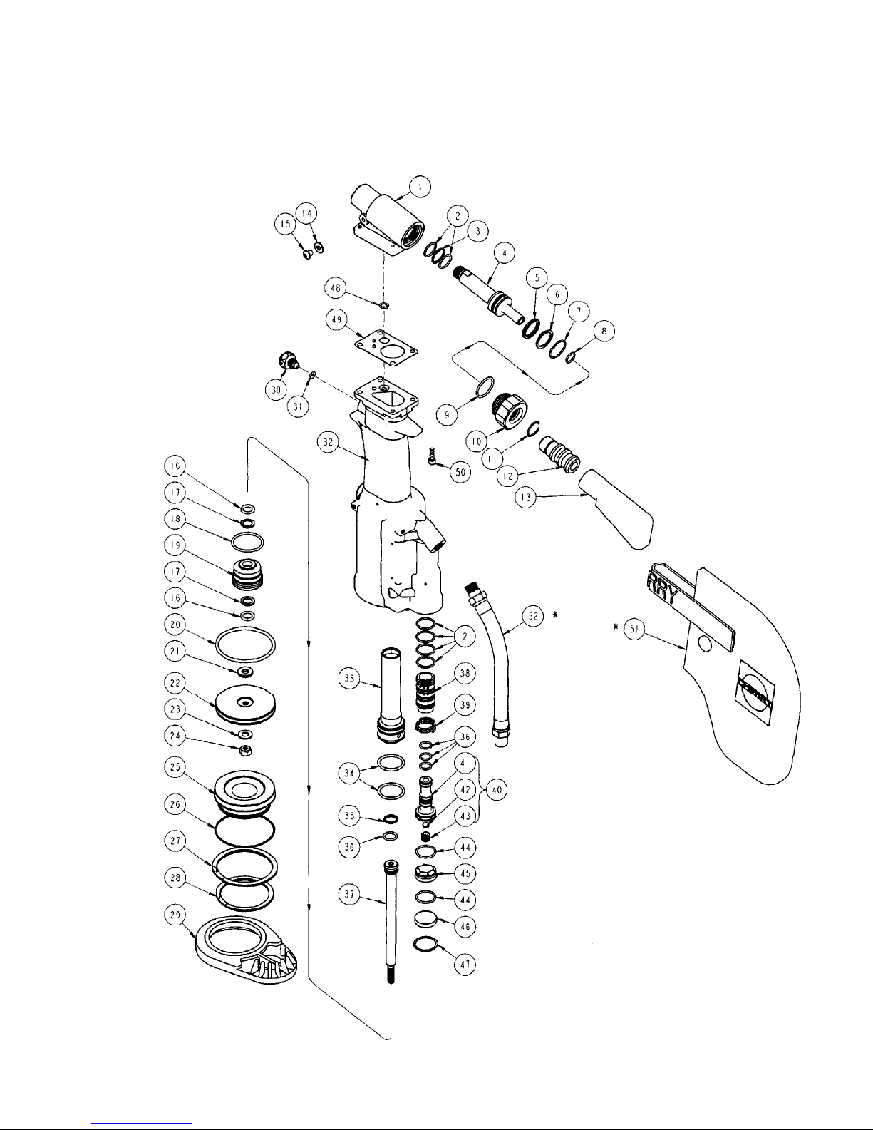
EXPLODED VIEW OF GH-702A
10
Page 12
,
®
WARRANTY
Seller warrants the goods conform to applicable specifications and drawings and will be manufactured and inspected according to generally accepted practices of
companies manufacturing industrial or aerospace fasteners. In the event of any breach of the foregoing warranty, Buyer’s sole remedy shall be to return defective
goods (after receiving authorization from Seller) for replacement or refund of the purchase price, at the Seller’s option. Seller agrees to any freight costs in
connection with the return of any defective goods, but any costs relating to removal of the defective or nonconforming goods or installation of replacement goods
shall be Buyer’s responsibility. SELLER’S WARRANTY DOES NOT APPLY WHEN ANY PHYSICAL OR CHEMICAL CHANGE IN THE FORM OF THE
PRODUCT IS MADE BY BUYER.
THE FOREGOING EXPRESS WARRANTY AND REMEDY ARE EXCLUSIVE AND ARE IN LIEU OF ALL OTHER WAR RANTIES AND REMEDIES;
ANY IMPLIED WARRANTY AS TO QUALITY, FITNESS FOR PURPOSE, OR MERCHANTABILITY IS HEREBY SPECIFICALLY DISCLAIMED AND
EXCLUDED BY SELLER.
THIS WARRANTY IS VOID IF SELLER IS NOT NOTIFIED IN WRITING OF ANY REJECTION OF THE GOODS WITHIN ONE
(1) YEAR AFTER INITIAL USE BY BUYER OF ANY POWER RIVETER OR NINETY (90) DAYS AFTER INITIAL USE OF ANY OTHER PRODUCT.
Seller shall not be liable under any circumstances for incidental, special or consequential damages arising in whole or in part from any breach by Seller, AND SUCH
INCIDENTAL
SPECIAL, OR CONSEQUENTIAL DAMAGES ARE HEREBY EXPRESSLY EXCLUDED.
For more information please contact our Technical Services Department at Tel. 714-850-6022
LOCTITE
DEXRON
PARKER
LUBRRIPLATE
is a registered trademark of Henkel Corporation
®
is a registered trademark of GM corporation.
®
is a trademark of Parker Hannifin Corporation
®
is a trademark of Fiske Brothers Refining Co.
1224 East Warner Ave,
Santa Ana, Ca 92705
Tel: 1-714-545-5511
Fax: 1-714-850-6093
www.cherryaerospace.com
© 2010 Cherry Aerospace Supplier’s Federal Identification Code: 11815 TM-GH-702A
Rev.: C
Date: 9-01-10
CR# 10-0990
11
 Loading...