

Bedienungsanleitung
User Manual
Manuel d’utilisation
Fingerprint G 81-12000/12100
Gedruckt auf Recycling-Papier.
II
Deutsch
English
Français
Table of Contents
englisch____________________________________________________________________8
Table de matières
französisch ________________________________________________________________14
Inhaltsverzeichnis
Seite
Bildbeschreibung ______________________________________________________________________2
Gültigkeitsnachweis____________________________________________________________________2
1.Allgemeiner Anwenderhinweis ________________________________________________________3
2.Einführung __________________________________________________________________________3
2.1 Allgemeine Tastatur-Beschreibung __________________________________________________3
2.2 Fingerprint-Modul_________________________________________________________________3
2.3 Smartcard-Leseeinheit ____________________________________________________________4
2.4 Modell Core Plus _________________________________________________________________4
2.5 Modell Single Core FPR ___________________________________________________________4
3.Installation __________________________________________________________________________4
3.1 Systemanforderungen ____________________________________________________________4
3.2 Software ________________________________________________________________________5
3.3 Installation des Smartcard Lesers __________________________________________________5
3.3.1 G 81-12000LTB... ______________________________________________________5
3.3.2 G 81-12000LTC.../LVD __________________________________________________5
4.Gebrauch des integriertem Smartcard Terminals _________________________________________5
4.1 Einlegen der Smartcard ___________________________________________________________5
4.2 Einlegen der Plug In Karte _________________________________________________________5
5.Firmware ___________________________________________________________________________6
6.Statusanzeigen ______________________________________________________________________6
6.1 Modell Single Core-FPR ________________________________________________6
7.Technische Daten ___________________________________________________________________6
7.1 Technische Daten der Tastatur _____________________________________________________6
8.Fehlerbeseitigung ___________________________________________________________________7
9.Zubehör ____________________________________________________________________________7
japanisch__________________________________________________________________21
chinesisch ________________________________________________________________30
➁
➆
➈
III
LOCK
LOCK
LOCK
1
2
4
3
➀
➃
➄
➅
➂
➇
➉
➂
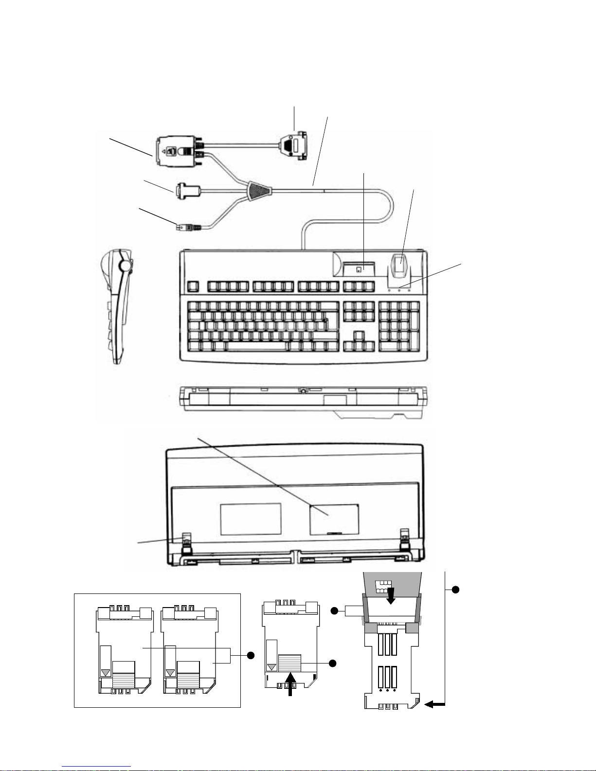
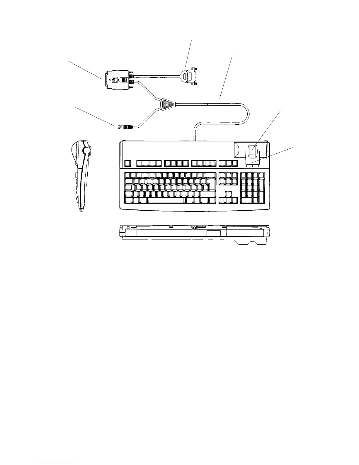
Bildbeschreibung
➭Zeichnung Seite III
Tastatur Modellreihe 12000/12100
➀ Chipkartenschacht senkrecht
➁ Fingerprintmodul
➂ Leuchtdioden für die Statusanzeigen
➃ Tastatur-Anschlußkabel
➄ Plug-In-Abdeckung
➅ Verstellbare Füße
➆ 25poliger SUB-D Stecker für
Fingerprintmodul
➇ 9poliger SUB-D Stecker
➈ Tastatur-Stecker PS/2
➉ Pass through-Stecker (optional)
Plug ins
➊ Plug-In Gehäuse
➋ Verriegelung
2
➌ Abgeschrägte Kanten
➍ Führungsschiene
Dateneingabegeräte von Cherry zeichnen
sich durch hohe Qualität und Zuverlässigkeit aus. Entwickelt vor allem für
professionelle Schreibanwendungen
entsprechen Cherry Tastaturen sämtliche
richtungsweisenden Maßgaben des
Marktes und Ergonomie. Sie bieten
ausgereifte und innovative Technik mit
hohem Komfort für erfolgreiche Anwendungen in der Büro- und Datentechnik.
Gültigkeit dieser
Bedienungsanleitung
Diese Bedienungsanleitung ist gültig
für alle Tastaturen der Modellreihen
12000/12100.
➁
➃
➉
➆
➈

1. Allgemeiner
Anwenderhinweis
Cherry optimiert seine Produkte ständig
im Zuge der Entwicklung von neuen
Technologien. Technische Änderungen
behalten wir uns deshalb vor. Die
Ermittlung der Zuverlässigkeit sowie die
Definition von technischen Angaben
erfolgt gemäß Cherry-interner Prüfung,
um international anerkannte Vorschriften
bzw. Normen zu erfüllen. Davon abweichende Anforderungen können durch
gegenseitige Zusammenarbeit erfüllt
werden. Unsachgemäße Behandlung,
Lagerung und äußere Einflüsse können
zu Störungen und Schäden im Einsatz
führen. Wir übernehmen keinerlei
Gewährleistung, falls unser Produkt
anwenderseitig verändert wird und
haften nicht im Falle unbefugter Veränderungen. Alle Reparaturen müssen
durch Cherry oder eine offiziell
berechtigte Person oder Organisation
durchgeführt werden. Bei unsachgemäßem Austausch der optional
eingesetzten Lithiumbatterie besteht
Explosionsgefahr! Etwaige Schadensersatzansprüche gegen Cherry oder seine
eingesetzten Vertreter – gleich aus
welchem Rechtsgrund (einschließlich
streßbedingte körperliche Schäden) sind
ausgeschlossen, soweit uns nicht
Vorsatz oder Nichtbeachtung gültiger
Produkthaftungsbestimmungen trifft. Die
vorliegende Bedienungsanleitung ist nur
gültig für die mitgelieferte Tastatur.
Weitere Informationen darüber sind bei
den jeweiligen Cherry Distributoren oder
direkt über die Cherry GmbH erhältlich.
Aktuellste Informationen stehen
im Internet ständig zur Verfügung
unter: http://www.cherry.de
3
2. Einführung
2.1 Allgemeine TastaturBeschreibung
Die Tastaturen der Cherry Modellreihe
G 81-12000/12100, Einzelmodelle
FPR 12000/FPR 12100, Core Plus-FPR
und Single Core-FPR gehören zu einer
neuen Generation der BiometricTastaturen auch mit integriertem Smart
Card Leser.
2.2 Fingerprint-Modul
Das integrierte Fingerprint-Modul ermöglicht das Einlesen von Fingerabdrücken
des jeweiligen Benutzers in das angeschlossene System. Es wird über einen
25-poligen SUB-D-Stecker an den Druckerport (Parallelport) des PC’s angeschlossen.
Über den Pass through-Stecker
➉ können
Sie weiterhin Ihren Drucker benutzen.
Achtung:
Vergewissern Sie sich, dass dieser Port im
EPP- oder ECP-Mode betrieben wird. Dies
kann im Bios (durch Drücken von „F10“
oder „DEL“ beim Hochfahren des PC’s)
überprüft werden.
Deutsch

4
2.3 Smartcard-Leseeinheit
Mit der integrierten Smartcard-Leseeinheit ist es möglich Smartcards nach
DIN ISO/IEC 7816 zu lesen und zu
beschreiben.
2.4 Modell Core Plus-FPR
Tastatur mit integriertem Chipkartenterminal basierend auf dem GEMCORE
von Gemplus. Die Tastatur kann folgende
Komponenten beinhalten: 1 Hauptkarte,
4 SIMM, 4 Mbit Code-Flash, 4 Mbit DataFlash, 128 kbit RAM, Real Time Clock,
Batteriepuffer für RTC und RAM; Schnittstelle RS 232. Spannungsversorgung
über Tastatur. Die notwendige TreiberSoftware erhalten Sie von Gemplus im
Internet unter: http://www.gemplus.com
2.5 Modell Single Core-FPR
Tastatur G 81-12000 LTC..
Tastatur G 81-12000 LVD..
3. Installation
3.1 Systemanforderungen
Die Tastaturen sind für den Betrieb in
Verbindung mit einem IBM, AT, PS/2
oder dazu 100% kompatiblen Computer
entwickelt worden.
Achtung!
Chipkarten können Daten von großem
finanziellen Wert oder persönliche,
geheime (kryptografische) Schlüssel
enthalten. Ergreifen Sie Vorsichtsmaßnahmen gegen Diebstahl und Mißbrauch!
Bitte überzeugen Sie sich, dass Ihr PC
eine IBM-kompatible Tastatur-Schnittstelle, d.h. mindestens 200 mA zur
Verfügung stellt.
Sollte dies nicht der Fall sein, ist die
Verwendung des Cherry Power Pack
(siehe Zubehör) unbedingt erforderlich,
da es sonst zu Schäden an Ihrem
Motherboard/PC kommen kann.
Zur Installation der Tastatur gehen Sie
bitte wie folgt vor:
➭Schalten Sie Ihren Computer aus
➭Stecken Sie eine bereits vorhandene
Tastatur ab
➭Stecken Sie die Cherry Tastatur an ➈
➭Stecken Sie den 9-poligen SUB-D-
Stecker ➇ für den Smart Card Leser in
einen COM-port Ihres PC ein.
➭
Stecken Sie den 25-poligen SUB-DStecker ➆ an die Drucker-Schnittstelle an.
➭Sollte dem Tastaturen-Interface Ihres
Computers nicht genügend Strom zur
Verfügung stehen, stecken sie die
externe Stromversorgung an.
➭Schalten Sie den Computer wieder ein.
Nach dem Einschalten führt der Computer und Tastatur einen Selbsttest
durch. Nach erfolgreicher Beendigung
des Selbsttestes und dem Laden des
Betriebssystems können Sie mit der
Tastatur arbeiten. Bitte prüfen Sie, ob
die Tastatur fehlerfrei arbeitet. Falls es
nach dem Einschalten des Computers
zu einer Fehlermeldung kommt oder
wirre Zeichen am Bildschirm entstehen,
überprüfen Sie bitte die Verbindung der
Tastatur zum Computer.
5
3.2 Software
Die Tastatur arbeitet mit mehreren
Software-Applikationen. Bitte lesen Sie
dazu die jeweilige Software-Beschreibung. Informationen über die Cherry
Standardsoftware finden Sie im Internet
unter: http://www.cherry.de
3.3 Installation des Smartcard
Lesers
3.3.1 G 81-12000LTB...
Bitte installieren Sie sich den aktuellsten
Treiber von der Gemplus Homepage:
➭ Rufen Sie die Internet-Seite
http://www.gemplus.com/products/
hardware/drivers.htm
auf.
➭ Registrieren Sie sich.
➭ Auf der Download-Seite befindet sich
unter der Tabelle „PC/SC Drivers“ die
Datei „PC SC_Reader_instell.exe“
➭ Führen Sie die Installation für den
Leser GCR 410 aus.
3.3.2 G 81-12000LTC.../LVD...
Das integrierte Chipkartenterminal welches basierend auf der PC/SC-(Personal
Computer Smart Card Work-group –
http://www.pcscworkgroup.com)
Spezifikation entwickelt wurde, bietet die
Möglichkeit chipkartengestützte PCApplikationen zu realisieren. Mittels
einem zugehörigem Treiber, IFD(Interface Device) Handler, wird das
Kartenterminal ins PC-Betriebssystem
eingebunden.
Die zugehörigen Treiber für die
verschiedenen Betriebssysteme finden
Sie entweder auf Datenträger dem
Produkt beigefügt oder aktuell auf
unseren Web-Sites im Internet unter:
http://support.cherry.de.
Deutsch
Durch die optional beigefügte
„Installation Disk“ wird die im
Betriebssystem verankerte Plug & PlayFunktion unterstützt. Zur Installation der
Treiber folgen Sie den beim Booten
angezeigten Bildschirmmeldungen.
Das Produkt ist bei Microsoft in der
Windows Hardware Compatibility List
(WHQL) als „Smart Card Keyboard“
gelistet.
4. Gebrauch des
integrierten SmartcardTerminals
4.1 Einlegen der Smartcard
Die Einsteckrichtung der Smartcard ist
am Gehäuse durch entsprechende
Symbole gekennzeichnet:
- Senkrechter Smartcard-Schacht:
Smartcard mit dem Chip nach unten,
zum Benutzer zeigend, einstecken.
Zur einwandfreien Kontaktierung der
Smartcard muss beim Einstecken ein
deutlicher Druckpunkt überwunden
werden.

6
4.2 Einlegen der Plug In Karten
Neben dem üblichen Kartenformat
werden in Zahlungsverkehrs- und
Sicherheitssystemen auch kleinere
Karten verwendet, die selten gewechselt
werden. Diese sogenannten Plug InKarten werden an der Gehäuseunterseite
eingelegt.
Achtung!
Elektrische Spannungen an der Plug InHalterung kann Plug In-Karten zerstören.
Vollständiger Datenverlust ist möglich.
➭Vor dem Einlegen oder Wechseln der
Plug In-Karten PC ausschalten.
➭Bildseite im vorderen Teil der Bedie-
nungsanleitung ausklappen, Tastatur
umdrehen (Kabelkanal nach oben,
siehe Abbildung)
➭Steg der Abdeckung ➄ leicht nach
unten drücken und Abdeckung aufklappen
➭Innenliegendes Plug In-Gehäuse ➊ öff-
nen; dazu Verriegelung ➋ in Pfeilrichtung nach oben schieben und Deckel
vorsichtig aufklappen
➭Wird die Plug In-Karte aus einer Träger-
karte geliefert, Plug In-Karte aus der
Trägerkarte heraustrennen.
- Für die Zuordnung der Plug In-Karten in
die entsprechenden Plug In-Gehäuse
Software-Dokumentation beachten!
- Beim Einlegen Einführrichtung beach-
ten! Die Plug In-Karte muß dabei mit
dem Chip nach oben und der geraden
Kante zuerst eingeschoben werden
(siehe ➌).
5. Firmware
Die Tastatur wird mit einer StandardFirmware zur Verarbeitung aller
Leser- und Tastenfunktionen geliefert.
Diese Firmware kann auf Anfrage in
Abstimmung mit der Cherry GmbH
geändert werden.
6. Statusanzeigen
Beim Einschalten oder Neustart des PCs
führt die Tastatur eine Diagnose-Selbsttest aus: Alle LED leuchten einmal kurzzeitig auf. Im Normalbetrieb zeigen die
LEDs den Status der Tastatur an.
6.1 Modell Single Core-FPR
Das Anschalten der Chipkarte wird
explizit durch die grüne LED mit dem
Chipkartensymbol angezeigt. Der
„Secure-Pin-Entry“ Mode wird durch die
rot blinkende PIN-LED signalisiert. In
diesem Mode ist es möglich den über
den Nummernblock eingegebenen PIN
direkt zur Chipkarte zu senden.
7. Technische Daten
7.1 Technische Daten der
Tastatur
-Spannungsversorgung:
+5 V/DC ±5% SELV
-Stromaufnahme: max. 200 mA
-Automatische Wiederholfunktion:
Alle Tasten verfügen über eine Autorepeat-Funktion. Verzögerungszeit und
Wiederholfrequenz sind vom System
veränderbar.
-Einschalt-Reset: Die Tastatur generiert
einen automatischen Einschalt-Reset.
-Tastaturen-Selbsttest: Nach Anlegen der
Spannung oder auf Anforderung vom
System führt die Tastatur einen Diagnosetest durch. Nach erfolgreichem Test
sendet die Tastatur den code AA hex.
Jeder andere Code wird als Fehler
interpretiert.
➭ PC erneut starten und den Blinkcode
schriftlich festhalten (siehe Statusanzeige); Servicetechniker hinzuziehen,
oder nach Punkt 4 verfahren und
anschließend Versuch wiederholen.
➭ Chipkarte auf Funktionen und Typ
prüfen.
➭ Bei möglicher Treiber-Inkompatibilität
wenden Sie sich bitte an Ihren Händler
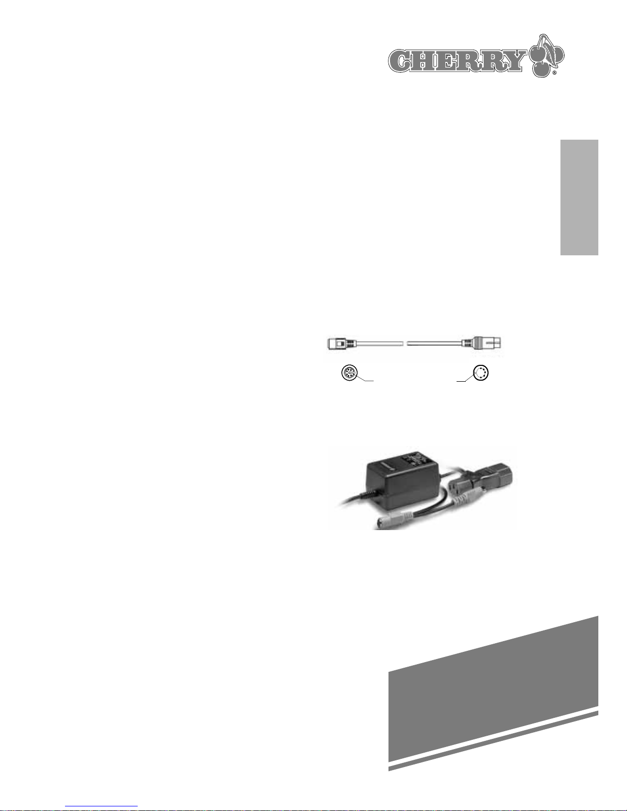
9. Zubehör
Adapterkabel 6polig Mini DIN,
5polig DIN (Nr. 617-0848)
Power pack (Nr. 636-0151)
Download-Software:
Internet: http://www.cherry.de
7
-Lagertemperatur: -20°C bis +60°C
-Betriebstemperatur: 0°C bis 50°C
-Schnittstelle:
IBM-kompatible Tastaturschnittstelle
PS/2;
Serielle Schnittstelle 9-polig SUB-DStecker
Parallele Schnittstelle 25-polig-SUB-DStecker
-Datenausgänge: Open Collector TTL
-Datenformat: Der Datentransfer zu
und von der Tastatur erfolgt im
IBM-synchronen Format.
-Abmessungen:
Modellreihe 12000/12100:
470 x 220 x 61 mm
8. Fehlerbeseitigung
Achtung!
➭ Versuchen Sie nicht, die Tastatur
selbst zu öffnen und zu reparieren.
- Fehlermeldungen nach dem Hochlauf
oder zusammenhanglose Zeichen am
Bildschirm:
➭ Bitte prüfen Sie die Verbindung zwi-
schen der Tastatur und dem Computer.
- Wenn die Tastatur nicht einwandfrei
funktioniert:
➭ Alle Verbindungen prüfen; häufig sind
Störungen auf lose Kabel und Anschlüsse zurückzuführen.
- Wenn das Chipkarten-Terminal nicht
einwandfrei funktioniert:
➭ Prüfen Sie, ob Chipkarte richtig in den
Leser eingelegt ist; sie muß vollständig
und in der richtigen Richtung
eingeführt sein.
➭ Schnittstelleneinstellungen der Soft-
ware am PC prüfen und ggf.
verändern.
shell
shell
1
2
3
4
5
6
1
2
3
4
5
Deutsch

8
Table of Contents
Page
Description of illustration ______________________________________________________9
Scope of this user guide ______________________________________________________9
1. General Advice _________________________________________________________9
2. Introduction ___________________________________________________________10
2.1 General description of keyboard ________________________________________10
2.2 Fingerprint module ____________________________________________________10
2.3 Smartcard reader unit _________________________________________________10
2.4 Core plus FPR model __________________________________________________10
2.5 Single Core FPR model ________________________________________________10
3. Installation_____________________________________________________________10
3.1 System requirements _________________________________________________10
3.3.1 G 81-12000LTB... _____________________________________________________11
3.3.2 G 81-12000LTC.../LVD _________________________________________________11
3.2 Software ____________________________________________________________11
3.3 Smartcard reader installation instructions_________________________________11
4. How to use the integrated smartcard terminal _____________________________12
4.1 Inserting the smartcard ________________________________________________12
4.2 Inserting the plug-in cards _____________________________________________12
5. Firmware _____________________________________________________________12
6. Status indicators _______________________________________________________12
6.1 Model Single Core-FPR ________________________________________________13
7. Technical specifications _________________________________________________13
7.1 Technical specifications of the keyboard _________________________________13
8. Troubleshooting ________________________________________________________13
9. Accessories ___________________________________________________________14

9
Description of illustration
➭Key to drawing on page III
12000/12100 keyboard family
➀ Smartcard reader slot (vertical)
➁ Fingerprint module
➂ Status indicators (LEDs)
➃ Keyboard cable
➄ Plug-in port cover
➅ Adjustable feet
➆ 25pin SUB-D connector for fingerprint
module
➇ 9pin SUB-D connector
➈ PS/2 keyboard connector
➉ Pass-through connector (alternatively)
Plug-in card reader
➊ Plug-In housing
➋ Locking device
➌ Beveled edges
➍ Guide rails
Cherry data input devices are renowned
for their exceptional quality and reliability.
Developed especially for professional
keyboard applications, Cherry keyboards
incorporate the latest market trends and
ergonomic findings. Based on mature
and innovative technology, Cherry’ s
user-friendly products are ideal for applications in offices and IT departments.
Scope of this user guide
This user guide applies to all keyboards
in the Cherry 12000/12100 family.
1. General Advice
Cherry's continual developments ensure
products that are fully optimised and as
such reserve the right to make any
technical alterations. The establishment
of reliability together with the definition
of technical performance are made
according to Cherry's own requirements
for meeting internationally recognised
standards. Requirements outside of
these can be reached through mutual
co-operation. Improper usage, handling,
storage and external influences could
lead to disturbances and defects during
use. We do not grant or warrant any
alterations to our product by the user in
any capacity and do not accept any
liability for unauthorized modifications.
All repairs must be made by Cherry or
an officially appointed organisation or
persons. To avoid danger of explosion,
the optional lithium battery may only be
exchanged by an expert. Possible compensation claims against Cherry or it's
nominated officers whatever the legal
justification including physical or stress
related injuries are not possible with the
exception of negligence on our behalf,
and governing Product Liability Law.
These notices & operating instructions
only apply to the accompanying product.
Further details of this can be obtained
from your local Cherry dealer or directly
from Cherry GmbH.
Latest information please see
Internet: http://www.cherry.de
English

2. Introduction
2.1 General description of
keyboard
Cherry keyboards in the G81-12000/12100
family, including our FPR 12000/FPR
12100, Core Plus FPR and Single Core
FPR models, belong to a new generation
of biometric keyboards also with integrated smartcard readers.
2.2 Fingerprint module
The integrated fingerprint module is
capable of scanning each user’ s fingerprints into the connected system. The
module is connected to the PC’ s printer
interface (parallel port) through a 25-pin
SUB-D connector. With the pass-through
connector
➉ you are still able to use your
printer.
Important:
Make sure that the parallel port is EPP
or ECP-compliant and has been set to
operate in one of these two modes.
You can check this setting in BIOS by
pressing the F10 or DEL key while the
PC is booting up.
2.3 Smartcard reader unit
The integrated smartcard reader unit is
capable of scanning and describing
smartcards in compliance with the DIN
ISO/IEC 7816 standard.
2.4 Core Plus FPR model
Keyboard with integrated smartcard
terminal based on GEMCORE by
Gemplus. The keyboard can be fitted
10
with the following components: 1 main
card reader, 4 SIMM modules, 4 Mbit
flash RAM for code, 4 Mbit flash RAM
for data, 128 kbit RAM, real-time clock,
battery buffer for RTC and RAM, RS 232
interface. Power is supplied through the
keyboard port. The necessary driver
software can be obtained from the
Gemplus Internet website at
http://www.gemplus.com.
2.5 Single Core FPR model
Keyboard G 81-12000 LTC..
Keyboard G 81-12000 LVD..
3. Installation
3.1 System requirements
The keyboards were designed for use
with IBM AT, PS/2 or 100%-compatible
computers.
Warning!
Smartcards may contain data of considerable financial value as well as confidential
or personal (encryption) keys or codes.
Please take appropriate precautions
against theft and misuse!
Please check that your PC has a 100%
IBM-compatible keyboard interface capable
of supplying at least 200 mA
.
If this is not the case, you MUST use
the Cherry external power pack
(cf. Accessories), otherwise you may
cause damage to your PC’ s motherboard
or other components.
To install the keyboard, proceed as follows:
➭ Switch off your computer
➭ Unplug the existing keyboard

11
English
➭ Plug in the Cherry keyboard ➈
➭ Insert the 9-pin SUB-D connector ➇ for
the smartcard reader into one of your
computer’s COM ports (serial port)
➭ Insert the 25-pin SUB-D connector ➆
into your computer’s printer port
(parallel port)
➭ If your computer’s keyboard interface
does not supply enough power to run
the keyboard, plug in the external
power supply
➭ Switch the computer on again.
When the computer is switched on, both
computer and keyboard perform a selfdiagnostic test. Once the self-test is
complete and the operating system has
been loaded, you can start to work with
the keyboard. Please check that the
keyboard is functioning correctly. If an
error message appears when you switch
on your computer, or if scrambled
characters appear on-screen, please
make sure that the keyboard is properly
connected to the computer and that all
other connections are firmly in place.
3.2 Software
The keyboard supports a variety of
software applications. Please read the
relevant user instructions for each
software application. More information
on the standard software supplied by
Cherry is available from the Cherry
website at: http://www.cherry.de.
3.3 Smartcard reader installation
instructions
3.3.1 G 81-12000LTB...
Kindly install the latest drivers from the
Gemplus Homepage:
➭ Visit the following internet page:
http://www.gemplus.com/
products/hardware/drivers.htm
➭ Register on Gemplus Developer's Site.
➭ You will find on the Driver Download
Page the table „PC/SC Drivers“ and
the file „PC SC_Reader_install.exe“
➭ Execute the installation for the reader
GCR 410.
3.3.2 G 81-12000LTC.../LVD...
The integrated smartcard terminal was
developed in compliance with the PC/SC
(Personal Computer Smart Card
Workgroup – http://www.pcscworkgroup.
com) specification, meaning that it is
ideal for developers who want to produce
smartcard-based PC applications. Using
the appropriate driver or IFD (Interface
Device) handler, the card terminal can be
integrated with the PC’s operating system.
You will find the associated drivers for
the different operating systems either on
the data carrier included with the product, or the latest versions on our web
site in the Internet at:
http://support.cherry.de

12
The Plug & Play function incorporated in
the operating system is supported by the
optional enclosed “Installation Disk“. To
install the driver, follow the instructions
displayed on the screen on booting.
The product is listed by Microsoft in the
Windows Hardware Compatibility List
(WHQL) as “Smart Card Keyboard“.
4. How to use the
integrated smartcard
terminal
4.1 Inserting the smartcard
Symbols on the keyboard housing show
you which way round to hold the smartcard when inserting it into the reader:
– Vertical card reader:
Insert the smartcard with the chip at
the bottom, facing the user.
To ensure that the smartcard slots into
the proper position for scanning,
the user
must push the card past an action point,
involving some initial resistance.
4.2 Inserting the plug-in cards
In addition to conventional card formats,
payment transaction and security
systems also use smaller cards that are
usually left in place for lengthy periods of
time. Usually known as plug-in cards,
they can be slotted into the underside of
the keyboard.
Careful!
Voltage spikes in the plug-in socket can
destroy plug-in cards, causing all data to
be lost.
➭ Always switch off the PC before
inserting or swapping a plug-in card
➭ Fold out the diagram in the front of the
user manual
➭ Turn the keyboard over (cable duct
uppermost; cf. diagram)
➭ Gently push down the fin on the cover
➄ and open the cover.
➭ Open the plug-in housing ➊ inside. To
do so, push the locking device ➋
upwards in the direction of the arrow
and carefully open the lid.
➭ If the plug-in card was delivered in a
carrier card, remove the plug-in card
from its carrier card.
– Please refer to the relevant software
documentation for instructions on how
to assign plug-in cards to the appropriate
plug-in housing!
– Make sure you insert the card the right
way up! Plug in cards should be inserted
straight edge first and with the chip
uppermost (cf. ➌).
5. Firmware
he keyboard is supplied with standard
firmware for processing all card reader
and keyboard functions. This firmware
can be customized to your needs by
agreement with Cherry GmbH.
6. Status indicators
Whenever the PC is switched on or
rebooted, the keyboard peforms a self-

13
English
diagnostic test; all LEDs flash once, briefly.
In normal operation, the LEDs indicate
the status of the keyboard.
6.1 Model Single Core-FPR
Smart card switch on is explicitly
indicated by the green LED with Chipcard symbol. “Secure Pin Entry“ mode is
signalled by the red flashing Pin LED. In
this mode it is possible to send the PIN
entered using the numeric keypad
directly to the smart card.
7. Technical specifications
7.1 Technical specifications of the
keyboard
– Power supply:
+5 volts ±5% SELV
– Current input:
max. 200 mA
– Typematic function:
All keys have an autorepeat function.
Delay and frequency can be set from
the system.
– Power-on reset:
The keyboard automatically resets itself
at power-on.
– Keyboard self-test:
When current is applied or at the
system’s request, the keyboard performs
a self-diagnostic test. If the test is
successful, the keyboard returns the
hexadecimal code AA. Any other code is
interpreted as a fault.
– Storage temperature: -20°C to +60°C
– Operating temperature: 0°C to +50°C
– Interfaces:
IBM PS/2-compatible keyboard interface:
9-pin SUB-D serial port connector;
25-pin SUB-D parallel port connector
– Data outputs:
Open collector TTL
– Data format:
Data is transferred to/from the keyboard
in IBM synchronous format
– Dimensions:
12000/12100 keyboard family:
470 x 220 x 61 mm
8. Troubleshooting
Warning!
➭ Do not attempt to open and repair the
keyboard yourself.
– If error messages or scrambled
characters appear on-screen when the
computer is switched on:
➭ Check that the keyboard is properly
connected to the computer system.
– If the keyboard is not working properly:
➭ Check all connections; loose cables
and connectors are a common source
of faults.
– If the smartcard reader is not working
properly:
➭ Check that the smartcard is positioned
correctly in the reader; make sure it is
fully inserted and the right way round.
➭ Check the interface (port) settings in
the software on the PC and change
them if necessary.

➭ Reboot the PC and note down the
flashing code (cf. Status indicators);
call a service engineer or follow the
procedure described in section 4 and
then try again.
➭ Check the smartcard’s make, model
and functions.
➭ If you suspect that the fault may be
due to an incompatible driver, please
contact your dealer.
9. Accessories
6-pin mini-DIN/5-pin DIN adapter cable
(stock code 617-0848)
Power pack (stock code 636-0151)
Download software from:
Cherry website at http://www.cherry.de/
14
shell
shell
1
2
3
4
5
6
1
2
3
4
5

15
Table des matières
Page
Description du dessin _______________________________________________________16
Champ d’application de ce manuel ____________________________________________16
1. Généralités ____________________________________________________________17
2. Introduction ___________________________________________________________17
2.1 Description générale du clavier__________________________________________17
2.2 Module de reconnaissance d’empreinte digitale___________________________17
2.3 Unité de lecture de cartes à puce _______________________________________17
2.4 Modèle core Plus FPR _________________________________________________17
2.5 Modèle Single Core FPR _______________________________________________17
3. Installation_____________________________________________________________17
3.1 Configuration de base _________________________________________________17
3.2 Logiciel ______________________________________________________________18
3.3 Installation du lecteur de cartes à puce___________________________________18
3.3.1 G 81-12000LTB... _____________________________________________________18
3.3.2 G 81-12000LTC.../LVD _________________________________________________18
4. Comment utiliser le terminal cartes à puce ________________________________19
4.1 Insertion de la carte à puce_____________________________________________19
4.2 Mise en place des cartes SIM __________________________________________19
5. Logiciel _______________________________________________________________20
6. Indicateurs d'état ______________________________________________________20
6.1 Modèle Single Core-FPR _______________________________________________20
7. Caractéristiques techniques ______________________________________________20
8. Détection des pannes___________________________________________________21
9. Accessoires ___________________________________________________________21
English
Français

16
Description du dessin
➭Explication du schéma en p. III
Clavier de la série 12000/12100
➀ Lecteur de cartes à puces (vertical)
➁ Module de reconnaissance
d’empreinte digitale
➂ Indicateurs d’état (LED)
➃ Câble clavier
➄ Trappe d’accès carte SIM
➅ Pieds réglables
➆ Connecteur Sub-D 25 points pour le
module de reconnaissance
d’empreinte digitale
➇ Connecteur Sub-D 9 points
➈ Connecteur clavier PS/2
➉ Connecteur multifonction
(fakultativement)
Lecteur de cartes SIM
➊ Boîtier pour cartes SIM
➋ Système de blocage
➌ Bord chanfreiné
➍ Guides
Les systèmes de saisie Cherry sont
renommés pour leur qualité et leur
fiabilité exceptionnelles.
Les claviers Cherry ont été développés
tout spécialement pour des applications
professionnelles, en tenant compte des
plus récentes tendances du marché et
des principes d’ergonomie.
Ils offrent une technique innovante, d’un
grand confort, pour des applications
réussies en bureautique et dans la
communication multimédia.
Champ d’application de ce
manuel
Tous les claviers de la série 12000/12100.
1. Généralités
Cherry optimise continuellement ses
produits en fonction des progrès
technologiques. Par conséquent, nous
nous réservons le droit de faire des modifications techniques. La fiabilité ainsi que la
définition des détails techniques sont le
résultat de tests internes conformes aux
normes internationales en vigueur. De
mauvaises conditions
d’utilisation, de stockage, ou d'environnement peuvent entraîner
des dysfonctionnements lors de l’utilisation.
Nous insistons sur le fait que nous ne pouvons accorder quelque garantie que ce soit
pour toute modification du matériel par
l’utilisateur sauf si elle a été approuvée par
nos soins (par écrit) dans le cas d’une
utilisation spécifique. Ceci est valable
également pour les éventuels travaux de
réparation ou de maintenance effectués
par des personnes non agréées. Il existe
un danger d’explosion en cas de remplacement non conforme de la pile en lithium
fournie en option. Toute éventuelle demande
d’indemnisation sera rejetée dans la mesure
où elle n’est pas la conséquence d’une
négligence de notre part. La restriction
ci-dessus ne s’applique pas dans le cadre
de la loi sur la Responsabilité Produit. Les
conditions d’utilisation ci-dessus ne sont
valables que pour le produit livré avec
cette notice. Pour tout complément
d’information, veuillez contacter votre
revendeur ou directement Cherry GmbH.
Les informations les plus actuelles
sont disponibles sur le site web
Cherry: http://www.cherry.de

17
Français
2. Introduction
2.1 Description générale du
clavier
Les claviers Cherry de la série 12000/12100,
tels que les modèles FPR 12000/FPR
12100, Core Plus FPR et Single Core FPR,
appartiennent à une nouvelle génération
de claviers biométriques de même avec
lecteurs de cartes intégrés.
2.2 Module de reconnaissance
d’empreinte digitale
Le module de reconnaissance d’empreinte
digitale intégré est capable de reconnaître
et d’envoyer au sysème l’empreinte
digitale de chaque utilisateur. Le module
est relié au port parallèle du PC par un
connecteur Sub-D 25 points. Vous pouvez
toujours utiliser votre imprimante par le
connecteur multifonction
➉ .
Important:
Assurez-vous que le port parallèle est
compatible EPP ou ECP et a été
programmé pour fonctionner dans l’un de
ces 2 modes.
Vous pouvez le vérifier dans le BIOS en
appuyant sur les touches F 10 ou DEL lors
de l’initialisation de votre PC.
2.3 Unité de lecture de cartes à
puce
L’unité de lecture de cartes à puce est
capable de lire et décoder les cartes à
puce conformes à la norme DIN ISO /
IEC 7816.
2.4 Modèle Core Plus FPR
Clavier avec terminal cartes à puce basé
sur la technologie GEMCORE de
Gemplus.Le clavier peut être équipé des
éléments suivants: 1 lecteur de carte
principal,
4 modules SIMM, une RAM flash de
4 Mbit pour l’encodage, une RAM flash
de 4 Mbit pour les données, une RAM
de 128 kbit, une horloge en temps réel,
une batterie tampon pour l’horloge et les
RAM, une interface RS 232.
L’alimentation est fournie via le port
clavier.
Le driver nécessaire peut être téléchargé
à partir du site web Gemplus à l’adresse
suivante: http://www.gemplus.com
2.5 Modèle Single Core FPR
Clavier G 81-12000 LTC..
Clavier G 81-12000 LVD..
3. Installation
3.1 Configuration de base
Ces claviers on été conçus pour être
utilisés avec des systèmes IBM AT, PS/2
ou compatibles à 100%.

18
Attention!
Les cartes à puce peuvent contenir des
données d’une valeur financière
considérable, des données confidentielles
ou des codes personnels (encryptage).
Prenez donc les précautions nécessaires
contre tout risque de vol ou d’utilisation
mal intentionnée.
Vérifiez avant tout que votre PC possède
une interface clavier 100% compatible
IBM pouvant fournir au moins 200 mA.
Si ce n’est pas le cas, vous Devez
utiliser l’alimentation externe Cherry (cf.
Accessoires); dans le cas contraire, vous
pourriez endommager la carte mère de
votre PC ou d’autres composants.
Pour installer le clavier, procédez comme
suit:
➭ Eteignez votre ordinateur
➭ Débrancher l’ancien clavier
➭ Branchez le clavier Cherry ➈
➭ Insérez le connecteur Sub-D 9 points
pour le lecteur de cartes à puce dans
l’un des ports COM de votre
ordinateur (port série).
➭ Insérez le connecteur Sub-D 25 points
dans le port imprimantes de votre
ordinateur (port parallèle).
➭ Si l’interface clavier de votre ordinateur
ne fournit pas assez de courant pour
alimenter le clavier, branchez l’alimentation
externe.
➭ Rallumer votre ordinateur.
Lorsque l’ordinateur est allumé, le clavier
et l’ordinateur effectuent un test de
diagnostic. Lorsque ce test est terminé
et que le système d’exploitation est chargé,
vous pouvez commencer à travailler avec
le clavier.
Vérifiez que le clavier fonctionne
correctement.
Si un message d’erreur apparaît lorsque
vous allumez votre ordinateur, ou si des
caractères aléatoires s’affichent sur
l’écran, assurez-vous que le clavier est
bien branché est que les autres
connexions sont bien établies.
3.2 Logiciel
Le clavier accepte de nombreux logiciels
d’application. Lisez les instructions
concernant l’utilisation d’un logiciel
d’application.
D’autres informations concernant le
logiciel standard fourni par Cherry sont
disponibles sur le site web Cherry à
l’adresse http://www.cherry.de
3.3 l’Installation du lecteur de
cartes à puce
3.3.1 G 81-12000LTB...
Installer le driver le plus récent à partir de
l'Homepage Gemplus:
➭ Appeler la page Internet
http://www.gemplus.com/products/
hardware/drivers.htm
➭ Entrer les données demandées
➭ Sur la page Download, vous trouverez
le fichier ”PC SC_Reader_install.exe“
sous le tableau ”PC/SC Drivers”
➭ Effectuer l'installation pour le lecteur
GCR 410.
3.3.2 G 81-12000LTC.../LVD...
Le lecteur de cartes à puce intégré, qui a
été mis au point d’après la norme PC/SC
(Personal Computer Smart Card
Workgroup= groupe de travail sur les
cartes à puce des ordinateurs

19
Français
Pour être sûr que la carte est dans la
position idéale pour la lecture,
l’utilisateur doit pousser la carte au delà
d’un »point dur«, ce qui suppose une
résistance initiale.
4.2 Mise en place des cartes SIM
En plus des formats de cartes traditionnels,
les systèmes de transactions bancaires
et de sécurité utilisent également de plus
petites cartes qui restent généralement
en place pendant de longues périodes.
Habituellement appelées cartes SIM,
elles peuvent être positionnées sous le
clavier.
Attention!
Les sautes de tension dans le support de
carte peuvent endommager les cartes
SIM, entraînant la perte des informations.
➭ Eteignez toujours votre ordinateur
avant de mettre en place ou d’enlever
une carte SIM.
➭ Consulter le diagramme au début du
manuel d’utilisation.
Retournez le clavier (Guide câble
au-dessus; voir diagramme).
personnels– http://www.pcscworkgroup.
com), permet de réaliser des applications
sur PC à I’aide de cartes à puce. Un
gestionnaire IFD (Interface Device,
périphérique d’interface) permet
d’intégrer le lecteur de cartes à puce
dans le système d’exploitation du PC.
Vous trouverez les pilotes pour les différents systèmes d’exploitation soit sur
le support de données joint au produit,
soit sur nos sites Web sur Internet, sous:
http://support.cherry.de
La fonction Plug & Play intégrée au
système d’exploitation est supportée par
le «Installation Disk» joint en option. Pour
l’installation des pilotes, suivez les messages affichés à l’écran lors du chargement.
Le produit figure dans la Windows
Hardware Compatibility List (WHQL) de
Microsoft en tant que «Smart Card
Keyboard».
4. Comment utiliser le
terminal cartes à puce
4.1 Insertion de la carte à puce
Les symboles sur le boîtier du clavier
montrent comment tenir la carte lors de
l’insertion dans le lecteur.
Lecteur de cartes à puce vertical:
Lorsque vous insérez la carte, la puce
doit être positionée en bas, face à
l’utilisateur.

20
➭ Poussez doucement l’onglet situé sur
le boîtier ➄ et ouvrez le boîtier.
➭ Ouvrez le boîtier pour cartes SIM
➊ situé à l’intérieur du clavier.
Pour cela, poussez l e système de
fermeture ➋ vers le haut comme
l’indique la flèche et ouvrez le couvercle.
➭ Si la carte SIM vous a été livrée sur
une carte-support, retirez d’abord cette
carte support.
– Référez-vous à la documentation pour
avoir des instructions concernant
l’assignation des cartes à insertion
dans le boîtier approprié.
– Assurez-vous que vous insérez la carte
dans le bon sens; la carte doit être
insérée du côté rectiligne, puce
au-dessus (cf. ➌).
5. Logiciel
Le clavier est fourni avec un logiciel standard assurant le fonctionnement de tous
les types de lecteurs de cartes, et des
fonctions du clavier.
Ce logiciel peut être personnalisé en
fonction de vos besoins en accord avec
Cherry GmbH.
6. Indicateurs d’état
Lorsque vous allumez votre PC ou lors
d’une réinitialisation, le clavier établit un
autotest. Toutes les LED s’allument alors
pendant un court instant.
Durant le fonctionnement normal du clavier, les LED indiquent les états.
6.1 Modèle Single Core-FPR
La activation de la carte à puce est indiquée clairement par la LED verte avec le
symbole de carte à puce. Le mode
«Secure-PIN-Entry» est signalé par le clignotement de la LED PIN rouge. Dans ce
mode, le Pin entré par le pavé numérique
peut être envoyé directement à la carte à
puce.
7. Caractéristiques
techniques
– Alimentation:
+5 volts ±5% (SELV : très basse
tension de sécurité).
– Consommation typique:
200 mA max.
– Fonction répétition automatique:
Toutes les touches disposent de la
fonction répétition automatique. Le
délai et la fréquence de répétion
peuvent être programmés à partir du
système.
– Autotest clavier:
Dès que l’on met en route l’alimentation
ou selon les besoins du système, le
clavier établit un autotest. Si le test est
réussi avec succès, le clavier transmet
alors le code hexadécimal AA. Tout autre
code est interprété comme une erreur.
– Plages de températures:
Stockage: -20°C à + 60°C
Fonctionnement: 0°C à + 50°C
– Interface:
Interface clavier compatible IBM PS/2.
Connecteur port série Sub-D 9 points
Connecteur port parallèle Sub-D 25
points.
– Sorties de données:
Collecteur ouvert TTL.
– Format données:
Le transfert de données du clavier au
système et inversement se fait dans
un format synchrone IBM.
– Dimensions:
Clavier de la série 12000/12100:
470 x 220 x 61 mm.

21
Français
8. Détection des pannes
Attention :
N’essayez pas d’ouvrir ou de réparer le
clavier vous-même.
Si des messages d’erreur ou des
caractères aléatoires apparaissent à
l’écran lorsque l’ordinateur est allumé:
➭ Vérifiez que le clavier est correctement
connecté au système.
Si le clavier ne fonctionne pas
correctement:
➭ Vérifiez les connections; les
connecteurs et câbles débranchés sont
des sources d’erreurs très fréquentes.
Si le lecteur à puces ne fonctionne pas
correctement:
➭ Vérifiez que la carte est correctement
positionnée dans le lecteur. Assurez-
vous qu’elle est insérée entièrement
et dans le bons sens.
➭ Vérifiez la déclaration des ports dans le
PC et modifiez-les si nécessaire.
➭ Rebootez le PC et notez l’état des
LED. Appelez un technicien ou référez-
vous à la procédure décrite dans le
point 4, puis essayez de nouveau.
➭ Vérifiez l’origine, le modèle et les fonc-
tions du lecteur de cartes.
➭ Si vous pensez que l’erreur peut être
due à un driver incompatible, contactez
votre revendeur.
9. Accessoires
Câble adaptateur 6 broches mini-DIN / 5
broches DIN (référence : 617-0848).
Kit d’alimentation (référence: 636-0151)
Logiciel de chargement disponible sur le
site web de Cherry à l’adresse suivante:
http://www.cherry.de
shell
shell
1
2
3
4
5
6
1
2
3
4
5

22
Canadian Radio Interference
Regulations
Notice of CSA C 108.8 (DOC Jan. 1989)
This digital apparatus does not exceed the
Class A limits for radio noise emissions from
digital apparatus set out in the Radio
Interference Regulations of the Canadian
Department of Communications.
Le présent appareil numérique n'émet pas de
bruits radioélectriques dépassant les limites
applicables aux appareils numériques de la
classe B prescrites dans le Réglement sur le
brouillage radioélectrique édicté par le
ministère des Communications du Canada.
Hinweis zum GS-Zeichen
Aufgrund der Position der Nulltaste des
numerischen Bereiches ist die Tastatur für
Saldiertätigkeiten, die überwiegend blind
erfolgen, in Deutschland nicht anzuwenden.
Eine Tastatur mit nicht deutscher Tastenknopfbelegung ist in Deutschland aufgrund
der Zeichenbelegung (nach DIN 2137 Teil 2)
nicht für den Dauereinsatz in Bildschirmarbeitsplätzen zu verwenden. Um die
Anforderungen für das GS-Zeichen auf der
Basis DIN EN 9241-4 (1999-01) zu erfüllen, ist
eine Tastenrückinformation erforderlich. Um
diese im Bedarfsfall zu realisieren, ist das
Betriebssystem anzupassen bzw. durch eine
entsprechende Shareware/Freeware zu
modifizieren.
CE Declaration of Conformity
We, Cherry GmbH, declare that the
Keyboards, are in conformance with: Low
Voltage Directive 73/23/EEC tested in
accordance with EN 60950. Also that the EMC
Directive 89/336/EEC has been fullfilled to
– EN 50082-1:1997, including
– EN 61000-4-2 : 1995,
– EN 61000-4-3 : 1996,
– EN 61000-4-6 : 1996.
ENV 50204 : 1995 and that of EN 55022 :
1994 + Corrigendum 1997 + A 1 : 1995 +
A 2 : 1997, Class B has been conformed too.
Federal Communications
Commission (FCC) Radio
Frequency Interference
Statement
Information to the user: This equipment has
been tested and found to comply with the
limits for Class B digital device, pursuant to
Part 15 of the FCC Rules. These limits are
designed to provide reasonable protection
against harmful interference in a residential
installation. This equipment generates, uses
and can radiate radio frequency energy and, if
not installed and used in accordance with the
instructions, may cause harmful interference
to radio communications. However, there is
no guarantee that interference will not occur
in a particular installation. If this equipment
does cause harmful interference to radio or
television reception, which can be determined
by turning the equipment off and on, the user
is encouraged to try to correct the
interference by one or more of the following
measures:
- Reorient or relocate the receiving antenna
- Increase the separation between the
equipment and receiver
- Connect the equipment into an outlet on a
circuit different from that to which the
receiver is connected
- Consult the dealer or an experienced
radio/TV technician for help
Caution: Cherry is not responsible for any
radio or television interference caused by
unauthorized modifications of this equipment
or the substitution or attachment of
connecting cables and equipment other than
those specified by Cherry! Such unauthorized
modifications, substitutions, or attachments
may void the user’s authority to operate the
equipment. The correction of interferences
caused by such unauthorized modifications,
substitutions, or attachments will be the
responsibility of the user. Use only shilded
interface cables to ensure compliance.

23
24
24
24
25
25
25
25
25
25
25
26
26
26
26
27
27
27
27
28
28
28
28
28
29
29

24

25

26

27

28

29
shell
shell
1
2
3
4
5
6
1
2
3
4
5
shell
shell
1
2
3
4
5
6
1
2
3
4
5

30
31
32
32
32
32
33
33
33
33
33
34
34
35
35
35
36
36
36
36
37
38

31

32

33

34

35

36

37

38
shell
shell
1
2
3
4
5
6
1
2
3
4
5
shell
shell
1
2
3
4
5
6
1
2
3
4
5

Cherry GmbH
Cherrystraße
D-91275 Auerbach/Opf.
Hotline: (0 9643) 18-206
Telefax: (09643) 18-262
Internet: http://www.cherry.de
644-0182.02
Irrtum und technische
Änderungen vorbehalten.
Gedruckt in der
Bundesrepublik Deutschland.
45331775
D,E,F,J,C, April. 2000,1, Wir
©2000 Cherry GmbH
 Loading...