

Page 1
802.11b 11Mbps
Wireless Access Point
User’s Manual
Page 2

Table of Content
CHAPTER1 INTRODUCTION......................................................................................................... 4
1.1 P
ACKAGE CONTENT .......................................................................................................... 4
1.2 SYSTEM REQUIREMENT .................................................................................................... 4
1.3 W
IRELESS ACCESS POINT SPECIFICATION ......................................................................... 4
1.4 WIRELESS ACCESS POINT HARDWARE DIAGRAM................................................................ 5
CHAPTER2 QUICK SETUP............................................................................................................7
2.1 C
ONNECTING THE ACCESS POINT ..................................................................................... 7
2.2 CONFIGURING ETHERNET ADAPTER SETTING..................................................................... 7
2.3 CONFIGURING THE ACCESS POINT – BASIC SETTINGS ..................................................... 10
2.4
APPLICATION SCENARIO .................................................................................................. 12
CHAPTER3 USING THE CONFIGURATION UTILITY................................................................. 16
3.1 O
3.2 C
3.3 B
PEN THE CONFIGURATION UTILITY................................................................................. 16
ONFIGURATION UTILITY – HOME PAGE........................................................................... 17
ASIC SETUP ................................................................................................................. 17
3.4 ADVANCED SETUP .......................................................................................................... 20
3.5 MANAGEMENT SETUP ..................................................................................................... 23
3.6 A
BOUT ........................................................................................................................... 27
CHAPTER4 BRIDGE MODE CONFIGURATION......................................................................... 29
4.1 H
OME MENU .......................................................................................................................... 29
4.2 W
IRELESS MENU.................................................................................................................... 30
4.3 BRIDGE MENU........................................................................................................................ 32
4.4 SITE SURVEY MENU ............................................................................................................... 32
4.5 A
DVANCE MENU ..................................................................................................................... 33
4.6 SELECT MENU ....................................................................................................................... 34
CHAPTER5 TROUBLESHOOTING.............................................................................................. 36
Page 3

Regulatory Compliance
FCC Warning
This device complies with Part 15 of the FCC Rules.
Operation is subject to the following two conditions: (1) this device may not cause harmful
interference, and (2) this device must accept any interference received, including interference that
may cause undesired operation.
This equipment has been tested and found to comply with the limits for a Class B digital device,
pursuant to part 15 of the FCC Rules. These limits are designed to provide reasonable protection
against harmful interference in a residential installation.
This equipment generates, uses and can radiate radio frequency energy and, if not installed and
used in accordance with the instructions, may cause harmful interference to radio communications.
However, there is no guarantee that interference will not occur in a particular installation. If this
equipment does cause harmful interference to radio or television reception, which can be
determined by turning the equipment off and on, the user is encouraged to try to correct the
interference by one or more of the following measures:
Reorient or relocate the receiving antenna.
Increase the separation between the equipment and receiver.
Connect the equipment into an outlet on a circuit different from that to which the receiver is
connected.
Consult the dealer or an experienced radio/TV technician for help.
Changes or modifications not expressly approved by the party responsible for
compliance could void your authority to operate the equipment.
1) To comply with FCC RF exposure compliance requirements, a separation distance of at least
20 cm must be maintained between the antenna of this device and all persons.
2) This transmitter must not be co-located or operating in conjunction with any other antenna or
transmitter.
Page 4

Chapter1
Introduction
1.1 Package Content
Open the box and remove all items, please make sure that you have received the following items:
Wireless Access Point Package Content
1 Wireless Access Point
2 AC Adapter (3.3 VDC)
3 Quick Installation Guide
4 Manual on CD
If any item is found missing or damaged, please contact your local reseller for replacement.
1.2 System Requirement
To properly use your wireless Access Point, please make sure that your laptop or desktop meets
the following minimum system requirements:
The laptop or desktop must have one of the operating systems, i.e: MS Windows 98SE, ME,
2000 and WinXP
CD-ROM drive
At least one computer equipped with an 802.11b compliant wireless Ethernet adapter
TCP/IP networking protocol installed on each computer
Internet Explorer version 5.0 and above or Netscape Navigator version 6.0 and above
1.3 Wireless Access Point Specification
Specification
RF Technology
Operating Frequency
Modulation Schemes
Channel Numbers
Data Rate
Media Access Protocol
Transmitter Output Power
Receiver Sensitivity
Range Coverage
Data Rate
LED Indicator
Antenna Type
Operating Voltage
Temperature
IEEE 802.11b Direct Sequence Spread Spectrum
2400-2497MHz ISM band
DQPSK, DBPSK and CCK
11 channels for United States
13 channels for Europe
14 channels for Japan
11Mbps with fall back rates of 5.5, 2 and 1Mbps
CSMA/CA with ACK
20 dBm typically
Typical -80dBm for 11Mbps @ 8% PER (Packet Error Rate)
Typical -90dBm for 2Mbps @ 8% PER (Packet Error Rate)
Indoor: 35 - 100 meters (depends on environment)
Outdoor: 100 - 300 meters (depends on environment)
11Mbps with fall back rates of 5.5, 2 and 1Mbps
Power, Test, LAN & WLAN
1 x External non-removable; 1 x Internal antenna with
space and directional diversity
3.3 VDC
0 ~ 45 ℃ in operating
-20~70 ℃ in storage
Page 5
Humidity
Dimension
5% ~ 95% Non-condensing
94.8 mm x 68.4 mm x 33.5 mm
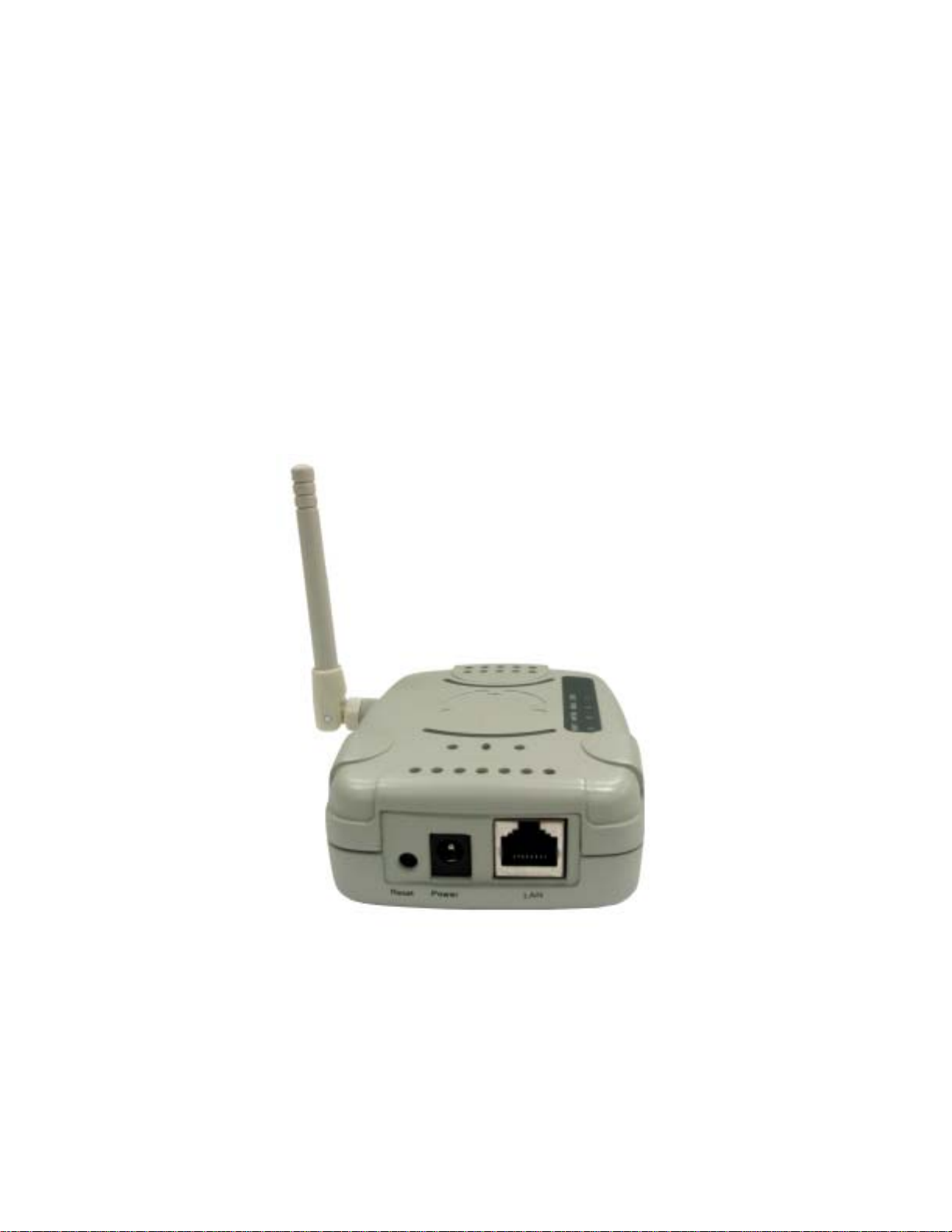
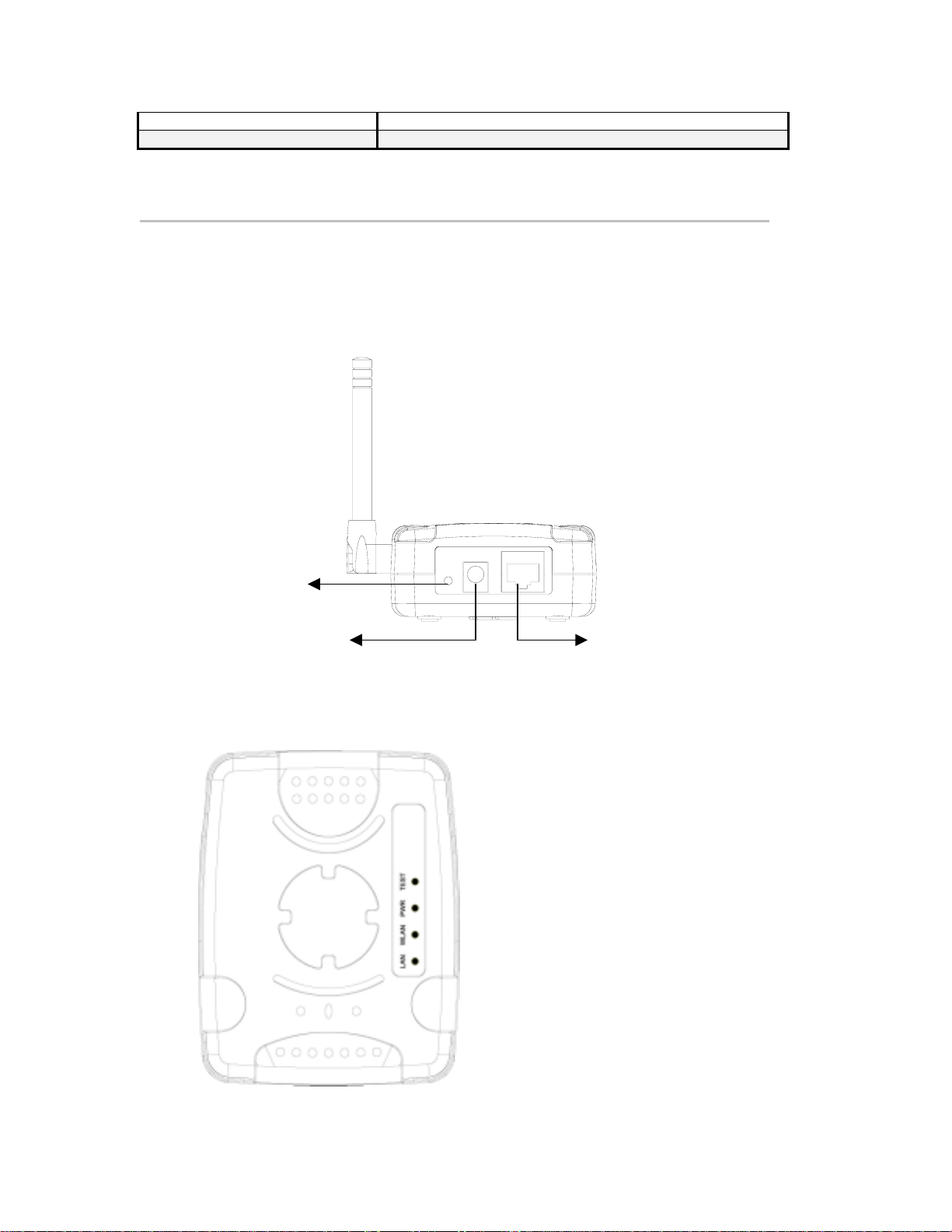
1.4 Wireless Access Point Hardware Diagram
Back Panel
The back of the access point has two connection ports and one rest button:
1. Rest button
2. Power Jack: Power cable connection for 5V adapter
3. LAN Port: Ethernet port
1. Reset Button: Reset to
default setting
2. Power Jack: Connect the
AC/DC Power Adapter.
Top Panel
LAN LED: Indicates that a valid Ethernet
(Wired) cable link.
WLAN LED: Indicates that a valid Wireless
LAN link.
PWR LED: Indicates that the AP is
receiving power.
TEST LED: Indicates the AP’s resetting
status.
3. LAN Port: Connect the RJ-45
Ethernet Cable. Connect an
Ethernet cable to this socket, and
connect to an open RJ45 port on
a switch or hub.
Page 6

LED Indication
LAN
WLAN
PWR
Test
On Blink Off
Ethernet Cable is plugged in
and there is a valid network
connection.
Detecting a valid WLAN link. Detecting Wireless LAN
Unit is plugged in and
working normally
Press the Reset button and
the LED illuminates for 5
sec.
N/A
network activities.
N/A Unit is not plugged in
The unit is resetting. The unit is OFF.
Ethernet cable is not
plugged in or the unit is
OFF.
No Wireless LAN
network available in the
vicinity.
and it is OFF.
Page 7
t
Chapter2
Quick Setup
2.1 Connecting The Access Point
1. Connect one end of the power adapter to the power
jack of the AP and the other end of the power adapter
to an electrical outlet. The PWR LED illuminates
steady green.
2. Connect one end of the Ethernet cable to the LAN por
of the AP and the other end of the Ethernet cable to
the Ethernet port of the computer-equipped with an
Ethernet adapter, a cable/DSL router, Ethernet switch
or hub. The LAN LED illuminates steady green
2.2 Configuring Ethernet Adapter Setting
The initial configuration of the access point must be done through Ethernet port and you have to
assign an IP address for your computer equipped with an Ethernet adapter first. Please follow the
following steps to obtain an IP address.
Note: The following screenshots a re taken in Windows 2000. For other OS, the configuration
procedure will be exactly the same but the screenshots will vary.
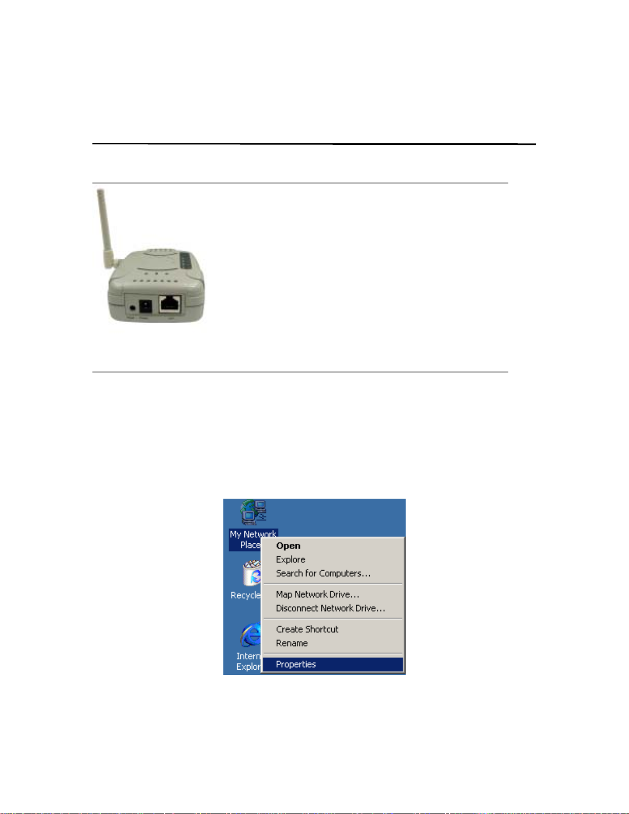
1. Right-click mouse button on the My Neighborhood icon on your Windows desktop and select
Properties from the short-cut menu.
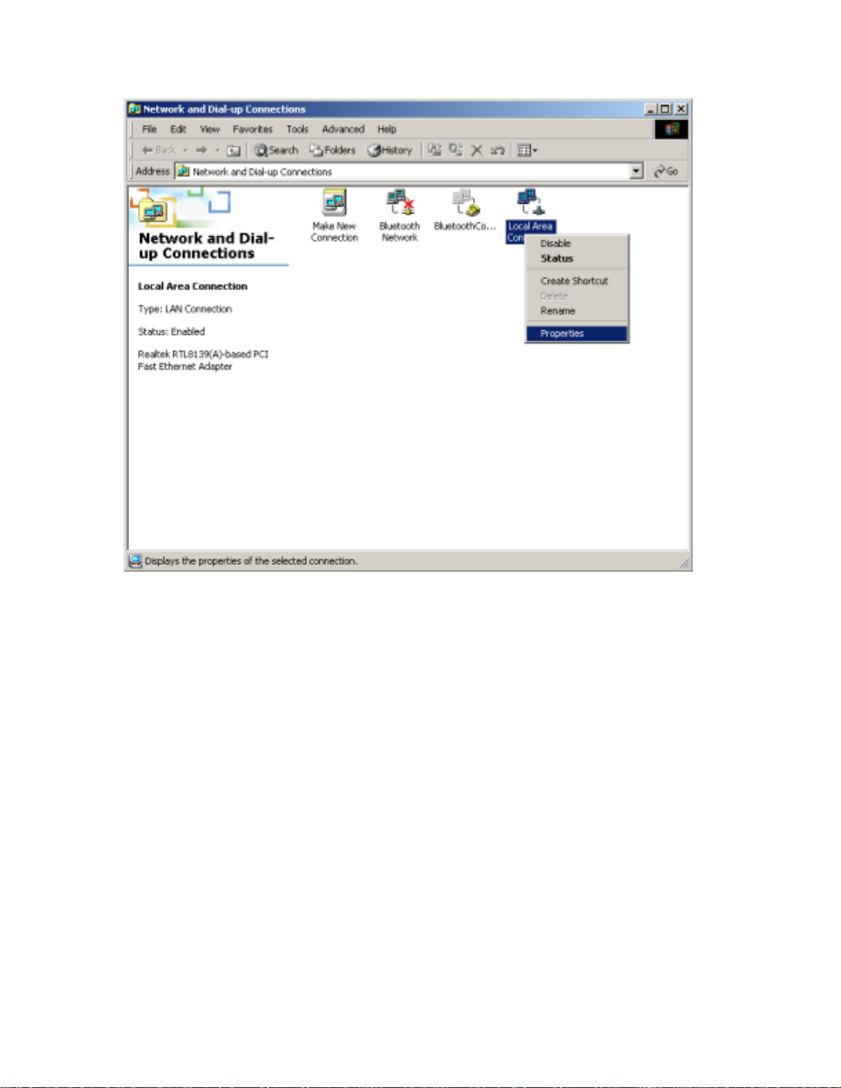
2. Right-click the Local Area Connection for the Ethernet Adapter equipped on your computer
and select Properties from the shortcut menu.
Page 8
3. Click the General tab of the Location Area Connection dialog box, select Internet Protocol
(TCP/IP) and click Properties.
Page 9
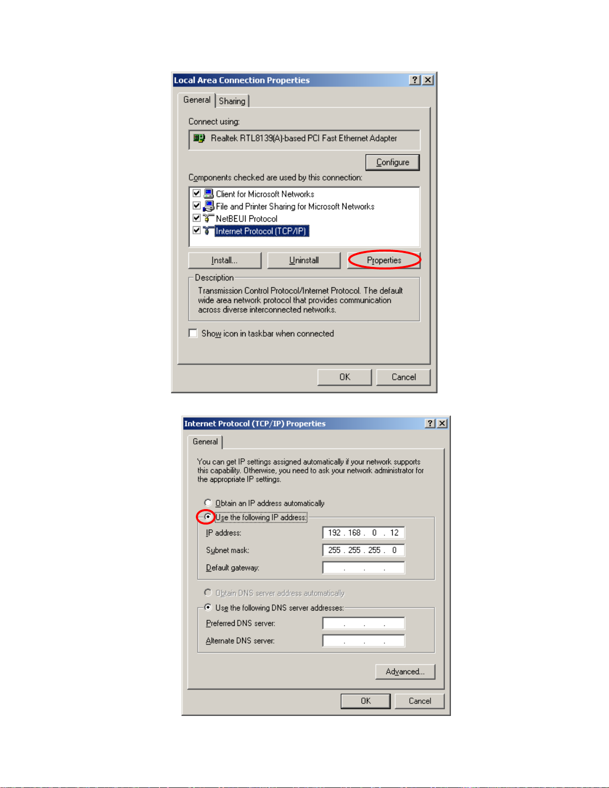
4. In the General tab, click the radio button of Use the following IP address. For example, in the
IP address field, enter in the following IP address: 192.168.0.12.
Page 10
Note: The default IP address of the Access Point is 192.168.0.10 so the IP address for the
Ethernet Adapter must follow the 192.168.0.x IP address format and the IP should not be the same
IP address assigned to any other devices in the network. (Do not use these reserved IP addresses:
192.168.0.1 and 192.168.0.10)
5. Under Subnet mask, input the following IP address: 255.255.255.0.
6. Click OK to save your settings and close the dialog box.
2.3 Configuring The Access Point – Basic
Settings
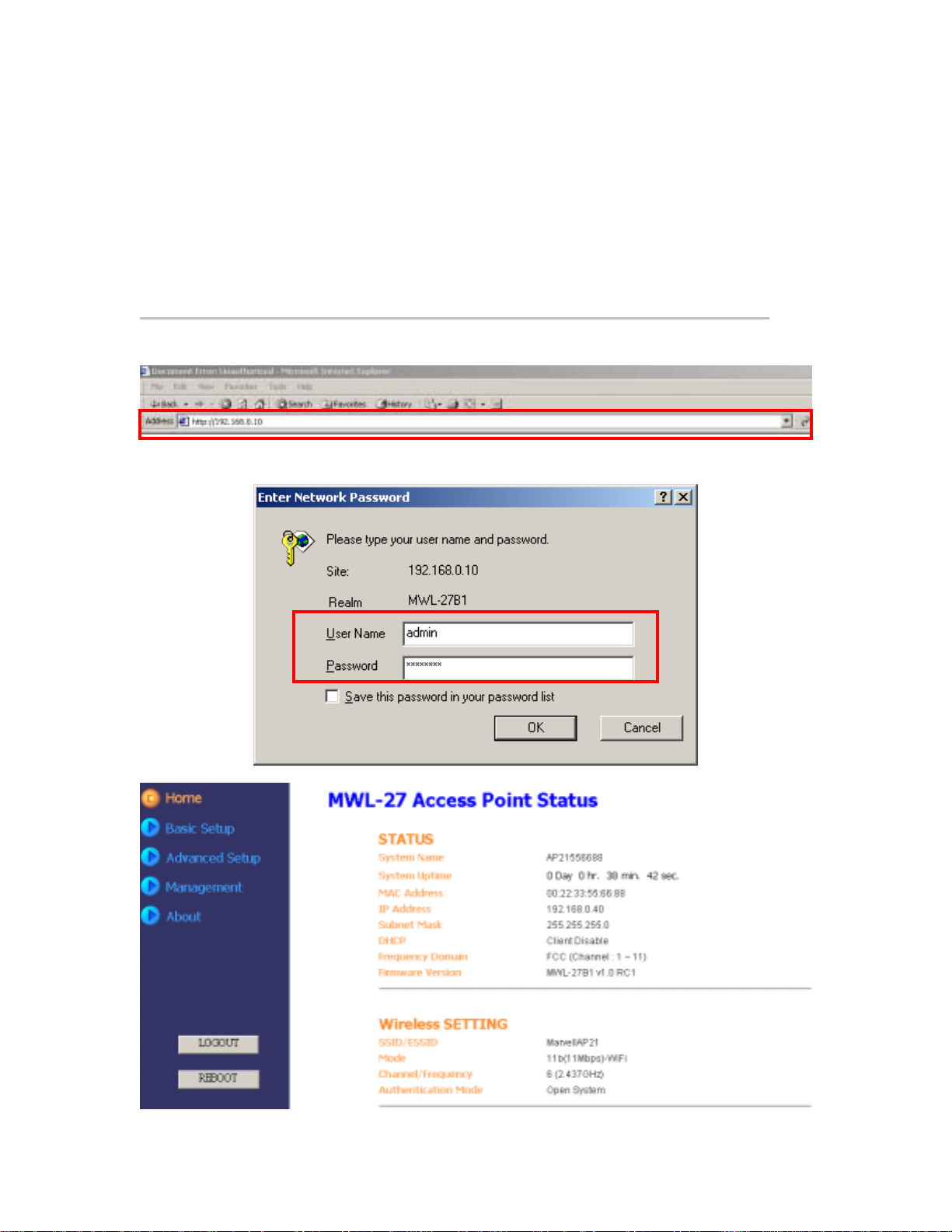
1. Open a web browser and enter http://192.168.0.10 in the Address field.
2. When the login screen shows up, type “admin” in the User Name field and “p assword” in the
Password filed. Please note that the user name and password are case sensitive.
3. Click OK and the configuration home page shows up.
Page 11
The homepage lists default settings and related info of the access point. You may click
menus listed on the left pane to start configure the AP. Click the LOGOOUT button on the left
pane will close the Configuration WEB page. Click REBOOT button to reboot the AP.
4. Basic Setup menu: The basic setup menu comprises three sub-menu: DHCP, Wireless and
Encryption.
In the DHCP item, if your network doesn’t provide DHCP function, you have to assign
an IP address for the AP.
In the Wireless item, you can change the SSID/ESSID. Please note that the SSID on
the wireless network adapters must be the same in order to communicate with the AP.
The Encryption item allows you to select one type of encryption to protect your data.
Please note that if the Encryption is enabled, then the encryption on the wireless
Ethernet adapters must be enabled and the WEP keys should be the same as the AP.
This utility supports both Hexadecimal and ASCII key formats. Click the drop-down
menu to choose one format. Only digits 0-9 and letters A-F are valid entries if you
select hexadecimal format.
Note: Please click Apply button to make your configuration tak e effect.
5. Advanced Setup Menu: If you want to modify advanced features, you can click the
Advanced Setup menu -> Advanced.
Page 12
6. Management Menu: The Management Menu comprises four items: System Name,
Password, Firmware and Profile items. You can rename the AP’s name, change the login
password, update firmware and create different profiles for future use.
Please refer to the following chapters for more details on using the Configuration Utility.
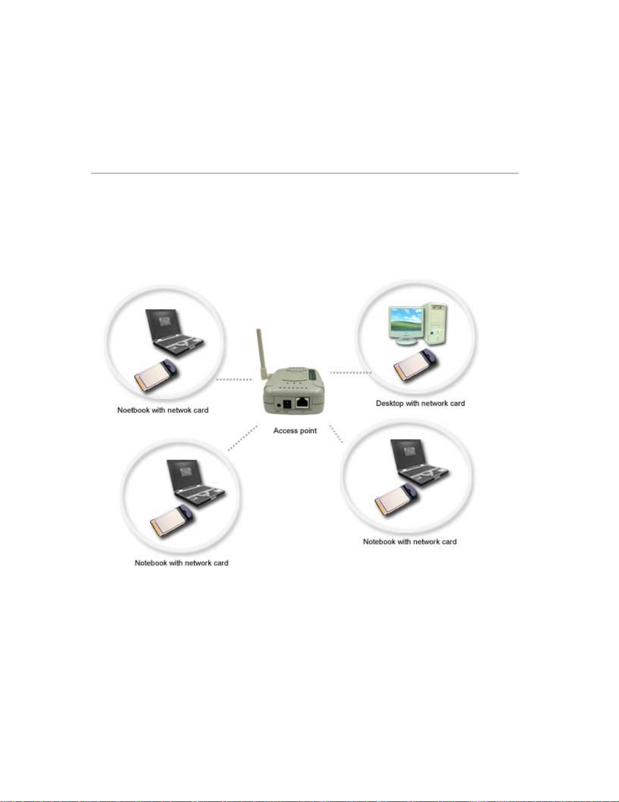
2.4 Application Scenario
Simple Wireless Access Point
In this application, the access point provides access for wireless stations to wired LANs and from
wired LANs to wireless stations. The wireless stations within the range of the access point may
communicate with each other via the access point. Please make sure that the IP address of the
computer with network cards should follow the same IP address format of the AP and the SSID
and the encryption keys should be the same as the AP.
Simple Wireless Access Point
Connecting The Access Point To A cable/DSL router, Ethernet switch or
hub
Steps:
1. Select a suitable site for the access point.
2. Connect an Ethernet cable between the access point and your cable/DSL router’s LAN port,
Ethernet switch, or hub by plugging one end of the cable into the RJ45 jack on the access
point and the other end into an open RJ45 jack on the cable/DSL router, Ethernet switch, or
hub.
Page 13

3. Connect the power supply to the access point by plugging the DC connector into the DC jack
on the WAP and plug the power supply into an electronic outlet. Verify that the Power LED and
LAN LED illuminate, this indicates that the access point is connected properly.
4. Install Ethernet cards into a laptop or desktop on your wireless network. Please refer to the
Installation Guide included with each product and make sure that the IP address of the
Ethernet cards are within the IP address range of your network. The SSID and encryption key
of the associated network cards should be the same as the AP.
5. You may refer to Chap ter 5: Troubleshooting to check the Ethernet adapter is correctly
installed.
Connecting the AP to a cable/DSL router, Ethernet switch or hub
Page 14

WB (Wireless Bridge) Mode – Ad-Hoc
Connect the access point to a s ingl e com put er a nd co nfigure the a cc ess poin t from AP mod e
to WB mode. All access points configured as WB mode should use the same radio channel.
Each single WB mode access point is wirelessly linked with another bridge. This mode
usually allows self-organizing connectivity and network services with no pre-exiting
infrastructure.
WB (Wireless Bridge Mode) – Ad-hoc
WB (Wireless Bridge) Mode – Infrastructure
The Wireless-Ethernet Bridge is one of an Access Point's client and bridges packets
wirelessly between two or more Ethernet LANs.
Page 15

WB (Wireless Bridge Mode) – Infrastructure
Page 16

Chapter3
Using the Configuration Utility
The Configuration Utility program for the access point is web-based. You will need a
web-browser such as the Internet Explorer 5.0 or higher, or the Netscape Navigator 6.0 or higher.
The computer that you are using for initial configuration must have an IP Address within
the same range as the IP Address o f the access point. Refer to Chapter 2 for assigning a static
IP address.
3.1 Open the Configuration Utility
1. Open a web browser and enter the default IP address 192.168.0.10 in the Address field.
2. When the login screen shows up, type “admin” in the User Name field and “p assword” in the
Password filed. Click OK. Please note that the user name and password are case sensitive.
3. The Configuration homepage shows up.
Page 17

3.2 Configuration Utility – Home Page
The Home page provides the current status of the Access Point so you can’t edit any item in this
page.
3.3 Basic Setup
Click Basic Setup menu from the left panel and you can see there are three items on the top of
this pane. See the below screen shot. The basic setup menu allows you to assign an IP address
for the access point, configure wireless settings and use WEP keys to encrypt data for a more
secure network communication.
Page 18

Basic Setup – DHCP Setting
Item Description
DHCP Client Enable
DHCP Client Disable
Note: Don’t forget to click Apply button to make configuration take effect. The AP will
restart automatically.
If your network provides the DHCP function and then you can click
the radio button to enable this function. The access point can
obtain an IP address and network configuration information from a
remote server.
If you want to manually assign an IP address, you must disable the
DHCP Client function and set a static IP address and subnet.
Basic Setup – Wireless Setting
The Wireless Setting allows you to configure the Access Point to communicate with other stations
on the wireless LAN.
Item Description
SSID/ESSID
Frequency Domain
Channel/Frequency
The SSID/ESSID can be regarded as a name for the wireless
network. Please note that the SSID on the wireless network
adapters must be the same in order to communicate with the
access point. If you want to change the SSID/ESSID, simply enter
a new SSID/ESSID in the SSID/ESSID field.
This field displays the type of regulatory regimen in use for this link.
It is fixed and can’t be changed.
There are 14 channels available for with the Access Point. There
may be restrictions on which channel can be used in some
countries. You can click the pull-down menu to change the
channel.
11 channels for United States
13 channels for Europe countries
Page 19

14 channels for Japan
Transmit Rate
Any Connection
Note: Don’t forget to click Apply button to make configuration take effect.
This field provides options for selecting data-transmitting rate of the
Access Point. There are five options – Auto, 1 Mbps, 2 Mbps, 5.5
Mbps and 11 Mbps. You can click the pull-down menu to select
one option. By default, the data rate is set to Auto allowing the
Access Point to adaptively set the Tx rate to the highest possible
rate for the WLAN condition. It’s recommended that you select the
Auto option.
To avoid broadcasting in the air so that every client with SSID
(ESSID) "ANY" will activate via the AP. This setting let you
configure if this AP is set for public purpose or under privacy.
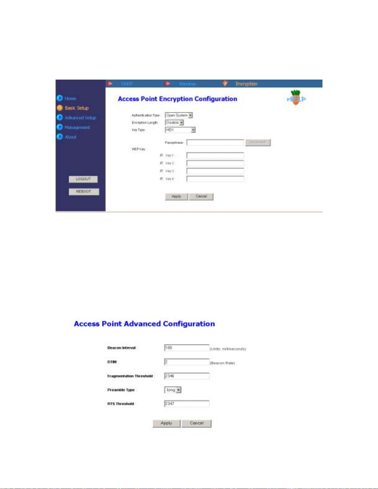
Basic Setup – Encryption Setting
The Encryption item provides WEP (Wired Equivalent Privacy) function to ensure a more secure
networking communication and prevent unauthorized access to your wireless network. The WEP
key for any wireless LAN adapter or access points associate with this access point should be the
same.
Item Description
Authentication Type
Encryption Length
There are three modes of authentication types. The default setting
is "Auto" and in this mode, the AP will automatically detect the
authentication type. "Open System" means that AP accepts the
mobile station at face value without verifying its identity. "Shared
key" requires a shared key be distributed to stations before
attempting authentication.
Click the drop-down menu to select 64 bits or 128 bits. The 128 bits
gives a higher level of security. The selection must be the same
between all connected network devices. You can see that as the
key length option is changed, the number of available characters in
the WEP Key Entry field is changed automatically. When using
Page 20

64-bits, you’ll need to enter a key having 10 hexadecimal
characters or 5 ASCII characters. While using 128-bits, you’ll have
to enter a key having 26 hexadecimal characters or 13 ASCII
characters.
Key Type
WEP Key
Note: Don’t forget to click Apply button to make configuration take effect.
This utility supports Hexadecimal, ASCII and Passphrase key
formats. Click the drop-down menu to choose one format. Only
digits 0-9, letters A-F and a-f are valid entries if you select
hexadecimal format. For ease-of-use, the utility can generate keys
using a "passphrase" that you enter. This passphrase can be easily
distributed to wireless-equipped computer users in your network.
For instance, creating a key using the passphrase "Passphrase"
generates four keys in 64-bit encryption mode and one key in
128-bit encryption mode. Users of laptops need only to enter the
passphrase and the key number into their computers’ wireless
management software to be able to communicate while using
encryption. All computers on the network must use the same
encryption rate and passphrase. The passphrase can be changed
as often as desired.
These four fields allow you to set four different 64-bit or 128-bit
alphanumeric keys for encryption. This item is a very convenient
and useful function when you want to match the WEP keys with
different vendor’s products. After you have set the WEP keys for
specific AP, instead of entering the WEP key every time, you just
click the radio button in front of the WEP key to enable the WEP
key of the associated device.
3.4 Advanced Setup
The Advanced Setup menu allows you to view associated WLAN cards, adding/blocking MAC
addresses to connect with this access point and configure advanced features the utility provides.
Advanced Setup – Station List
This page indicates the number of WLAN cards connect to the AP in the form of MAC address and
it will be refreshed every 20 seconds.
Page 21

Advanced Setup – Access Control
Manual Edit Area
The Access Control function allows you to add wireless LAN cards up to 64 entries in the form of
MAC address and allow/block these devices to communicate with the access point. The default
setting of Access Control is in “Disabled” mode, so you can select “Enable” from the drop-down
menu to activate this function. Click the Display Table/Hide Table to display or hide the Access
Control List.
Item Description
Access Control List
Edit Access Control List
The Access Control List indicates the allowed/blocked Ethernet
card status.
Quick Select MAC Address:
Click the pull-down menu of History Logs to select an associated
MAC address entry.
Manually Edit the MAC Address Here:
The MAC address entry you select from History Log will appear in
the Manual Edit field and allow you to configure its property. You
can click the pull-down menu from the Manual Edit area to select
Allow or Block the selected entry. Click Add and the entry will be
added into the Manual Edit table or click Remove to delete the
selected entry. If the Ethernet card you want to add doesn’t show
on the list, you can edit directly from Manual Edit area via typing its
MAC address.
Page 22

Advanced Setup – Block Log
g
This page indicates a log list up to 32 entries of MAC address of all wireless network devices once
blocked to the access point. Click Refresh to update this page.
Advanced Setup – Advanced
In this page, this utility gives you more flexibility to manage the access point. You can change
advanced configurations, such as Beacon Interval, DTIM, Fragmentation Threshold, Preamble
Type and RTS threshold.
Item Description
Beacon Interval
DTIM
Beacons are packets sent by an Access Point to synchronize a
wireless network. The value of beacon interval is depending on the
environment where the AP is operating. Specify a Beacon interval
value between 1 and 1000(units: ms). The default value is set to
100 milliseconds, i.e., ten beacons per second.
Enter a value between 1 and 255 for the Delivery Traffic Indication
Message (DTIM). A DTIM is a countdown informing clients of the
next window for listenin
to broadcast and multicast messages.
Page 23

When the Access Point has buffered broadcast or multicast
messages for associated clients, it sends the next DTIM with a
DTIM Interval value. AP clients hear the beacons and awaken to
receive the broadcast and multicast messages. The default value
for DTIM interval is set to 2.
Fragmentation
Threshold
Preamble Type
RTS Threshold
Note: Don’t forget to click Apply button to make configuration take effect.
This value should remain at its default setting of 2346. If you
experience a high packet error rate, you may slightly increase your
"Fragmentation" value within the value range of 256 to 2346.
Setting the Fragmentation value too low may result in poor
performance.
The Preamble Type defines the length of the CRC (Cyclic
Redundancy Check) block for communication between the Access
Point and roaming wireless adapters. Make sure to select the
appropriate preamble type and click the Apply button. Note: High
network traffic areas should use the shorter preamble type. The
default value for preamble length is set to long. The Short
Preamble option improves throughput performance. The default
setting is Long.
The RTS threshold is the packet size at which packet transmission
is governed by the RTS/CTS transaction. Each station can have a
different RTS threshold. If you encounter inconsistent data flow,
only minor modifications to the value range between 256 and 2347
are recommended. The default value for RTS Threshold is set to
2347.
3.5 Management Setup
The Management menu allows you to change the AP’s name, password, update firmware and
download profile you have created.
Management – System Name
The System name is used to help identify an access point when multiple APs are being used. For
instance, there maybe several APs in your network, you can identify different APs by giving them
different names. To enter a name, type a name in the System Name field and click Apply button to
make the configuration take effect.
Page 24

Management – Password
The Password page allows you to change the default username and password. Enter the new
username, password and click Apply button. For security, you should change the username and
password after you enter the web page. If you forgot the username and password, please go to the
Profile page and click Revert button to restore the setting into "factory" default or press the Reset
button on the back of the Access Point about 5 sec to restore the setting into "factory" default. The
username and password will be reset into the default value.
Management – Firmware
The firmware page allows you to update firmware. To update the firmware by web page, click the
Browse button first to select the file that had been saved in your laptop or PC (make sure to
change the file name into XXX.img). Then click the "Apply" button to update the firmware.
Click OK from the below dialog box and the firmware upgrade will start. It takes a few moments to
upgrade the firmware. Note: Do not power down or cancel the AP during the upgrade or the
upgrade will be terminated.
Page 25

Management – Profile
Creating a profile will save your time to re-configure network settings you have established. You
can save your current setting into a profile and download it to your laptop or PC. Also, you can
upload a profile you saved before. Please notice that the backup profile is "NOT" allowed to be
changed. In the bottom of this page, you can restore the setting into the factory setting if you click
Revert button.
Download: Allows you to save the current settings for future use. Click Download, and the
following dialog box will appear. Click OK to save the profile to your hard disk.
Page 26

From the following dialog box, specify a file path and click Save to save the profile.
After the profile has been downloaded completely, click Close to close the dialog box.
Page 27

Upload: Click Upload button to upload profile you have saved in your desktop or laptop. Click
Browse to specify the correct file path and click Upload to upload the profile.
Revert: Click Revert button and all the settings will restore to factory default settings. Click OK to
make sure that you want to retrieve the access point default setting.
Management – Select
Click Reboot button and the AP will be changed to Bridge mode.
3.6 About
You can have a basic concept of our company information through this page.
Page 28

Page 29

Chapter4
Bridge Mode Configuration
From AP mode, click the Management -> Select and click Reboot to switch to Bridge mode. It will
take a few seconds and the web browser will be refreshed. If not, you can manually open the web
browser.
4.1 Home menu
The Home page provides the system status, bridge setting, wireless setting and host table info.
You can view all the info but you can’t edit any item on this page.
Item Description
System Name
System Uptime
Firmware Version
Link Mode
IP Address
DHCP
Ethernet MAC Address
SSID/ESSID
Name of the Wireless-Ethernet Bridge.
It lists how long the AP has been turned on.
Indicates the current firmware version.
Indicates the current connection’s link mode.
The IP address of the Wireless-Ethernet Bridge.
Indicates the DHCP function is enabled or disabled.
Indicates the MAC address of the Bridge.
Name of the Wireless-Ethernet Bridge that users associate with
Page 30

Access Point.
Association
Wireless MAC Address
Host Table
Indicates that the Wireless-Ethernet Bridge is using 802.11b
transmit mode with Access Point.
The MAC address of the Wireless.
Indicates all hosts that behind the Wireless-Ethernet Bridge's LAN
port.
4.2 Wireless menu
The Wireless menu allows you to configure the SSID, Transmit/Receive mode, radio channel and
WEP settings.
Page 31

A
Item Description
SSID/ESSID
Transmit/Receive Mode
Channel/Frequency
Transmit Rate
Preamble
WEP Setting
WEP Key Length
Passphrase
WEP Key 1-4
uthenticated with Share
The SSID/ESSID can be regarded as a name for the wireless
bridge. If you want to change the SSID/ESSID, simply enter a new
SSID/ESSID in the SSID/ESSID field. The default value is ANY.
You can choose either Infrastructure or Ad-hoc mode.
Infrastructure: The Wireless-Ethernet Bridge is one of an Access
Point's client. The host links with the Wireless-Ethernet Bridge's
LAN port will transmit/receive data to other host via the bridge to
the Access Point.
Ad-hoc: The Wireless-Ethernet Bridge is linked with another
Bridge. This mode usually allows self-organizing connectivity and
network services with no pre-exiting infrastructure.
There are 14 channels available for with the Access Point. There
may be restrictions on which channel can be used in some
countries. You can click the down-arrow button to select a channel.
11 channels for United States
13 channels for Europe countries
14 channels for Japan
This function is only available in Ad-hoc mode and each
Wireless-Ethernet bridge should be set to the same channel;
otherwise, the connection won’t be built.
This field provides options for selecting data-transmitting rate of the
Access Point. There are five options – Auto, 1 Mbps, 2 Mbps, 5.5
Mbps and 11 Mbps. You can click the down-arrow button to select
one option. By default, the data rate is set to Auto allowing the
Access Point to adaptively set the Tx rate to the highest possible
rate for the WLAN condition. It’s recommended that you select the
Auto option.
The Preamble Type defines the length of the CRC (Cyclic
Redundancy Check) block for communication between the
Wireless-Ethernet Bridge and roaming wireless adapters. Make
sure to select the appropriate preamble type and click the Apply
button.
Note: High network traffic areas should use the shorter preamble
type. CRC is a common technique for detecting data transmission
errors. The default value for preamble length is set to long.
You have to click the down-arrow button to select Enable and the
WEP settings will be available.
Click the radio button of 64 bits or 128 bits. The 128 bits gives a
higher level of security. The selection must be the same between
all connected network devices. You can see that as the key length
option is changed, the number of available characters in the WEP
Key Entry field is changed automatically. When using 64-bits, you’ll
need to enter a key having 10 hexadecimal characters or 5 ASCII
characters. While using 128-bits, you’ll have to enter a key having
26 hexadecimal characters or 13 ASCII characters.
To use the passphrase mode, you need to input a random number
or any key you want. Then press the "Generate!!!" button, the
passphrase will generate four sets of key automatically.
These four fields allow you to set four different 64-bit or 128-bit
alphanumeric keys for encryption. This item is a very convenient
and useful function when you want to match the WEP keys with
different vendor’s products.
Click the down-arrow button to select Disable or Enable. If you
Page 32

Key mode
Apply, Cancel Button
select Enable, then it requires a shared key be distributed to
stations before attempting authentication.
Apply: Make your settings take effect. There will be a pop-up
message shows up, please follow the on-screen description to
reboot your AP.
Cancel: Abort all configurations.
4.3 Bridge menu
In the Bridge page, you can type a Wireless-Ethernet bridge name, enable/disable DHCP setting
and enable/disable MAC cloning.
Item Description
Bridge Name
DHCP Setting
IP Address Setting
MAC Cloning Mode
Enter a new bridge name in this field.
If your network provides DHCP function, and then you can click the
radio button of Enable to enable this function.
If your network doesn’t provide DHCP function, you have to assign
an IP address for the AP. Type the IP address in the IP filed. Also,
type the subnet mask and default gateway in the relative fields.
This function will clone the MAC address of the host as wireless
bridge’s own MAC. This can be enabled when there is ONLY one
single host. Running NetBEUI/IPX protocol requires MAC Cloning
Enable.
4.4 Site Survey menu
The Site Survey page provides information of any access point near this Wireless-Ethernet
Page 33

Bridge. You can find the numbers of access point, the MAC address of the access point, the
channel it uses and if the WEP setting is enabled or not. Click Scan button to refresh the table.
4.5 Advance menu
The Advance menu allows you to revert the AP to default setting, upgrade firmware and change
password.
Page 34

p
p
g
Revert to Factory Default Setting
Click the RESTORE button and all settings will be reverted to default setting.
Firmware Upgrade Setting
To update the firmware via web page, click the Browse button first to select the file that had
been saved in your laptop or PC (make sure to change the file name into xxx.img). Then click
the "Apply" button to update the firmware.
Click OK from the confirm dialog box and the firmware upgrade will start. It takes a few
moments to upgrade the firmware. If the firmware upgrade is completed, there will be a
message indicating you the process is successful. Please follow on-screen description to
reboot the AP and open the WEB browser again.
Note: Do not
Password Setting
You can assign a new password for the AP. Type the new password in the Password field.
You can close the browser and type the new password to test if your password takes effect.
ower down or cancel the AP during the u
rade or the upgrade will be terminated.
4.6 Select menu
The Select page allows you to change from Wireless Bridge mode to Access Point mode.
Click the Reboot button and the access point will be changed to AP mode. It will take a few
seconds to update the web page. If the web page is not updated, you can manually open the web
browser.
Page 35

Page 36

Troubleshooting
1. Revert the access point to Factory Default settings
You may follow the following steps to hard-reset the access point.
Reset Button
Locate the Reset button on the back of the access point.
Chapter5
Use a thin metal object, such as a paper clip or a pen point to press and hold the Reset
button for about 5 seconds and then release.
After the access point reboots (this may take a few moments) it will be reset to the
factory Default settings.
2. The computer used to configure the access point cannot access the Web Configuration
Page.
Check that the LAN LED on the access point is ON. If the LED is not ON, check that
the cable for the Ethernet connection is securely inserted and the power cable is
plugged into the power jack securely.
Check that the Ethernet card is working properly. Please check that the driver for the
network card is installed properly and check that the drivers are loaded properly.
Pleaser refer to the below point 3.
Check that the IP Address of the Ethernet card is in the same range and subnet as the
access point. Please refer to section 2 of Chapter 2: Configuring the Ethernet Adapter.
Verify that if you correctly type the Username and Password.
Note: The default IP address of the Access Point is 192.168.0.10 so the IP address for the
Ethernet Adapter must follow the 192.168.0.x IP address format and the IP should not be the
same IP address assigned to any other devices in the network. (Do not use these reserved
IP addresses: 192.168.0.1 and 19 2.168.0.10.)
Do a Ping test to make sure that the access point is responding. In the example, from
Windows Start menu -> Run>Type Command>Type ping 192.168.0.20. A successful
Page 37

ping will show four replies.
3. Verify that the driver for the Ethernet card has installed successful
If you want to check that the driver’s installation is successful or not, follow the next steps. Your
Ethernet card model may differ from this example but the verification procedure is the same.
Right-click mouse button on the My Computer icon on your Windows desktop, and
highlight Properties from the pop-up menu.
The System Properties screen will be pop-up. Under Hardware tab, click Device
Manager….
Page 38

After clicking Device Manager…, the following screen will be shown. Click on the +
symbol in front of “Network adapters” and see if an item labeled Wireless 802.11b
CardBus Adapter (34B1) is visible. If you don’t see the item below the network
adapter icon but a”?” or “!” symbol is displayed, it means that the driver installation was
unsuccessful. Highlight “Wireless 802.11b CardBus Adapter (34B1)”, right-click
mouse button and select “Properties”.
Page 39

Click the General tab, if the Device Status field reports that “This device is working
properly”, it means that the driver has been installed successfully.
Page 40

4. The computers with the wireless Ethernet cards installed can’t connect to the network
through the access point.
Make sure that each wireless client is configured to connect to the SSID of the AP. The
default SSID of the AP is MWL-27.
Make sure that each wireless client is configured to the same encryption setting with
the AP.
 Loading...