

Page 1
E18-MS1PA1-PCB_Datasheet
No
.
Parameter item
Parameter
details
Description
1
RF IC
CC2530
TI
2
Size
16 * 27mm
- 3 Weight
1.6g
Average weight
4
Frequency
2405 ~ 2480MHz
2.4GHz IEEE 802.15.4
5
PCB
4-layers
Impedance-matching, lead-free
6
Connector
3 * 8 * 1.27mm
SMD
7
Supply Voltage
2.0 ~ 3.6V DC
Notes: the voltage higher than 3.6V is
forbidden
8
Communication level
0.7VCC ~ 5V
VCC refers to the supply voltage
9
Operation Range
800m
Clear and open area, 4dBm,height: 2m,
Air date rate: 250kbps
10
Power
20dBm
100mW
11
Air data rate
250kbps
12
Sleep current
1.2uA
MCU in sleep,wireless closed,VCC=3.3V
13
Transmitting current
140mA@20dBm/
28mA@4dBm
Power supply must be greater than
300mA/60mA
14
Receiving current
42mA/27mA
Receives an average current
15
Communication
interface
I/O
See details in Pin definition
16
Transmitting length
1~103 bytes
For one package
17
Receiving length
1~103 bytes
For one package
18
RSSI support
Available
Find more details on
<CC2530 Datasheet>
19
Antenna type
PCB
50Ω characteristic impedance
20
Operating temperature
-40 ~ +85℃
-
21
Operating humidity
10% ~ 90%
No condensation
22
Storage temperature
-40 ~ +125℃
-
23
Sensitivity
-97dBm@250kbp
s
Find more details on
<CC2530 Datasheet>
1. Introduction
18 is based on originally imported RF chip CC2530 form TI in America. The IC chip is integrated with 8051
microcontroller and wireless transceiver inside, which is applicable to Zigbee design and 2.4GHz IEEE 802.15.4
protocol. All the IO ports are led out by the module, which means that multi-aspect development is realizable.
2. Electrical parameter
Page 2
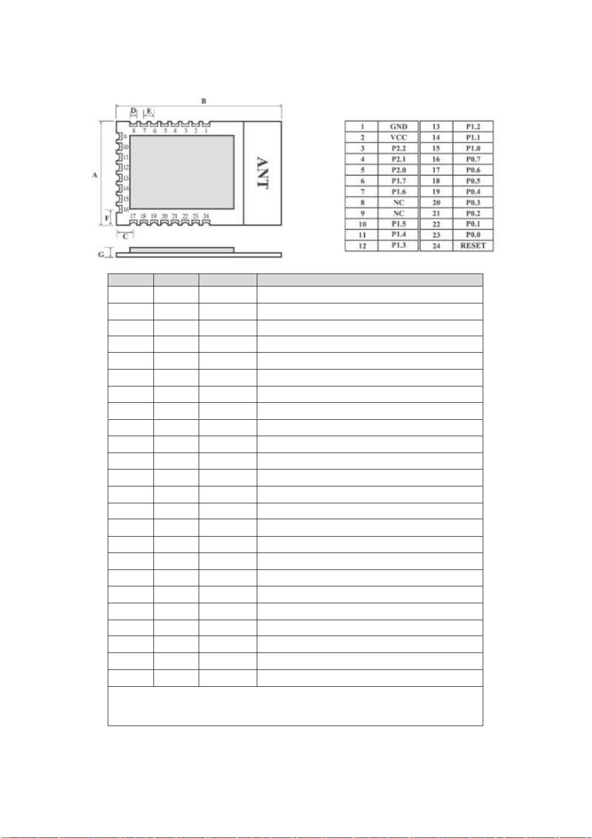
3. Pin definition
Pin No.
Pin item
Pin direction
Pin application
1
GND
Ground
2
VCC
Power supply 2.0V ~ 3.6V DC
3
P2.2
Input/output
MCU GPIO
4
P2.1
Input/output
MCU GPIO
5
P2.0
Input/output
MCU GPIO
6
P1.7
Input/output
MCU GPIO
7
P1.6
Input/output
MCU GPIO
8
NC
Empty 9 NC
Empty
10
P1.5
Input/output
MCU GPIO
11
P1.4
Input/output
MCU GPIO
12
P1.3
Input/output
MCU GPIO
13
P1.2
Input/output
MCU GPIO
14
P1.1
Input/output
MCU GPIO/PA transmitting control the pin
15
P1.0
Input/output
MCU GPIO/PA receiving control the pin
16
P0.7
Input/output
MCU GPIO/PA receiving the high gain control the pin
17
P0.6
Input/output
MCU GPIO
18
P0.5
Input/output
MCU GPIO
19
P0.4
Input/output
MCU GPIO
20
P0.3
Input/output
MCU GPIO
21
P0.2
Input/output
MCU GPIO
22
P0.1
Input/output
MCU GPIO
23
P0.0
Input/output
MCU GPIO
24
RESET
Input
Reset
★ Please see more details in < CC2530 Datasheet >, ★
★ such as pin definition, software drivers, and communication protocol. ★
Page 3

4. Notes
No.
Item
Attention
1
Static electricity
Please try not to touch the electronic components with bare hands.
2
Welding
When welding, soldering iron needs grounding. The producer needs to
wear cable electrostatic bracelet which is grounding when mass
production.
3
Power supply
Power quality has a great impact on the performance of the module,
please make sure the power supply has small ripple and avoid the
frequent and large jitter. π filter is recommended(Ceramic capacitor / /
tantalum capacitor + inductance).
4
Ground
Single-point grounding is recommended.
0 ohm resistor or 10mH inductance are recommended.
5
Antenna
How to install antenna has a great impact on the performance of the
module, please make sure the antenna is exposed and vertical upward. It
will lead to the transmitting distance greatly weakened if the antenna
installs in the interior of housing.
FCC Statement
This device complies with part 15 of the FCC Rules. Operation is subject to the following two
conditions: (1) This device may not cause harmful interference, and (2) this device must accept any
interference received, including interference that may cause undesired operation.
Any Changes or modifications not expressly approved by the party responsible for compliance could
void the user's authority to operate the equipment.
The modular can be installed or integrated in mobile or fix devices only. This modular cannot be
installed in any portable device .
FCC Radiation Exposure Statement
This modular complies with FCC RF radiation exposure limits set forth for an uncontrolled environment.
This transmitter must not be co-located or operating in conjunction with any other antenna or
transmitter. This modular must be installed and operated with a minimum distance of 20 cm between
the radiator and user body.
If the FCC identification number is not visible when the module is installed inside another device, then
the outside of the device into which the module is installed must also display a label referring to the
enclosed module. This exterior label can use wording such as the following: “Contains Transmitter
Module FCC ID: 2ALPH-E18 Or Contains FCC ID: 2ALPH-E18”
When the module is installed inside another device, the user manual of the host must contain below
warning statements;
1. This device complies with Part 15 of the FCC Rules. Operation is subject to the following two
conditions:
(1) This device may not cause harmful interference.
(2) This device must accept any interference received, including interference that may cause undesired
operation.
2. Changes or modifications not expressly approved by the party responsible for compliance could void
the user's authority to operate the equipment.
The devices must be installed and used in strict accordance with the manufacturer's instructions as
described in the user documentation that comes with the product.
 Loading...