

Page 1
E01-ML01DP5 Datasheet V1.0 Website: www.cdebyte.com/en
No.
Parameter item
Parameter details
Description
1
RF IC
nRF24L01P
Nordic 2 Size
18 * 33.4 mm
-
3
Weight
4.9g
Average weight 4 PCB
SMT
Lead-free
5
Connector
2 * 4 * 2.54 mm
Plug-in
6
Supply voltage
2.0 ~ 3.6V DC
Notes: the voltage higher than 3.6V is forbidden
7
Frequency
2400 ~ 2525MHz
Adjustable
8
Communication level
0.7VCC ~ 3.6V
VCC refers to the supply voltage
9
Operation Range
2000m
10
Transmitting Power
Maximum 20dBm
100mW
11
Air data rate
250kbps~2Mbps
250kbps, 1Mbps, 2Mbps
12
Sleep current
1.0uA
nRF24L01P sets as power-down, CE low level
13
Transmitting current
130mA@20dBm
≥300mA
14
Receiving current
21mA
CE=1
15
Communication interface
SPI
Data rate: up to 10Mbps
16
Transmitting length
3 level FIFO.
32 bytes (maximum) for one package
17
Receiving length
3 level FIFO.
32 bytes (maximum) for one package
18
Antenna type
SMA-K
50 ohm characteristic impedance
19
Sensitivity
-106dBm@250kbps
Please see more in IC datasheet
20
Operating temperature
-40 ~ +85℃
-
21
Operating humidity
10% ~ 90%
Relative humidity, no condensation
22
Storage temperature
-40 ~ +125℃
-
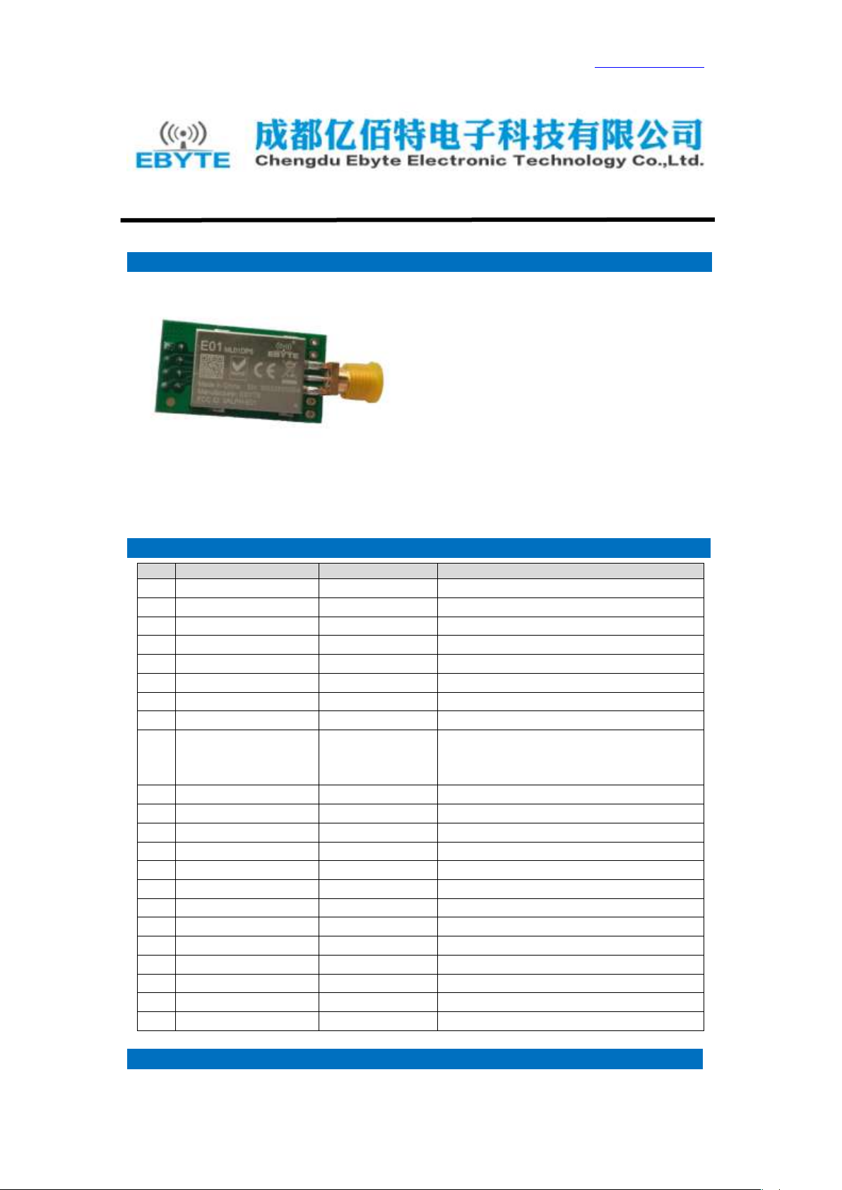
--1. Introduction E01
E01 is the iconic product of EBYTE. This
nRF24L01+PA+LNA RF module operates at 2.4 GHz, with
SPI interface and stable production, which make the
module suitable for various applications.
E01 is based on original imported nRF24L01P form
Nordic in Norway. And equipped with 20dBm power
amplifier chip imported from USA, which makes the
transmitting power achieves 100mW (20dBm) while the
receiving sensitivity enhanced by 10dB. Those features
make the transmitting distance 10 times longer than nRF24L01P itself. The anti-interference shielding cover on the
module makes the anti-interference performance better.
--2. Electrical parameter E01
Test condition: Clear and open area, 20dBm,
antenna gain: 2dBi,height: 2m,Air date rate:
250Kbps
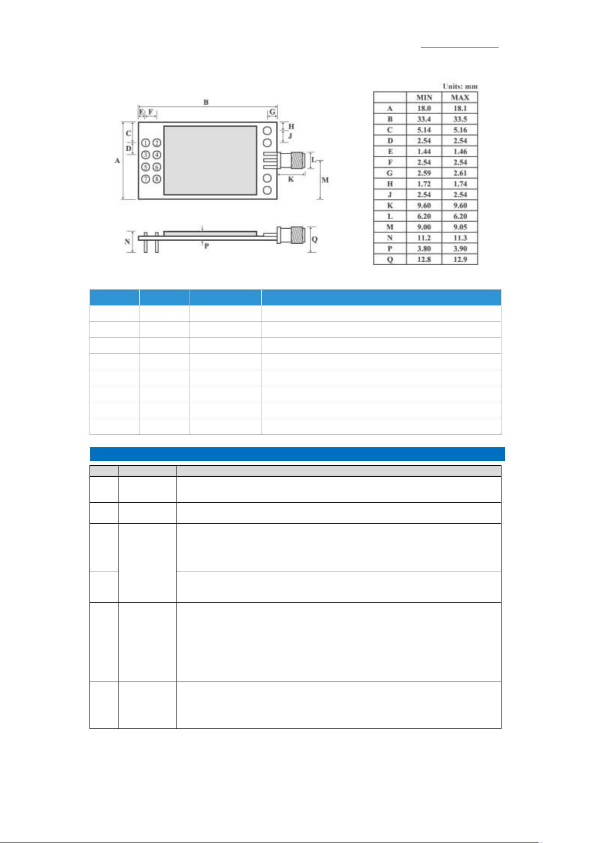
--3. Pin definition E01
Page 4 of 4 Technical support: support@cdebyte.com
Page 2
E01-ML01DP5 Datasheet V1.0 Website: www.cdebyte.com/en
Pin No.
Pin item
Pin direction
Pin application
1
GND
Ground 2 VCC
Power supply 2.0V ~ 3.6V DC
3
CE
Input
Chip Enable
4
CSN
Input
SPI Chip select
5
SCK
Input
SPI clock
6
MOSI
Input
SPI master output slave input
7
MISO
Output
SPI master input slave output
8
IRQ
Output
Interrupt request.
No.
Item
Attention
1
Static
electricity
Please try not to touch the electronic components with bare hands.
2
Welding
When welding, soldering iron needs grounding. The producer needs to wear cable
electrostatic bracelet which is grounding when mass production.
3
Power
supply
Power quality has a great impact on the performance of the module, please make sure
the power supply has small ripple and avoid the frequent and large jitter. π filter is
recommended(Ceramic capacitor / / tantalum capacitor + inductance).
4
Ground
Single-point grounding is recommended. 0 ohm resistor or 10mH inductance are
recommended.
5
Antenna
How to install antenna has a great impact on the performance of the module, please
make sure the antenna is exposed and vertical upward. It will lead to the transmitting
distance greatly weakened if the antenna installs in the interior of housing. When the
module is installed in the interior of the housing, high-quality antenna extension line
can be used to extend the antenna to the outside of the housing.
6
Interference
If there are different modules work in other frequency band in the same product, the
user need to plan rationally and take measures to shield, in case the harmonic
interference and intermodulation interference exist.
--4. Note E01
Page 4 of 4 Technical support: support@cdebyte.com
Page 3

E01-ML01DP5 Datasheet V1.0 Website: www.cdebyte.com/en
FCC Statement
This device complies with part 15 of the FCC Rules. Operation is subject to the following two
conditions: (1) This device may not cause harmful interference, and (2) this device must
accept any interference received, including interference that may cause undesired operation.
Any Changes or modifications not expressly approved by the party responsible for
compliance could void the user's authority to operate the equipment.
FCC Radiation Exposure Statement
This modular complies with FCC RF radiation exposure limits set forth for an
uncontrolled environment. This transmitter must not be co-located or operating in conjunction
with any other antenna or transmitter.
If the FCC identification number is not visible when the module is installed inside another
device, then the outside of the device into which the module is installed must also display a
label referring to the enclosed module. This exterior label can use wording such as the
following: “Contains Transmitter Module FCC ID: 2ALPH-E01 Or Contains FCC ID:
2ALPH-E01”
When the module is installed inside another device, the user manual of the host must
contain below warning statements;
1. This device complies with Part 15 of the FCC Rules. Operation is subject to the following two
conditions:
(1) This device may not cause harmful interference.
(2) This device must accept any interference received, including interference that may
cause undesired operation.
2. Changes or modifications not expressly approved by the party responsible for compliance could
void the user's authority to operate the equipment.
The devices must be installed and used in strict accordance with the manufacturer's instructions
as described in the user documentation that comes with the product.
Page 4 of 4 Technical support: support@cdebyte.com
 Loading...